Dynamic nonlinear inverse-model based control of a twin rotor system using
adaptive neuro-fuzzy inference system
S. F. Toha and M. O. Tokhi
Dept. of Automatic Control and Systems Engineering University of Sheffield
United Kingdom [email protected]
Abstract— A dynamic control system design has been a great demand in the control engineering community, with many applications particularly in the field of flight control. This paper presents investigations into the development of a dynamic nonlinear inverse-model based control of a twin rotor multi-input multi-output system (TRMS). The TRMS is an aerodynamic test rig representing the control challenges of modern air vehicle. A model inversion control with the developed adaptive model is applied to the system. An adaptive neuro-fuzzy inference system (ANFIS) is augmented with the control system to improve the control response. To demonstrate the applicability of the methods, a simulated hovering motion of the TRMS, derived from experimental data is considered in order to evaluate the tracking properties and robustness capacities of the inverse- model control technique.
Keywords-Inverse-model, twin rotor multi-input multi-output system (TRMS), adaptive neuro fuzzy system (ANFIS).
I. INTRODUCTION
The development of mathematical models of a system has been predominant in conventional control system design, which attempt to describe the dynamic behaviour of the system. Due to the continuous development of automation systems and more demanding control performance requirements, conventional control methods are not always adequate. On the other hand, practical control problems are usually nonlinear, imprecise and the basic physical processes in it are not completely known a priory. These types of model uncertainties are extremely difficult to manage, even with conventional adaptive techniques. The need for control methods for the aforementioned processes becomes very important. Therefore, this paper addresses an inverse model-based control of a twin rotor multi-input multi-output system (TRMS) using intelligent system techniques for input tracking in hovering position. Station keeping (i.e. hovering) is vital for a variety of flight missions such as load delivery, air-sea rescue etc. Yet maintaining a station is one of the most difficult problems in helicopter flight because in this mode the dynamically unstable helicopter is flying at near zero forward speed.
Inverse dynamics identification is defined as finding the inverse mapping of a system. It is useful to know the inverse dynamics of a plant in order to control it. The aim of dynamic model inversion is to cancel the flexural effects of the controlled plant by constructing its inverse mapping and
using it in the control law. This makes it feasible to employ linear control system tools for achieving the desired control objectives [1]. The concept of inverse-model based control has been used to solve problems of common engineering applications. Danai [2], uses feedforward network as the inverse model of the effect of the blade adjustment on helicopter vibrations. This method includes priory knowledge of the process by defining the initial coefficients of the internal model. Shuo and Jihong [3] on the other hand designed a dynamic inversion controller for both altitude loop and attitude loop from a simplified mathematical model derived from generic YAMAHA R-50 unmanned helicopter simulation model. Nonlinear inverse model has also been designed by Cao et al. [4] in the flight control during windshear. A low-altitude windshear penetration flight control law is designed providing improved level of performance in the trajectory control of the aircraft. Model based inversion control was further used by Haïat et al. [5] to detect and locate accurately any defect locations on a steel component using ultrasonic waves. Moreover, Rahideh et al. [6] have developed a model inversion control in combination with genetic algorithm to tune a proportional-derivative (PD) controller. A neural network element is then integrated with the feedback control system to compensate for model inversion error. However, a major problem with this kind of approach is, it needs a priori knowledge as well as the mathematical model of the system. Therefore, this work is done using a non-parametric approach utilizing the input and output data of the system in order to develop the inverse model of a TRMS.
The nonlinear forward model of the TRMS has been successfully obtained and reported in [7], [8], [9]. Therefore, the same system identification technique based on experimental input-output data pairs is employed to obtain the inverse model of the system. The advantage of an inverse model is that it can be used to build a controller. The desired behavior is treated as an input variable in the model, and the action is treated as an output variable. Since the input–output dynamics of the model and the controller are the same, they share the same stability properties, thus it is sufficient to show stability of the model only, when determining stability of the model and of the controller [10]. An adaptive neuro-fuzzy inference system (ANFIS) is augmented to the control system to improve the control response. Thus, the control techniques embraced in this work are augmented ANFIS 2009 Third UKSim European Symposium on Computer Modeling and Simulation
Unrecognized Copyright Information DOI 10.1109/EMS.2009.106
107
2009 Third UKSim European Symposium on Computer Modeling and Simulation
978-0-7695-3886-0/09 $26.00 © 2009 IEEE DOI 10.1109/EMS.2009.106
107
2009 Third UKSim European Symposium on Computer Modeling and Simulation
978-0-7695-3886-0/09 $26.00 © 2009 IEEE DOI 10.1109/EMS.2009.106
with feedforward inverse-model control and augmented ANFIS and feedback inverse-model control.
II. EXPERIMENTALSET-UP
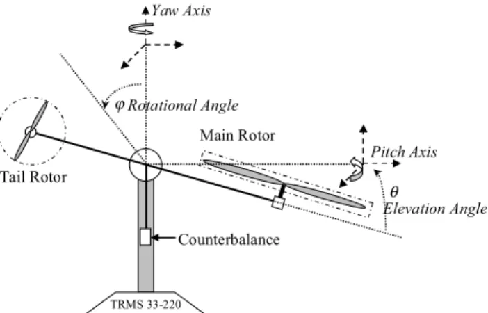
The twin-rotor multiple-input multiple-output (MIMO) system (TRMS) is a laboratory set-up developed by Feedback Instruments Limited [11] for control experiments. Its behaviour in certain aspects resembles that of a helicopter. For example, it possesses a strong cross-coupling between the collective (main rotor) and the tail rotor, like a helicopter. A schematic diagram of the TRMS used in this work is shown in Figure 1. It is driven by two DC motors. Its two propellers are perpendicular to each other and joined by a beam pivoted on its base that can rotate freely in the horizontal and vertical planes. The beam can thus be moved by changing the input voltage in order to control the rotational speed of the propellers. The system is equipped with a pendulum counterweight hanging from the beam, which is used for balancing the angular momentum in steady-state or with load.
Tail Rotor Main Rotor TRMS 33-220 Counterbalance ϕRotational Angle Pitch Axis Yaw Axis θ Elevation Angle
Figure 1. Twin rotor multi input multi output system
The system is balanced in such a way that when the motors are switched off, the main rotor end of the beam is lowered. The controls of the system are the supply voltages of the motors. A change in the voltage value results in a change of the rotational speed of the propeller, which in turn results in a change of the corresponding position of the beam. It is important to note that the geometrical shapes of the propellers are not symmetric. Accordingly, the system behaviour in one direction is different from that in the other direction. Rotation of a propeller produces an angular momentum which, according to the law of conservation of angular momentum, is compensated by the remaining body of the TRMS beam. This results in interaction between the moment of inertia of the motors with propellers. This interaction directly influences the velocities of the beam in both planes. The measured signals are: position of the beam, which constitutes two position angles, and the angular velocities of the rotors. Angular velocities of the beam are software reconstructed by differentiating and filtering the measured position angles of the beam.
III. ADAPTIVE NEURO-FUZZY INFERENCE SYSTEM (ANFIS)
In this work, a Takagi-Sugeno-Kang type fuzzy model is used. This comprises two main components, the antecedent and consequent parts. For simplicity, the ANFIS structure is set to have 2 inputsx1andx2as shown in Figure 2 [12].
This fuzzy model has rules in the following form: Ri:Ifx1isAi1Andx2isAi2Thenyiisfi(x) (1) wherex1andx2are the input variables to the ANFIS.Ai1,…,
Ainare the linguistic terms of input membership function for theith rule (i = 1, 2, …, n) and yi is the consequent part which is the mathematical function of ith rule. Fuzzy setAij at layer 1 uses a Gaussian membership function for each input variable and it has the form
⎪⎭ ⎪ ⎬ ⎫ ⎪⎩ ⎪ ⎨ ⎧ ⎟ ⎟ ⎠ ⎞ ⎜ ⎜ ⎝ ⎛ − − = 2 exp ) ( ij ij j ij m x x A σ (2)
where mijandσijrepresent the centre and width of the fuzzy set Aij respectively. Parameters in this layer are referred to
asantecedent parameters. The output of a fuzzy inference
system withnrules is obtained by weighting the real values of consequent parts of all rules with the corresponding membership grade
∑
∑
= = = = n i n i i i i i w w f w y 1 1 ˆ (3) where∏
= = n j i ij i A x w 1 )( where inputs arex1andx2 (4) and ) ( ) ( i 1 i 2 i i i f x ax bx c y = = + + (5)
where
{
ai,bi,ci}
is the parameter set and it is referred to asconsequent parameters.
In this work, the ANFIS architecture uses particle swarm optimization (PSO) to determine the antecedent parameters and recursive least square (RLS) algorithm to determine the consequent parameters. The nonlinear forward modeling of the TRMS using this approach has been proposed in previous work by the authors [9]. This method is referred to as hybrid learning. A step in the learning procedure has two passes: in the first or forward pass, the input patterns are propagated, and the optimal consequent parameters are estimated by RLS procedure, while the antecedent parameters are assumed to be fixed for the current cycle through the training set. In the second or backward pass the patterns are propagated again, and in this epoch, PSO is used to modify the antecedent parameters, while the consequent parameters remain fixed. This procedure is then iterated until the error criterion is satisfied.
IV. NONLINEAR INVERSEMODELIDENTIFICATION In this section, the identification of the inverse model of a TRMS is discussed. The forward non-parametric model of the system that mimics well the TRMS behaviour has been obtained in the previous work using the same ANFIS approach [7],[9]. The model is obtained using an experimental input-output data pairs is proved to replicate well the behaviour of the system. It has also been validated using both time domain tracking and frequency domain response. Dynamic model inversion is a popular method to achieve feedback linearization because it is easy to apply and its physical meaning is clear [13]. The inverse model is designed to accurately replicate the inverse system behaviour. The input of the inverted model is pitch angle of rotor and the output is the main voltage to the system. Figure 3 depicts the schematic diagram of the inverse model identification technique. TRMS Plant ANFIS Inverse Model Learning algorithm ) (t u y(t) ) (t ε
∑
) ( ˆ t u+
_
Figure 3. Schematic diagram of the inverse model identification In the inverse modeling structure, data are presented to the ANFIS network using the NARMA model structure [14]. The model is described as
)] ( ),..., 2 ( ), 1 ( ), ( ),..., 2 ( ), 1 ( [( ) ( ˆ n t u t u t u n t y t y t y f t u − − − − − − = (6)
whereuˆ(t)is the output vector determined by the past values of the system input vector and output vector. Thef(•)is the system mapping constructed by the ANFIS algorithm. As
) (•
f here is a non-linear function, (6) represents a NARMA model as shown in Figure 3. It is noted that the output of the inverse model is a function of the plant input and output. This implies that the output consists of the one-time-step ahead predictions as they are one step ahead where it is a prediction error method. The dynamic inverse model based controller is realized using the MATLAB/Simulink environment.
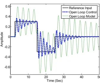
The obtained inverse model of the system is then set in cascade with the non-parametric forward model of TRMS as shown in Figure 4. The simplest approach for controller design is a completely opem-loop control strategy, in which the controller is the inverse of the process. For this open-loop inverse model control, the input to the inverted model is the desired value of pitch angle, αref(t) , the output of the inverted model, that is the input to the plant, is the voltage of the main rotor,u(t), and the output of the plant is the pitch angle,α(t) . The output response of the open-loop control in Figure 5 shows that the inverse model has reduced system vibration to some extent, around the set point (rigid-body motion). The output response of the open loop inverse model is compared with the output response of the uncontrolled TRMS plant. Therefore, it is evident that the inverse model technique can be used to enhance the tracking characteristics of the system. Inverse Model TRMS Model ) (t ref α u(t) α(t)
Figure 4. The open loop inverse model control
0 10 20 30 40 50 -0.6 -0.4 -0.2 0 0.2 0.4 0.6 Time (Sec) A m pl it ude Reference Input Open Loop Control Open Loop Model
Figure 5. The open loop response of model and inverse control
109 109
V. INVERSE-MODELBASEDCONTROLAPPROACHES
A. Direct inverse model
After the promising results from the open-loop inverse control, direct inverse control is developed to further investigate the inverse model in closed-loop (Figure 6). The TRMS inverse model will have some inaccuracies which may lead to deviations between the reference input and the system output. However, it has been noticed that these are relatively small where the output response started to follow the desired input response even though there is still some overshoot and fluctuation before the system settles. The result of using direct inverse control is illustrated in Figure 7.
Inverse Model TRMS Model ) (t ref α
+
u(t) α(t) ∑Figure 6. The block diagram of a direct inverse control
0 5 10 15 20 25 30 35 -0.3 -0.2 -0.1 0 0.1 0.2 0.3 Time (sec) A ngl e (rad) Reference input Direct inverse
Figure 7. Closed-loop response of the direct inverse-model control to a reference input
B. Augmented ANFIS and feedforward inverse control
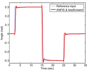
In this section, an augmented ANFIS and feedforward inverse controller is presented for control of rigid body motion of the TRMS system to enhance the tracking performance of the TRMS in hovering position as shown in Figure 8. A Sugeno fuzzy logic controller is used to enhance the tracking performance of the controller in the augmented and feedforward inverse control scheme. The generated optimal control signal is then trained using ANFIS technique. The proposed ANFIS scheme is able to precisely learn the control relation between input-output training data generated by the learning algorithm. It was also found that the ANFIS controller was able to learn fuzzy logic rules and parameters accurately. The controller learning optimization has been done offline. Finally the new ANFIS controller
block was added to the whole control scheme to provide an online control scheme for the whole system. The ANFIS controller approach gives the TRMS plant the ability to adapt with the changing conditions in the environment. A plant model equipped with the intelligent controller is able to train itself with the new data to update its parameters, and as a consequence is able to change its behaviour accordingly. The total input that enters the plant is the sum of the feedback control signal and the feedforward control signal which is calculated from the inverse dynamic model. The model uses the desired pitch angle as the input and the output is the main voltage.
Figure 9 shows that the output response of an augmented ANFIS and feedforward inverse controller is better than using direct inverse-model control. The value of overshoot has been reduced by 5.9% and the settling time also has been reduced for up to 8 second.
Inverse Model TRMS Model ) (t ref α
+
u(t) α(t) ∑ ANFIS Control ∑+
+
Feedforward controlFigure 8. The block diagram of the augmented ANFIS and feedforward inverse control 0 5 10 15 20 25 30 35 -0.3 -0.2 -0.1 0 0.1 0.2 0.3 Time (sec) A ngl e (rad) Reference input ANFIS & feedforward
Figure 9. Closed loop response of the augmented ANFIS and feedforward inverse control to a reference input
C. Augmented ANFIS and feedback inverse control In the absence of model inversion error, the combination of feedback inverse control loop together with a highpass filter design is applied to augment the vertical attitude control system, see Figure 10. The cutoff frequency value for both high pass filter and low pass filter is set to be 0.15Hz.
From previous study [1], [2], the main dominant mode of the TRMS is at 0.349Hz.
The control structure in Figure 10 comprises two control loops. The first loop (Loop 1) will correspond to a standard ANFIS controller, with a low pass filter (LPF) located at the feedback loop. The main purpose of the LPF is to reject frequencies above 0.15Hz including the main resonance mode of the system so that the first loop will solely concentrate on control of the rigid body motion of the system.
The second loop (Loop 2) is a negative feedback loop where the inverse model is used as a controller to augment the hovering control of the system albeit of using the ANFIS feedback controller alone. The high pass filter (HPF) will reject the low-frequency (rigid-body) dynamics of the system. Thus, this loop will control the flexible motion dynamics (vibrations) of the system.
Inverse Model TRMS Model ) (t ref α
+
u(t) α(t) ∑ ANFIS Control ∑+
HP
F
LPF
Loop 1 Loop 2Figure 10. The block diagram of a specialised controller
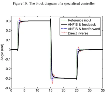
0 5 10 15 20 25 30 35 -0.4 -0.3 -0.2 -0.1 0 0.1 0.2 0.3 Time (sec) A ngl e (rad) Reference input ANFIS & feedback ANFIS & feedforward Direct inverse
Figure 11. Closed loop response of the control system to a reference input Figure 11 shows a comparison of using the three inverse-model based controllers presented in this work. It is evident from the output response that the direct inverse-model control had a relatively poor performance and the augmented ANFIS and feedforward inverse controller improved the performance. However, the augmented ANFIS and feedback inverse controller scheme gave superior performance with no
overshoot and faster settling time, and hence leads to perfect response.
VI. CONCLUSION
In this work, a scrutinized investigation on dynamic inverse model based control approach has been developed and applied to a TRMS in simulated 1 DOF hovering motion. An inverse model control approach with ANFIS adaptation in feedforward and feedback configurations has been developed. It has been demonstrated that the inverse model control has great potential in controlling the flexible dynamics of the system.
REFERENCES
[1] [1] J. V. R. Prasad and A. M. Lipp, "Synthesis of a helicopter nonlinear flight controller using approximate model inversion,"
Mathematical and Computer Modelling, Vol. 18, No. 3-4, pp. 89-100, 1993.
[2] [2] K. Danai, "Helicopter rotor tuning," in Vibration and Shock Handbook, C. W. d. Silva, Ed.: Taylor & Francis Ltd, CRC Press, 2005.
[3] [3] Z. Shuo and Z. Jihong, "Adaptive Compensated Dynamic Inversion Control for a Helicopter with Approximate Mathematical Model," presented at International Conference on Computational Intelligence for Modelling, Control and Automation, Sydney, Australia, 2006, pp. 208-208.
[4] [4] Y. Cao, Y. Chen, K. Y. and, and C. Jin, "Nonlinear inverse dynamics control of the aircraft in the presence of windshear,"
Aircraft Engineering and Aerospace Technology, Vol. 76, No. 6, pp. 592-599, 2004.
[5] [5] G. Haïat, A. Lhémery, P. Calmon, and F. Lasserre, "A model-based inverse method for positioning scatterers in a cladded component inspected by ultrasonic waves,"Ultrasonics, Vol. 43, No. 8, pp. 619-628, 2005.
[6] [6] A. Rahideh, H. Shaheed, and A. Bajodah, "Adaptive non-linear model inversion control of a twin rotor multi-input multi-output system using artificial intelligence,"Proceedings of the Institution of
Mechanical Engineers, Part G: Journal of Aerospace Engineering,
Vol. 221, No. 3, pp. 343-351, 2007.
[7] [7] S. F. Toha, M. O. Tokhi, and Z. Hussain, "ANFIS modeling of a twin rotor system," presented at UKACC International Conference on Control 2008 (UKACC08), Manchester, UK, 2008, pp. P125.pdf. [8] [8] S. F. Toha and M. O. Tokhi, "MLP and Elman recurrent neural
network modelling for the TRMS," presented at Cybernetic Intelligent Systems, 2008. CIS 2008. 7th IEEE International Conference on, London, UK, 2008, pp. 1-6.
[9] [9] S. F. Toha and M. O. Tokhi, "ANFIS modelling of a twin rotor system using particle swarm optimisation and RLS," presented at 8th IEEE International Conference on Cybernetic Intelligent Systems, Birmingham, United Kingdom, 2009.
[10] [10] C. Kambhampati, R. J. Craddock, M. Tham, and K. Warwick, "Inverse model control using recurrent networks,"Mathematics and Computers in Simulation, Vol. 51, No. 3-4, pp. 181-199, 2000. [11] [11] Feedback Instrument Ltd,Twin Rotor MIMO System manual
33-007-0. Sussex, UK, 1996.
[12] [12] J. S. R. Jang, "ANFIS: adaptive-network-based fuzzy inference system,"Systems, Man and Cybernetics, IEEE Transactions on, Vol. 23, No. 3, pp. 665-685, 1993.
[13] [13] S. Lee, C. Ha, and B. S. Kim, "Adaptive nonlinear control system design for helicopter robust command augmentation,"
Aerospace Science and Technology, Vol. 9, No. 3, pp. 241-251, 2005. [14] [14] F.-L. Luo and R. Unbehaun,Applied neural networks for signal
processing: Cambridge University Press, Cambridge, 1997.
111 111