Worcester Polytechnic Institute Worcester Polytechnic Institute
Digital WPI
Digital WPI
Doctoral Dissertations (All Dissertations, All
Years) Electronic Theses and Dissertations
2020-05-14
Improving the Performance of Dynamic Electromyogram-to-Force
Improving the Performance of Dynamic Electromyogram-to-Force
Models for the Hand-Wrist and Multiple Fingers
Models for the Hand-Wrist and Multiple Fingers
Berj BardizbanianWorcester Polytechnic Institute
Follow this and additional works at: https://digitalcommons.wpi.edu/etd-dissertations
Repository Citation Repository Citation
Bardizbanian, B. (2020). Improving the Performance of Dynamic Electromyogram-to-Force Models for the Hand-Wrist and Multiple Fingers. Retrieved from https://digitalcommons.wpi.edu/etd-dissertations/600
This dissertation is brought to you for free and open access by Digital WPI. It has been accepted for inclusion in
Doctoral Dissertations (All Dissertations, All Years) by an authorized administrator of Digital WPI. For more
IMPROVING THE PERFORMANCE OF DYNAMIC
ELECTROMYOGRAM-TO-FORCE MODELS FOR THE
HAND-WRIST AND MULTIPLE FINGERS
by
Berj Bardizbanian
A Thesis
Submitted to the Faculty
of the
WORCESTER POLYTECHNIC INSTITUTE
in partial fulfillment of the requirements for the
Degree of Doctor of Philosophy
in
Electrical and Computer Engineering,
2020
APPROVED:
____________________________
Professor Edward A. Clancy, Major Advisor, WPI ECE
____________________________Professor Xinming Huang, Committee Member, WPI ECE
____________________________Todd R. Farrell, Ph.D., Committee Member, Liberating Technologies, Inc.,
Holliston, MA
Abstract
Relating surface electromyogram (EMG) activity to force/torque models is used in many areas including: prosthesis control systems, to regulate direction and speed of movement in reaching and matching tasks; clinical biomechanics, to assess muscle deficiency and effort levels; and ergonomics analysis, to assess risk of work-related injury such as back pain, fatigue and skill tests. This thesis work concentrated on improving the performance of dynamic EMG-to-force models for the hand-wrist and multiple fingers. My contributions include: 1) rapid calibration of dynamic hand-wrist EMG-force models using a minimum number of electrodes, 2) efficiently training two degree of freedom (DoF) hand-wrist EMG-force models, and 3) estimating individual and combined fingertip forces from forearm EMG during constant-pose, force-varying tasks.
My calibration approach for hand-wrist EMG-force models optimized three main factors for 1-DoF and 2-DoF tasks: training duration (14, 22, 30, 38, 44, 52, 60, 68, 76 s), number of electrodes (2 through 16), and model forms (subject-specific, DoF-specific, universal). The results show that training duration can be reduced from historical 76 s to 40–60 s without statistically affecting the average error for both 1-DoF and 2-DoF tasks. Reducing the number of electrodes depended on the number of DoFs. One-DoF models can be reduced to 2 electrodes with average test error range of 8.3–9.2% maximum voluntary contraction (MVC), depending on the DoF (e.g., flexion-extension, radial-ulnar deviation, pronation-supination, open-close). Additionally, 2-DoF models can be reduced to 6 electrodes with average error of 7.17–9.21 %MVC. Subject-specific models had the lowest error for 1-DoF tasks while DoF-specific and universal were the lowest for 2-DoF tasks.
In the EMG-finger project, we studied independent contraction of one, two, three or four fingers (thumb excluded), as well as contraction of four fingers in unison. Using regression, we found that a pseudo-inverse tolerance (ratio of largest to smallest singular value) of 0.01 was optimal. Lower values produced erratic models and higher values produced models with higher errors. EMG-force errors using one finger ranged from 2.5–3.8 %MVC, using the optimal pseudo-inverse tolerance. With additional fingers (two, three or four), the average error ranged from 5–8 %MVC. When four fingers contracted in unison, the average error was 4.3 %MVC.
Additionally, I participated in two team projects—EMG-force dynamic models about the elbow and relating forearm muscle EMG to finger force during slowly force varying contractions. This work is also described herein.
Acknowledgements
First and Foremost, I am greatly thankful to my research advisor, Dr. Edward A. Clancy, for his support and guidance thru my academic years at WPI. There is no word to describe his friendly, honest and patient characters. He was the one who lighten my path to success at WPI and I am honored to know somebody like him in my life.
Thank you to my committee, Professor Xinming Huang and D. Todd Farrell, for your advice and feedback on this thesis.
Thank you to my research partners, Chenyun Dai, Ziling Zhu and Jianan Li who gave me a lot of help on my research.
Thank you to Jennifer Keating for her support and friendship thru our Finger-EMG project.
Thank you to my wife, Marghrit, for your patience and support. For taking upon you the caring of our kids during my absence. For understanding the challenges that I was going thru balancing work, family and study.
Thank you to my kids, Noushig, Armig and Chris for embracing my situation as a father, care provider and student. For acknowledging the fact that life requires sacrifice to earn what you are looking for.
Thank you, my parents, Mom and Dad who gave me love and shelter, for teaching me to stand on my own, for you always cared for me. I wish you were with me. Hope you can read this from the New Jerusalem.
And finally Thank you God who strengthen me and held my hand thru all my difficult times “So do not fear, for I am with you; do not be dismayed, for I am your God. I will strengthen you and help you; I will uphold you with my righteous right hand” (Isaiah: 41:10)
Table of Contents
Abstract ... 2
Acknowledgements ... 3
Chapter 1: Background and Introduction ... 14
1.1 Background on Electromyography (EMG) ... 14
1.2 EMG Processing ... 22
1.3 My Thesis Contributions ... 27
1.3.1 Finger Project ... 27
1.3.2 Hand-Wrist Project ... 29
1.3.3 Collaborative Work ... 30
1.4 Summary of My Ph. D. Research and Introduction to Remaining Chapters ... 31
REFERENCES ... 32
Chapter 2: Estimating Individual and Combined Fingertip Forces From Forearm EMG During Constant-Pose, Force-Varying Tasks ... 38
2.1 Introduction ... 38
2.2 Methods ... 40
2.2.1 Experimental Apparatus and Subject Set-Up ... 40
2.2.2 Experimental Data Collection ... 41
2.2.3 Analysis—Signal Processing ... 41
2.2.4 Analysis—Models... 42
2.2.5 Statistics ... 43
2.3 Results ... 43
2.3.1 One Independent Finger Models ... 43
2.3.2 Two Independent Finger Models ... 43
2.3.3 Three Independent Finger Models ... 45
2.3.4 Four Independent Finger Models ... 45
2.3.5 Four-Finger “Grip” Models ... 47
2.4 Discussion ... 47
Chapter 3: Calibration of Dynamic Hand-Wrist EMG-Force Models Using a Minimum Number of Electrodes ... 49 3.1 Introduction ... 49 3.2 Methods ... 49 3.3 Results ... 50 REFERENCES ... 52
Chapter 4: Advancement In Rapid Calibration of Dynamic EMG-Force Models At The Hand/Wrist Using a Minimum Number of Electrodes ... 53
4.1 Abstract ... 53
4.2 Methods ... 53
4.3 Results ... 54
4.4 Conclusion ... 54
Chapter 5: Efficiently Training Two-DoF Hand-Wrist EMG-Force Models ... 55
5.1 Abstract ... 55
5.2 Introduction ... 56
5.3 Methods ... 57
5.3.1 Experimental Data and Apparatus ... 57
5.3.2 Analysis: Signal Preprocessing ... 58
5.3.3 Analysis: One-DoF Models ... 59
5.3.4 Analysis: Two-DoF Models ... 61
5.3.5 Statistics ... 61
5.4 Results ... 62
5.4.1 One-DoF Models ... 62
5.4.2 Two-DoF Models Assessed on Two-DoF Trials ... 63
5.5 Discussion ... 64
5.5.1 Parameter Selection for Efficient EMG-Force Training ... 64
5.5.2 Limitations and Extensions ... 65
REFERENCES ... 66
Chapter 6: Comparison Of Constant-Posture Force-Varying EMG-Force Dynamic Models About The Elbow ... 70
6.1 Abstract ... 70
6.2 Introduction ... 71
6.3 Methods ... 73
6.3.1 Experimental Subjects, Apparatus and Methods ... 73
6.3.2 Methods of Analysis ... 74
6.4 Results ... 77
6.4.1 Baseline Technique vs. One Improvement Technique ... 78
6.4.2 One Improvement Technique vs. Two ... 82
6.5 Discussion ... 86
6.6 Conclusion ... 90
REFERENCES ... 91
Appendix 1: Test Setup Validation ... 97
A-1.1 Electrode Amplifier ... 97
A-1.1.1 Executive Summary ... 97
A-1.1.2 Electrode Design ... 97
A-1.1.3 Electrode Manufacturing ... 99
A-1.1.4 Materials: ... 100
A-1.1.5 Tools and Equipment: ... 101
A-1.1.6 Work Instructions: ... 101
A-1.1.7 Testing the Soldered PCB ... 110
A-1.1.8 DB9 and RJ45 Connector Testing ... 110
A-1.2 Bridge Amplifier ... 111
A-1.4 Calibration for Finger and Grips LABVIEW VI ... 111
Appendix 2: Long-form EMG-Finger paper... 146
A-2.1 Introduction ... 112
A-2.2 Data Acquisition ... 114
A-2.2.1 EMG Signal ... 114
A-2.2.2 Force Signal ... 116
A-2.3 Subject Interface ... 117
A-2.3.1 Surface EMG Amplifier Placement ... 118
A-2.3.2 Finger Restraint Apparatus ... 120
A-2.3.3. Virtual Instruments ... 122
A-2.4 Statistical Methods ... 126
A-2.5 Results and Discussion... 127
REFERENCES ... 138
Appendix 3: Long-form EMG-Finger Paper Figures ... 146
Appendix 4: Long-form Hand-Wrist paper ... 146
A-4.1 Methods ... 146
A-4.1.1 Experimental Data and Apparatus ... 146
A-4.1.2 Analysis—Signal Preprocessing ... 148
A-4.1.3 Analysis—One-DoF Models ... 148
A-4.1.4 Analysis—Two-DoF Models ... 151
A-4.2 Statistics ... 151
A-4.3 Results ... 152
A-4.3.1 One-DoF Models, Backward Selected Locations ... 152
A-4.3.2. One-DoF Models, Eight Pre-Selected Locations ... 155
A-4.3.4 Two-DoF Models, Eight Pre-Selected Locations ... 160
Appendix 5: Backward Selection Electrodes’ Comparison ... 163
Appendix 6: Clinical Documents ... 167
A-6.1: Informed Consent... 167
A-6.2: SOP-001 Procedure ... 170
A-6.3: Subject Questionnaire ... 171
A-6.4: Source Document for Clinical Procedure ... 173
Table of Figures
Fig. 1.1. Illustration of concentric, eccentric and isometric contractions [Betts et al., 2017] ... 15
Fig. 1.2. Skeletal Muscle Length-Tension Curves [Barrett et al., 2012] ... 16
Fig. 1.3. The structure of a skeletal muscle [Betts et al., 2017] ... 16
Fig. 1.4. Electrical activity of one individual motor unit [Marieb, 2008] ... 18
Fig. 1.5. Schematic representation of generation of a MUAP [Basmajian and DeLuca, 1985] ... 19
Fig. 1.6. Schematic for motor unit action potential (MUAP) train [DeLuca, 1979] ... 20
Fig. 1.7. Schematic representation of EMG signal derived from the sum of MUAP trains [DeLuca, 1975] ... 20
Fig. 1.8. Surface bipolar electrode-amplifier and its electrical circuit [Salini et al., 2003] ... 22
Fig. 1.9. Indwelling electrodes [Stalberg, 1980] ... 22
Fig. 1.10. Raw EMG signal (in grey) and its EMG amplitude (in blue) [Clancy, 1991] ... 23
Fig. 1.11. Functional Mathematical model of EMG [Hogan and Mann 1980a] ... 24
Fig. 1.12. Detailed signal processing procedure of EMG amplitude estimation [Clancy et al. 2002] ... 25
Fig. 2.1. Index finger secured to restraint. ... 39
Fig. 2.2. Average error (%MVC) for one-finger models. ... 44
Fig. 2.3. Average error (%MVC) for two finger models. ... 44
Fig. 2.4. Average error (%MVC) for three-finger models. ... 45
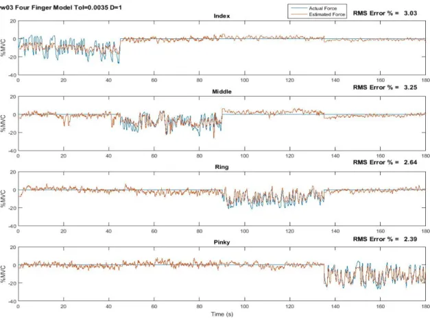
Fig. 2.5. Estimated force versus actual force, four-finger study ... 46
Fig. 2.6. Average error (%MVC) for four-finger models. ... 46
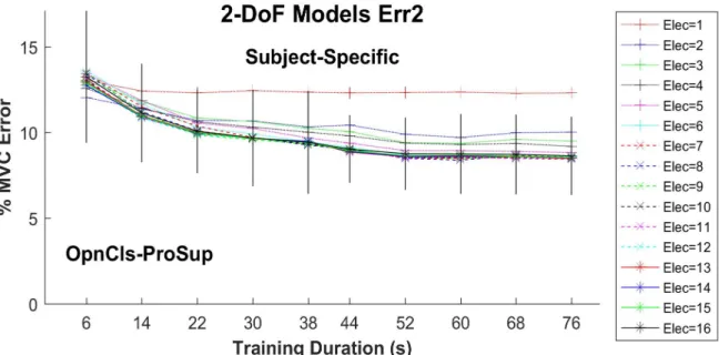
Fig. 3.1. Two-DoF summary error results. ... 51
Fig. 5.1. Each of 144 magnitude responses of the 1-DoF models is shown in grey . Thick blue line is the average and thin red line is the universal FIR filter fit to these responses. ... 60
Fig. 5.2. One-DoF summary results for each DoF vs. training duration. ... 600
Fig. 5.3. Two-DoF summary results for each DoF pair vs. training duration, when assessing on 2-DoF trials. . ... 63
Fig. 6.1. Subject seated in the experimental apparatus . ... 74
Fig. 6.2. Example EMGσ-torque estimation results for selected models. ... 78 Fig. 6.3. Baseline Model vs. EMG Channel Selection ... Error! Bookmark not defined.
Fig. 6.4. Baseline Model vs. Feature Set ... Error! Bookmark not defined.
Fig. 6.5. Baseline Model vs. Power-Law Model ... 822
Fig. 6.6. Four-Channel EMG. ... Error! Bookmark not defined. Fig. 6.7. EMGσ Feature ... Error! Bookmark not defined.4 Fig. 6.8. Quadratic Model ... Error! Bookmark not defined.5 Fig. A-1.1. Electrode circuitry ... 97
Fig. A-1.2. Ultra-flex cable configuration ... 98
Fig. A-1.3. PCB with electronic components, electrode assemblies, and ultra-flex cable ... 98
Fig. A-1.4. PCB top and bottom copper layers ... 99
Fig. A-1.5. PCB with resistor, capacitors and AD 620 ... 102
Fig. A-1.6. PCB with electronics, screws, nuts, and washers ... 103
Fig. A-1.7. Model with plywood side walls... 103
Fig. A-1.8. Green Rubber Mold ... 104
Fig. A-1.9. Ultra-Flex wire ... 104
Fig. A-1.10. PCB with electronic components, electrode assemblies, and ultra-flex cable ... 105
Fig. A-1.11. Heat-shrink tubing added over cable ... 105
Fig. A-1.12. DP460 or DP420 Applicator Gun ... 106
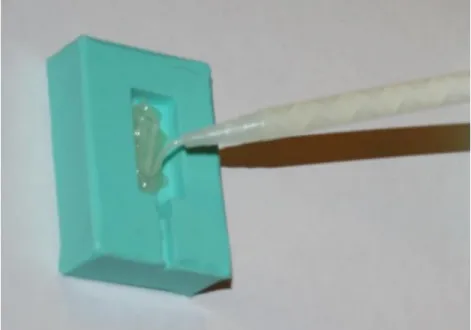
Fig. A-1.13. Filling the base layer of epoxy in mold ... 107
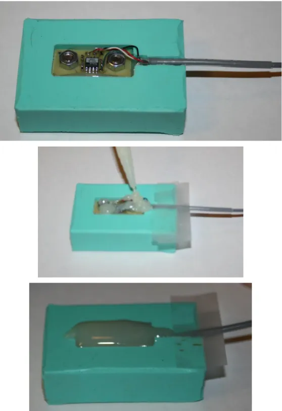
Fig. A-1.14. Placing the PCB into the mold and pouring the epoxy ... 108
Fig. A-1.15. Final product after sanding ... 109
Fig. A-1.16. Electrode-DB9 wiring diagram ... 109
Fig. A-1.17. RJ45 to DB9 Female connector wiring Diagram ... 110
Fig. A-2. 1. EMG Signal Acquisition [Keating, 2014] ... 114
Fig. A-2. 2. Surface bipolar electrode-amplifier and its electrical circuit [Salini et al., 2003] ... 115
Fig. A-2. 3. Signal Conditioner circuit diagram [Clancy, 2013] ... 115
Fig. A-2. 4. Force Signal Acquisition [Keating, 2014] ... 116
Fig. A-2. 5. Bridge Amplifier ... 117
Fig. A-2. 6. Diagram of subject interface study [Keating, 2014] ... 117
Fig. A-2. 7. Layers of Skin [Betts, 2017]... 119
Fig. A-2. 9. Diagram of flexion and extension electrode placement with respect to forearm muscles [Marieb, 2013] ... 120 Fig. A-2. 10. Finger and Grip Apparatus [Keating, 2014] ... 121 Fig. A-2. 11. Subject Interaction screen ... 123 Fig. A-2. 12. Mean Error in MVC% for Index Finger across the study for each model, Q and
whitened/unwhitened ... 127 Fig. A-2. 13. . Estimated Force versus Actual Force for subject ww11 Middle Finger. ... 128 Fig. A-2. 14. . Mean Error in MVC% for Ring-Pinky Finger across the study for each model, Q
and whitened/unwhitened ... 129 Fig. A-2. 15. Estimated Force versus Actual Force for subject ww03 two finger study
Ring-Pinky. ... 130 Fig. A-2. 16. Mean Error in MVC% for Middle-Ring-Pinky Finger across the study for each
model, Q and whitened/unwhitened. ... 132 Fig. A-2. 17. Estimated Force versus Actual Force for subject ww03 three finger study
Middle-Ring-Pinky. ... 132 Fig. A-2. 18. Mean Error in MVC% for Four Finger across the study for each model, Q and
whitened/unwhitened. ... 134 Fig. A-2. 19. Estimated Force versus Actual Force for subject ww03 Four Finger Study. ... 134 Fig. A-2. 20. Mean Error in MVC% for Three Finger Grip across the study for each model, Q
and whitened/unwhitened. ... 136 Fig. A-2. 21. Mean Error in MVC% for Four Finger Grip across the study for each model, Q and
whitened/unwhitened. ... 137 Fig. A-3. 1. Mean Error in MVC% for Index Finger across the study for each model, Q and
whitened/unwhitened ... 139 Fig. A-3. 2. Mean Error in MVC% for Middle Finger across the study for each model, Q and
whitened/unwhitened ... 139 Fig. A-3. 3. Mean Error in MVC% for Pinky Finger across the study for each model, Q and
whitened/unwhitened ... 140 Fig. A-3. 4. Mean Error in MVC% for Ring Finger across the study for each model, Q and
Fig. A-3. 5. Mean Error in MVC% for Index-Middle Finger across the study for each model, Q and whitened/unwhitened ... 141 Fig. A-3. 6.Mean Error in MVC% for Index-Pinky Finger across the study for each model, Q and whitened/unwhitened ... 141 Fig. A-3. 7. Mean Error in MVC% for Index-Ring Finger across the study for each model, Q and
whitened/unwhitened ... 142 Fig. A-3. 8. Mean Error in MVC% for Middle-Pinky Finger across the study for each model, Q
and whitened/unwhitened ... 142 Fig. A-3. 9. Mean Error in MVC% for Middle-Ring Finger across the study for each model, Q
and whitened/unwhitened ... 143 Fig. A-3. 10. Mean Error in MVC% for Ring-Pinky Finger across the study for each model, Q
and whitened/unwhitened ... 143 Fig. A-3. 11. Mean Error in MVC% for Index-Middle-Pinky Finger across the study for each
model, Q and whitened/unwhitened ... 144 Fig. A-3. 12. Mean Error in MVC% for Index-Middle-Ring Finger across the study for each
model, Q and whitened/unwhitened ... 144 Fig. A-3. 13. Mean Error in MVC% for Index-Ring-Pinky Finger across the study for each
model, Q and whitened/unwhitened ... 145 Fig. A-3. 14. Mean Error in MVC% for Middle-Ring-Pinky Finger across the study for each
model, Q and whitened/unwhitened ... 145 Fig. A-4. 1. Force/moment measurement apparatus ... 146 Fig. A-4. 2. Each of 144 magnitude (top) and phase (bottom) responses of the 1-DoF models is
shown in grey . Thick blue lines are the averages and thin red lines are the universal FIR filter fit to these responses. ... 149 Fig. A-4. 3. One-DoF summary error results after calibrating dynamic models to each subject 152 Fig. A-4. 4. One-DoF summary error results after calibrating dynamic models to each DoF ... 153 Fig. A-4. 5. One-DoF summary error results after calibrating dynamic models to universal filter
... 153 Fig. A-4. 6. Rank order of errors (left lower error) for different models and DoFs. ... 154 Fig. A-4. 7. Statistical differences between durations. ... 155
Fig. A-4. 8. One-DoF summary error results for preselected eight electrodes versus duration, presented separately for each DoF as a function of training duration. ... 156 Fig. A-4. 9. Two-DoF summary error results after calibrating dynamic models to each subject157 Fig. A-4. 10. Two-DoF summary error results after calibrating dynamic models to each DoF pair
... 157 Fig. A-4. 11. Two-DoF summary error results after calibrating dynamic models to universal
filter. ... 158 Fig. A-4. 12. Statistical differences between number of electrodes. ... 159 Fig. A-4. 13. Statistical differences between durations . ... 160 Fig. A-4. 14. Two-DoF summary error results for preselected eight electrodes versus duration,
1.
Chapter 1: Background and Introduction
1.1
Background on Electromyography (EMG)
Electromyography, which is the study of muscle function through inquiry of the electrical signal of skeletal muscles, has been of scientific interest since 1666 [Basmajian and DeLuca, 1985]. It incorporates central control strategies, signal transmission along nerve fibers and, through chains of complex biochemical events, the production of forces acting on the tendons of the agonist and/or antagonist muscles, moving the bones.
Body movement is a result of muscle contraction [Marieb and Hoehn, 2013]. The type of contraction depends on the muscle tension (force exerted on an object) and load (opposing force exerted on muscle by an object). Two frequently-studied types of contraction are isotonic and isometric (Fig. 1.1). Isotonic contraction involves either concentric or eccentric contraction. A contraction in which the muscle fibers shorten to create force is called concentric. However, when the muscle lengthens during the contraction, then an eccentric contraction is taking place.
An isometric contraction, on the other hand, is one in which the muscle does not change length while contracting. In an isometric contraction, tension is developed but a load is not moved (e.g., pushing against a wall). During this kind of contraction, the maximum tension for the muscle in use can be reached, but the muscle only shortens slightly from applying tension to tendons and ligaments.
Both active and passive muscle force depend on the length of the muscle. Active force peaks when the muscle is around its resting length, and decreases when the muscle is shortened or lengthened (Fig. 1.2). Passive force, on the other hand, works like a rubber band; it’s minimal when the muscle is shortened, and increases exponentially as the muscle lengthens.
Fig. 1.1. Illustration of concentric, eccentric and isometric contractions [Betts et al., 2017]
Skeletal muscle is made up of bundles of muscle fibers (Fig. 1.3), which in turn are bundles of muscle cells. Each muscle is surrounded by a connective tissue sheath called the epimysium. Fascia, connective tissue outside the epimysium, surrounds and separates the muscles. Portions of the epimysium project inward to divide the muscle into compartments. Each compartment contains a bundle of muscle fibers. Each bundle of muscle fibers is called a fasciculus and is surrounded by a layer of connective tissue called the perimysium. Within the fasciculus, each individual muscle cell, called a muscle fiber, is surrounded by connective tissue called the endomysium.
Fig. 1.2. Skeletal Muscle Length-Tension Curves [Barrett et al., 2012]
Myofibrils (muscle fibrils) are composed of long proteins including actin, myosin, and titin, and other proteins that hold them together. These proteins are organized into thick and thin filaments called myofilaments, which repeat along the length of the myofibril in sections called sarcomeres. Muscles contract by sliding the thick (myosin) and thin (actin) filaments along each other, thereby shortening the sarcomere length. Energy that is produced in cells by adenosine triphosphate is called ATP energy. ATP energy is essential for many living processes, including muscle contraction and nerve impulses.
People have two general types of skeletal muscle fibers: slow-twitch (type I) and fast-twitch (type II). Slow-fast-twitch muscles tend to be the deeper muscle fibers with slower conduction velocity. They generate more ATP from aerobic metabolism; have slower, less forceful contraction; and are slower to fatigue. Fast twitch muscle fibers produce larger action potentials than those of slow twitch fibers. These muscle fibers fatigue faster but are used in powerful bursts of movements like sprinting. Fast-twitch muscles generate more ATP from glucose (thus, lactic acid is a by-product); produce quicker, more forceful contraction; and are faster to fatigue. The phasic muscles responsible for generating movement in the body contain a higher density of fast-twitch fibers. Strength and power training can increase the number of fast-fast-twitch muscle fibers recruited for a specific movement.
Motor neurons electro-chemically activate muscle fibers. In resting conditions, the concentration of sodium is relatively high outside the muscle cell membrane and relatively low inside the fiber, while potassium concentration is relatively low outside the membrane and relatively high inside of the muscle. When excited via depolarization of the muscle membrane, these relative concentrations flip polarity. As a result, fibers depolarize—which instantiates fiber mechanical contraction and creates a changing electromagnetic field. EMG is the recording of this electromagnetic field, as it propagates within muscle or on the skin surface.
Fig. 1.4 shows the time course of depolarization-repolarization in one individual muscle fiber. The rest potential is often around –70 mV, which is based on the concentration of sodium, potassium and chloride in body cells and fluid. When muscle fibers are activated, the action potential peaks at around +30 mV. The duration of one action potential is usually 2–4 ms or longer. When the overall muscle continues to contract, the same motor unit will successively generate a series of action potentials with quite similar shape.
Fig. 1.4. Electrical activity of one individual motor unit [Marieb, 2008]
A motor unit consists of a motoneuron and all of its innervated muscle fibers. When a motoneuron is activated (or “fired”), it results in the near simultaneous discharge of many muscle fibers. The summed electrical activity of all muscle fibers is called the motor unit action potential (MUAP) (Fig. 1.5). The number of motor units recruited has a large impact on the amplitude of EMG. Also, the average frequency with which motor units are activated is called the firing rate. Motor units have initial firing rates of 5–10 pulses per second. As the demand for force increases, firing rate increases and it might exceed 60 pulses per second. For an individual motor unit (and, in general, between motor units) successive firing times are mostly independent and random at low force levels and become more correlated at higher force levels. Muscular force is affected by the pattern of muscular activation, including doublet firing (two successive firings of the same motor in a very short time span, such as 20 ms) or simultaneously fired motor units.
Fig. 1.5. Schematic representation of generation of a motor unit action potential (MUAP) from it constituent muscle fibers [Basmajian and DeLuca, 1985]
One motor unit always generates a similarly shaped action potential for healthy muscles (Fig. 1.6), while different motor units typically produce different action potential shapes; albeit these distinct shapes are still peaked in shape. The shape of a motor unit action potential sometimes may vary due to muscle fatigue or disease [Basmajian and DeLuca, 1985]. When muscle contraction level increases, several different motor units may discharge at the same time. Fig. 1.7 shows this case as the superposition of potentials from individual motor units. When the muscle generates force, each motor unit produces successive motor unit action potentials. This process can be modeled as: the nerve sends a series of stimuli (an impulse train) through its innervated muscle fibers. Then, the EMG output can be regarded as an impulse response train. When many motor units are active at the same time, the EMG recording would be the summation of these impulse response trains. Therefore, the EMG recording looks like a random Gaussian process (i.e., the sum of many mostly-independent, sufficiently identically shaped pulses). Mathematically, equation 1 shows the superposition model of MUAP. Signal ui(t) is the result of passing the
impulse trains through the shape of the MUAP, h(t) (Fig. 1.6), f denotes the constant force value, and s is the total number of MUAP’s present (De Luca and Forrest, 1973). (The firing rate is defined as the average number of MUAPs per second in a MUAP train.)
, = ,
Equation 1: Model of MUAP
Fig. 1.6. Schematic for motor unit action potential (MUAP) train [DeLuca, 1979]
Fig. 1.7. Schematic representation of EMG signal derived from the sum of MUAP trains [DeLuca, 1975]
Merlo et al. [Merlo et al., 2000] modeled the surface EMG signal, , as:
= + = − +
Equation 2: Model of surface EMG signal by Merlo et al. [2000]
where is an amplitude factor for the jth motor unit,
f()
is the shape of the action potentialdischarge,
θ
ijis the
ith time at which the MUAP occurs,α
j is a scaling factor, and
n(t)
is additive noise.The sEMG signal is dependent on the level and duration of contraction, the state of the contraction (static or dynamic), fatigue, and sweat from the skin. The maximum level that a skeletal muscle can contract to is referred to as maximum voluntary contraction (MVC), and contraction levels are typically referred to by the percentage of MVC that they represent. Studies have found that the distribution of the EMG signal is more sharply peaked near zero than a Gaussian distribution, and that at low contraction levels, the signal is more likely to be best modeled as a zero mean Laplacian process [Clancy et. al 2002, Wang et. al 2019].
EMG is acquired either using surface electrodes (Fig. 1.8) or indwelling electrodes (Fig. 1.9). These electrodes are either monopolar (potential difference with respect to a common reference location, with the common reference location often being electrically inactive) or bipolar (potential difference with respect to two electrically active locations). Surface electrodes are a noninvasive and easy to apply method of recording. It involves applying electrolyte gel and rubbing into the skin in lab applications so that it is absorbed to the stratum mucosum to make contact with the derma. Then, the electrode is placed on the muscle under study and held in place by tape or some other means. Disadvantages of using these electrodes include that they can also record EMG from unrelated muscles that is mixed in with the signal of interest (a phenomenon referred to as cross talk), are affected by sweat (if not gelled), and may be more susceptible to motion artifact. Indwelling electrodes record EMG either using single needle or two wires inserted within the muscle. Indwelling EMG has great diagnostic value but is invasive, not appropriate for chronic applications, can be painful, and not appropriate for monitoring many dynamic contractions as occur in human movement.
Fig. 1.8. Surface bipolar electrode-amplifier and its electrical circuit [Salini et al., 2003]
Fig. 1.9. Indwelling electrodes [Stalberg, 1980]
1.2
EMG Processing
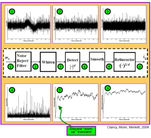
Surface EMG was processed across our experiments using five stages: (1) noise rejection/filtering, (2) multiple-channel combination (including gain scaling), (3) demodulation, (4) smoothing and (5) relinearization [Clancy et al., 2002]. This process estimates the time-varying signal standard deviation. The standard deviation of the electrical activity generated by a muscle is commonly referred to as the amplitude of the EMG, which measures the intensity of muscular activation level. Fig. 1.10 shows an example raw EMG signal (in grey) and its EMG amplitude (in blue). When many motor units contract at the same time, the surface EMG signal is the sum of their impulse response trains and can be regarded as an amplitude modulated, zero-mean, random
Gaussian process (see Fig. 1.11). The math expression for this Gaussian process model is: [ ] = [ ]∙ [ ], where n is the discrete-time sample index, [ ] is raw EMG signal, [ ] is EMG amplitude (i.e., standard deviation) and [ ] is a random process with unit variance. One important feature which can be extracted from the processed EMG signal is EMG amplitude.
Fig. 1.11. Functional Mathematical model of EMG [Hogan and Mann 1980a]
Fig. 1.12 shows detailed signal processing steps for EMG amplitude estimation. Noise is generated from two sources: inherent and interference [Kamen and Gabriel, 2010]. Inherent noises are initiated at either electrode to skin and electrode to metal interfaces or amplifier noise due to thermal (resistive) and 1/f noises (amplitude is greatest at low frequency, then deceases according to the function 1/f) [Huigen et al., 2002]. Interference noise is induced from the power line (60 Hz) and all the harmonics. Interference is also introduced at lower frequencies due to motion artifacts. In order to attenuate noise, the EMG is highpass filtered at 15 Hz using a 5th order Butterworth
filter followed by an IIR notch filter of 1 Hz bandwidth, centered at 60 Hz. To achieve zero phase filtering, forward and reverse time filters were applied off-line. This filtering is followed by a first order demodulation for signal rectification. After demodulation, EMG signals were passed through a noncausal, low pass 9th order Chebyshev Type 1 lowpass filter with an effective cutoff frequency
of 0.8*20.48Hz= 16.4 Hz and decimated by a factor of 100, producing a resampled frequency of 40.96 Hz. Finally, relinearization inverts the power law applied during the demodulation stage, returning the signal to units of EMG amplitude.
Fig. 1.12. Detailed signal processing procedure of EMG amplitude estimation [Clancy et al. 2002]
EMG amplitude from relevant muscles can be related to one or more joint forces (or moments) using various methods of system identification. Various system identification methods are in use, including least squares and neural network/machine learning approaches [An et al., 1983; Clancy and Hogan, 1997; Clancy et al., 2012; Doheny et al., 2008; Hasan and Enoka, 1985; Heckathorne and Childress, 1981; Hof and Van den Berg, 1981; Hogan and Mann, 1980b; Inman et al., 1952; Lawrence and DeLuca, 1983; Sanger, 2007; Shin et al., 2009; Solomonow et al., 1986; Staudenmann et al., 2009; Thelen et al., 1994; Vredenbregt and Rau, 1973; Staudenmann et al., 2010 ]. This relation provides a non-invasive tool for applications in many different fields, such as myoelectric control of prosthesis [Parker et al., 2006], clinical biomechanics [Disselhorst-Klug et al., 2009; Doorenbosch and Harlaar, 2003], EMG biofeedback for rehabilitation [Armagan et al., 2003; Holtermann et al., 2010], ergonomic analysis/ task analysis [Hagg et al., 2004; Kumar and Mital, 1996], biomechanical modeling [Karlsson et al., 1992], and measurement in motion control studies [Fukuda et al., 2003].
The EMG to force model that we used throughout our entire project is based on the least squares approach. Equation 3 shows force output at the fingertips or hand-wrist using both linear and nonlinear FIR EMG-force modeling. The model structure was a polynomial nonlinear model of degree D (nonlinear when D>1), the equation for which is shown below [Press et al., 1994]:
[ ] = "#,$,%&#%[ − '] ( $ ) # * %
Equation 3: EMG-Force Model
• TE-F: Ext-Flx force (or Rad-Uln or Pro-Sup or …) • m: Decimated discrete time sample index
• E: Number of electrodes (initially set to 16) • Q: Number of time lags (Q=20, 30, 40) • ce,q,d: Fit coefficients
•
σ
e: EMG amplitude • D: model order This model can be written as:+ = , + -../.
Equation 4: Linear Least squares EMG-force model
•
0
: design matrix •1
: fit coefficient vector • b : output vectorThe solution to this equation is found by minimizing errors in the least square sense by minimizing the square distance between the data and signal vectors through a linear combination of the columns of A [Kay, 1993].
2 ‖ + − ,‖4
Equation 5: Linear Least error minimization
+ = 5 5, = 6,
Equation 6: Calculation of fit coefficients via singular value decomposition to find the pseudo-inverse
where A†is the Moore-Penrose pseudo-inverse of A, which uses singular value decomposition to compute A†. When calculating A†, the ratio between each individual singular value to the
maximum singular value in the design matrix A is limited by a tolerance (Tol). Singular values and vectors below this value are replaced with zero values/vectors after calculating the inverse in the middle section of the above equation [Press et al., 1994].
1.3
My Thesis Contributions
This section introduces my contributions for each of my projects. The projects in which I was the lead investigator during my Ph.D. study were the dynamic-force finger EMG-to-torque with improved methods project, dynamic-force hand-wrist EMG-to-torque with improved methods project for 1-DoF and 2-DoF models. This latter work also included efficiently calibrating and training the EMG-force hand-wrist models.
1.3.1 Finger Project
This thesis research focused on developing signal processing methods that could eventually increase the functionality of prostheses worn by amputees, as well as rehabilitation orthoses worn by stroke victims during rehabilitation. In each case, this thesis investigated the relationship between muscle electrical activity and forces exerted by upper limb.
For the EMG-force work involving the fingers, EMG signals from the forearm were collected on 19 healthy subjects during constant-posture force-varying contractions. Subjects had no known neuromuscular deficits of their right hand, arm, or shoulder. Contraction trials ranged between 30% maximum voluntary contraction (MVC) flexion and 30% MVC extension, and EMG signals were acquired using 12 bipolar surface EMG electrode-amplifiers mounted circumferentially around the forearm. Force was collected using a 100 pound load cell in contact with one or more fingertip. A model was developed to relate EMG amplitude to forces in the fingertip(s) and model performance was compared across all 19 subjects. Deliverables of this
project include a large (N=19) dataset (EMG and force recordings) in the forearm/fingers to facilitate the development of signal processing methods that might lead to increased dexterity in prosthetics and orthotics, comprised of:
• Force-varying contractions of each of four fingers (1 Hz bandwidth).
• Additional data related to contraction of multiple fingers at the same time.
• Characterization of model performance for force-varying data versus:
o The number of electrodes (1 through 12) o Model order (D=1, 2)
o The lag time (Q=20, 30, 40) o Filter (whitened, unwhitened) o Different tolerance values 0 thru 0.1
Previous literature studies: Existing commercial EMG-controlled prosthetics are mostly limited to rudimentary control: hand close/open/off fixed velocity (Parker et al., 2006) and one degree of freedom of proportional control (Smith et al., 2008). Also, researchers studied classification schemes for discriminating between hand-wrist functions and individual finger movements (Castellini et al., 2009; Khushaba et al., 2012). In our lab, fingertip force estimation from forearm muscle electrical activity from three subjects using electrode arrays of 64 channels was studied by Pu Liu (Liu et al., 2011, 2013). She collected constant-posture, slowly force-varying contraction data and her results showed evidence that surface EMG activity from the forearm encodes multiple degrees of freedom of proportional control information that may be sufficient for use in controlling prosthetic wrists, hands and/or fingers – at least when tested on intact subjects [ Liu, 2014].
My contribution in this field: We used 12 bipolar surface electrodes and expanded previous work done by Liu to study 19 more subjects instead of the three she studied. Also, we studied multiple finger models; two independent fingers, three independent fingers and four independent fingers in addition to three finger grip and four finger grip models. (In “grip” models, only one total applied force was measured, not individual finger forces.) Also, we collected data from constant-posture, dynamic force varying contractions using conventional surface electrodes. Our goal was to study how the EMG-force error changes with pseudo-inverse tolerance values and which model yields the lowest error. We found out that the one finger model error ranges from 2.5–3.8 %MVC and
(two, three, four) independent finger models averaged error from 5–8 %MVC. Four finger grip EMG-force error averaged 4.3 %MVC.
1.3.2
Hand-Wrist Project
For EMG-force work involving the hand-wrist, dynamic hand-wrist data had been previously acquired from ten able-bodied subjects [Dai, 2016]. Sixteen conventional bipolar electrodes were mounted circumferentially about the proximal forearm. The hand was secured to a load cell to measure wrist extension-flexion, radial-ulnar deviation or pronation-supination forces. The fingers were secured to a second load cell to measure hand open-close. One-DoF and 2-DoF dynamic contractions (40 s in duration) were collected. The initial 2 s of processed data trials were discarded to compensate for startup transients. Contraction trials ranged between 30% MVC flexion and 30% MVC extension. Backward stepwise selection of the training data sequentially reduced the number of electrodes. RMS error on two separate test trials was evaluated at each step. Training duration was then progressively decreased.
Previous literature studies: Myoelectric prostheses have used surface electromyogram activity from residual muscles to control prosthesis movement, thereby realizing partial replacement of function. Parker et al. (Parker et al., 2006) used one degree of freedom with and without proportional control at a time, with mode switching. Other researchers (Englehart and Hudgins, 2003; Parker, Englehart, 2006; Powell et al., 2014) studied multifunction pattern recognition. (Kuiken et al., 2004; Kuiken et al., 2009) used targeted muscle reinnervation surgery which is costly and requires a long recovery. Alternatively, some researchers utilized a large quantity of specialized electrodes (64–192) and acquired multi–DoF data. The large electrode array was mainly intended to extract more information and decrease the error in EMG-force/kinematics estimation. However, these arrays are not practical for commercial prostheses (Liu et al., 2013; Muceli and Farina, 2012; Muceli et al., 2014). In our lab, Dai (Dai at al 2016, 2017) studied 1-DoF and 2-1-DoF system identification and the minimum number of electrodes that is needed to extract enough EMG information from the subject to estimate EMG-force models.
My contribution in this field: My research concentrates on two broad subjects: rapid calibration of dynamic EMG-force models and efficiently training their 1-DoF and 2-DoF models. Reducing the number of electrodes is reasonable, but doing so in a real device is the ultimate goal. We don’t
want to collect long durations of calibration data, but do not know what data duration is needed. That is why I first studied the effect of reducing the training duration on EMG-force error. Our collected data had 38 s of useful information per trial and we were training using two trials (76 s) and testing on two trials. So, we studied 14, 22, 30, 38, 44, 52, 60, 68 and 76 s of calibration duration. All durations above 44 s used two equally length trials. For example, the 60 s duration study used two 30 s trials for calibration. Durations below 44 s used data from only one trial since, if only shorter durations were necessary, users would likely acquire such data more simply via a single trial. This evaluation helped us examine whether one training trial per contraction type is sufficient or if multiple trials are necessary. We applied the reduced duration study along with study of a reduced number of electrodes, 16 down to 2. So, we generalized Dai’s original experiment. Then we asked: what is the optimum best fit parameters that can be extracted from the collected data and how can we calibrate the gains? For this work, we studied four different models: subject specific full duration, where the full system dynamics were calibrated for each subject using a full trial; subject specific reduced duration, where the full system dynamics were calibrated for each subject using reduced trial durations; DoF specific model, where the system dynamics were fixed per each DoF, but gain was calibrated for each subject; and universal model, where the system dynamics were fixed for all trials, but gain was calibrated for each subject. From our study, we concluded that 2-DoF models in which the dynamics were universal across all subjects generally performed 15–21% better than models in which the complete dynamics were trained to each subject. This result was surprising as customized models have historically provided better results. Also, training durations can be reduced, but it depends on the DoF. For example, statistical evaluation showed that Opn-Cls with Flx-Ext can be reduced to 44 s while Opn-Cls with Rad-Uln can be reduced only to 60 s. Further time reduction may be appropriate in some applications if some decrement in performance is acceptable.
1.3.3
Collaborative Work
With Chenyun Dai: Comparison of Constant-Posture Force-Varying EMG-Force Dynamic Models About the Elbow. Used three techniques to improve current models. First, we additionally extracted waveform length, slope sign change rate and zero crossing rate, from raw EMG signals instead of EMG amplitude only. Second, used each EMG channel separately, rather than previous studies which combine multiple channels from biceps (and separately from triceps) into a
combined processed EMG. Third, used an exponential power law model to replace the previous polynomial model. The three new methods were individually compared with the current “best” model. Then, examined if combining pairs of these various improvement techniques provides an additive benefit. Each of the individual improvement techniques showed a better performance (p<0.05 and ~10–15% error improvement) than the previously existing “optimal” model.
With Jennifer Keating: Relating Forearm Muscle Electrical Activity to Finger Forces. For this Master’s thesis project, we studied slowly force-varying contraction of each of the four fingers and for multiple fingers at the same time, classification of various hand grips/wrist contractions. A model was used to relate forearm extension/flexion EMG amplitudes during slowly force varying contractions to forces in the fingertips. Characterization of model performance vs. the number of electrodes used by identifying the best electrode sets per subject for electrode sets of sizes 6–12.
1.4
Summary of My Ph. D. Research and Introduction to Remaining
Chapters
The remaining chapters describe all of my Ph.D. projects in detail in the form of published, accepted, submitted and in-development journal or conference manuscripts. Chapter 2 describes the finger project. It describes in detail the methods that were used to collect dynamic force data from nineteen subjects’ individual (Index, Middle, Ring, Pinky excluding the thumb) and combined fingers. In addition, we studied one, two, three, and four independent finger models and a four finger grip model. This chapter will be published as a conference paper. Chapters 3–5 focus on hand-wrist EMG-force studies. They study calibration of dynamic EMG-force models using the minimum number of electrodes. Each chapters was/will be published as a conference paper. Chapter 6 is the collaborative work about the dynamic elbow project. It studies the comparison of constant posture force-varying EMG-force dynamic models about the elbow. This chapter was published as a journal paper.
REFERENCES
An KN., Cooney WP, Chao EY., Askew LJ. and Daube JR. "Determination of forces in extensor pollicis longus and flexor pollicis longus of the thumb," J Appl Physiol, vol. 54, pp. 714– 719, 1983.
Armagan O., Tascioglu F., Oner C. Electromyographic biofeedback in the treatment of the hemiplegic hand: aplacebo-controlled study. Am J Phys Med Rehabil 2003; 82: 856–861. Barrett KE., Barman SM., Boitano S., Brooks HL. Ganong’s Review of Medical Physiology, 24th
Edition, McGrawHill Lang Medical Publictions: Los Altos, California, pp. 105-108, 2012. Basmajian J. and De Luca C. Muscles Alive Their Functions Revealed by Electromyography (5th
edition), Baltimore, MD: Williams and Wilkins, 1985.
Betts JG., et al. Anatomy and Physiology, openstax, Houston, TX, pp. 392-432, 2017.
Buchanan TS, Lloyd DG., Manal K., and Besier TF. "Neuromusculoskeletal modeling: Estimation of muscle forces and joint moments and movements from measurements of neural command," J Appl Biomech, vol. 20, no. 4, pp. 367–395, 2004.
Castellini C. and van der Smagt P. “Surface EMG in Advanced Hand Prosthetics," Bio. Cyber, vol. 100, pp. 35-47, 2009.
Clancy EA. Stochastic Modeling of the Relationship Between the Surface Electromyogram and Muscle Torque. Ph.D. Thesis, Massachusetts Institute of Technology, January 1991. Clancy EA, Farry KA. "Adaptive Whitening of the Electromyogram to Improve Amplitude
Estimation," IEEE Transactions on Biomedical Engineering, Vol. 47, No. 6, June 2000. Clancy EA., Hogan N. "Relating agonist-antagonist electromyograms to joint torque during
isometric, quasi-isotonic, nonfatiguing contractions," IEEE Trans Biomed Eng 44(10):1024–1028, 1997.
Clancy EA., Liu L., Liu P. and Moyer DV. "Identification of Constant-Posture EMG-Torque Relationship About the Elbow Using Nonlinear Dynamic Models," IEEE Transactions on Biomedical Engineering, Vol. 59, No. 1, pp. 205–212, 2012.
Clancy EA., Morin EL. and Merletti R. "Sampling, Noise-Reduction and Amplitude Estimation Issues in Surface Electromyography," Journal of Electromyography and Kinesiology, Vol. 12, No. 1, pp. 1–16, 2002.
Dai C. "Studies of the relationship between the surface electromyogram, joint torque and impedance," Ph.D. Thesis, Worcester Polytechnic Institute, 2016.
Dai C., Martinez-Luna C., Hunt T., Zhu Z., Farrell TR. and Clancy EA. "System Identification of Two Degrees of Freedom EMG-Force at the Hand-Wrist Using Dynamic Models," Proceedings of the Twenty First Congress of the International Society of Electrophysiology and Kinesiology, Chicago, IL, July 5–8, 2016.
Dai C., Martinez-Luna C., Hunt T., Zhu Z., Farrell TR. and Clancy EA. "Two-DoF, Dynamic, EMG-Based Estimation of Hand-Wrist Forces with a Minimum Number of Electrodes," Myoelectric Controls and Upper Limb Prosthetics Symposium, Fredericton, New Brunswick, Canada, 15–18 August, 2017.
De Luca CJ. and Van Dyk EJ. "Derivation of some parameters of myoelectric signals recorded during sustained constant force isometric contractions," Biophys. J., vol. 15, pp. 1167-1180, 1975.
De Luca CJ., and Forrest WJ. “Some properties of motor unit action potential trains recorded during constant force isometric contractions in man”. Kybernetik. 12(3):160, 1973
DeLuca C. "Physiology and mathematics of myoelectric signals," IEEE Trans Biomed Eng 26(6): 313–325, 1979.
Disselhorst-Klug C., Schmitz-Rode T., and Rau G. "Surface electromyography and muscle force: Limits in sEMG-force relationship and new approaches for applications," Clin. Biomech., vol. 24, pp. 225–235, 2009.
Doheny EP., Lowery MM., FitzPatrick DP. and O'Malley MJ "Effect of elbow joint angle on force-EMG relationships in human elbow flexor and extensor muscles," J Electromyogr Kinesiol, vol. 18, pp. 760–770, 2008.
Doorenbosch CAM. and Harlaar J. "A clinically applicable EMG-force model to quantify active stabilization of the knee after a lesion of the anterior cruciate ligament," Clin. Biomech., vol. 18, pp. 142–149, 2003.
Englehart K. and Hudgins B. "A robust, real-time control scheme for multifunction myoelectric control," IEEE Trans. Biomed. Eng., vol. 50, pp. 848– 854, 2003.
Fukuda O., Tsuji T., Kaneko M., Otsuka A. A human-assisting manipulator teleoperated by EMG signals and arm motions. IEEE Trans Robot Autom 2003; 19: 210–222.
Geiger SR., Adrian RH., Peachey LD. Skeletal Muscle, Bethesda, Md.: American Physiological Society; Baltimore, pp. 150-175, 1983.
Hagg GM., Melin B., Kadefors R. Applications in Ergonomics. In: R. Merletti, P. A. Parker, editors. Electromyography: Physiology, Engineering, and Noninvasive Applications. Hoboken, NJ: John Wiley & Sons, Inc., 2004: 343–363.
Hasan Z. and Enoka RM. "Isometric torque-angle relationship and movement-related activity of human elbow flexors: Implications for the equilibrium-point hypothesis," Exp. Brain Res., vol. 59, pp. 441–450, 1985.
Heckathorne CW. and Childress DS. "Relationships of the surface electromyogram to the force, length, velocity, and contraction rate of the cineplastic human biceps," Am. J. Phys. Med., vol. 60, pp. 1–19, 1981.
Hof AL. and Van den Berg J. "EMG to force processing I: An electrical analogue of the Hill muscle model," J. Biomech., vol. 14, pp. 747–758, 1981.
Hogan N. and Mann RW. "Myoelectric signal processing: Optimal estimation applied to electromyography—Part I: Derivation of the optimal myoprocessor," IEEE Trans. Biomed. Eng., vol. 27, pp. 382–395, 1980.
Holtermann A., Mork PJ., Andersen LL., Olsen HB. Sogaard K., The use of EMG biofeedback for learning of selective activation of intra-muscular parts within the serratus anterior muscle: A novel approach for rehabilitation of scapular muscle imbalance. J Electromyogr Kinesiol 2010; 20:359–365.
Hudgins B., Parker P., and Scott RN. "A new strategy for multifunction myoelectric control," IEEE Trans. Biomed. Eng., vol. 40, pp. 82–94, 1993.
Huigen E., Peper A., and Grimbergen CA. Investigation into the origin of the noise of surface electrodes, Medical and Biological Engineering and computing 40: 332 – 338, 2002. Inman VT., Ralston HJ., Saunders JB., Feinstein B. and Wright EW. "Relation of human
electromyogram to musculuar tension," EEG Clin. Neurophysiol., vol. 4, pp. 187–194, 1952.
Jiang N., Muceli S., Graimann B., and Farina D. "Effect of arm position on the prediction of kinematics from EMG in amputees," Med. Biol. Eng. Comput., vol. 51, pp. 143–151, 2013.
Jiang N., Vest-Nielsen JLG., Muceli S., and Farina D. "EMG-based simultaneous and proportional estimation of wrist/hand kinematics in unilateral trans-radial amputees," J. NeuroEng. Rehabil., vol. 9:42, 2012.
Kamavuako EN., Englehart KB., Jensen W., and Farina D. "Simultaneous and proportional force estimation in multiple degre es of freedom from intramuscular EMG," IEEE Trans. Biomed. Eng., vol. 59, pp. 1804–1807, 2012.
Kamen G., Gabriel DA. "Essentials of Electromyography" Human Kinetics, pp. 141-149, 2010. Karlsson J., Peterson L., Andreasson G., Hogfors C. The unstable ankle: a combined EMG and
biomechanical modeling study. Int J Sport Biomech 1992; 8: 129–144.
Khushaba RN., Kodagoda S., Takruri M., and Dissanayake G. "Toward improved control of prosthetic fingers using surface electromyogram (EMG) signals," Exp. Sys. App., vol. 39, pp. 10731–10738, 2012
Kuiken TA., Dumanian GA., Lipschutz RD., Miller LA., and Stubblefield KA., "The use of targeted muscle reinnervation for improved myoelectric prosthesis control in a bilateral shoulder disarticulation amputee," Prosthet. Orthot. Int., vol. 28, pp. 245–253, 2004. Kuiken TA., Li G., Lock BA., Lipschutz RD., Miller LA., Stubblefield KA. "Targeted muscle
reinnervation for real-time myoelectric control of multifunction artificial arms," J. Am. Med. Assoc., vol. 301, pp. 619–628, 2009.
Kumar S. and Mital A. Electromyography in Ergonomics. Briston, PA: Taylor & Francis, pp. 297-306, 1996.
Lawrence JH. and De Luca CJ. "Myoelectric signal versus force relationship in different human muscles," J. Appl. Physiol.: Respirat. Environ. Exercise Physiol., vol. 54, pp. 1653–1659, 1983.
Liu P. "Experimental Investigations of EMG-Torque Modeling for the Human Upper Limb," Ph.D. Thesis, Worcester Polytechnic Institute, 2014.
Liu P., Brown DR., Clancy EA., Martel F., and Rancourt D. "EMG-force estimation for multiple fingers," IEEE Sig. Proc. Med. Biol. Symp., 2013.
Liu P., Brown DR., Martel F., Rancourt D. and Clancy EA "EMG-to-force Modeling for Multiple Fingers," in Proc. of Bioengineering Conference (NEBEC), 2011 IEEE 37th Annual Northeast, New York, Troy.
Liu P., Liu L., Martel F., Rancourt D. and Clancy EA "Influence of joint angle on EMG-torque model during constant-posture quasi-constant-torque contractions.," Journal of Electromyography and Kinesiology, vol. 23, pp. 1020-1028, 2013.
Marieb EN., Hoehn K. Anatomy & Physiology. 5th ed, Boston, Pearson, pp. 281-290, 2013. Merlo A., Farina D. and Merletti R. "A fast and reliable technique for muscle activity detection
from surface EMG signals," IEEE Trans. Biomed. Eng., vol. 47, no. 6, pp. 748-756, 2000. Muceli S. and Farina D. "Simultaneous and proportional estimation of hand kinematics from EMG during mirrored movements at multiple degrees-of-freedom," IEEE Trans. Neural Sys. Rehabil. Eng., vol. 20, pp. 371–378, 2012.
Muceli S., Jiang N., and Farina D. "Extracting signals robust to electrode number and shift for online simultaneous and proportional myoelectric control by factorization algorithms," IEEE Trans. Neural Sys. Rehabil. Eng., vol. 22, pp. 623–633, 2014.
Nielsen JL., Holmgaard S., Jiang N., Englehart KB., Farina D., and Parker P. "Simultaneous and proportional force estimation for multifunction myoelectric prostheses using mirrored bilateral training," IEEE Trans. Biomed. Eng., vol. 58, pp. 681–688, 2011.
Parker P., Englehart K., and Hudgins B. "Myoelectric signal processing for control of powered limb prostheses," J. Electromyo. Kinesiol., vol. 16, pp. 541–548, 2006.
Powell MA, Kaliki RR., and Thakor NV. "User training for pattern recognition-based myoelectric prostheses: Improving phantom limb movement consistency and distinguishability," IEEE Trans. Neural Sys. Rehabil. Eng., vol. 22, pp. 522–532, 2014.
Press WH, Flannery BP, Teukolsky SA, Vetterling WT, 1994. Numerical Recipies in C. 2nd ed. New York: Cambridge Univ. Press, p. 671–681.
Salini CA., Tranquili JA., Prakash P. Adaptive whitening in electromyogram amplitude estimation for epoch-based applications. Major Qualifying Project, Worcester Polytechnic Institute, January, 2003.
Sanger TD. "Bayesian filtering of myoelectric signals," J. Neurophysiol., vol. 97, pp. 1839–1845, 2007.
Shin D., Kim J., Koike Y. A Myokinetic Arm Model for Estimating Joint Torque and Stiffness from EMG Signals during Maintained Posture. J Neurophysiol 2009; 101: 387–401
Smith RJ, Tenore F., Huberdeau D., Etienne-Cummings R. and Thakor NV "Continuous Decoding of Finger Position from Surface EMG Signals for the Control of Powered Prostheses," Proc. 30th An. Int. Conf. IEEE EMBS, pp. 197-200, 2008.
Smith RJ, Huberdeau D., Tenore F. and Thakor NV. "Real-Time Myoelectric Decoding of Individual Finger Movements for a Virtual Target Task," Proc. 31st Ann. Int. Conf. IEEE EMBS, pp. 2376-2379, 2009.
Solomonow M., Guzzi A., Baratta R., Shoji H. and D'Ambrosia R. "EMG-force model of the elbows antagonistic muscle pair," Am. J. Phys. Med., vol. 65, pp. 223–244, 1986.
Stalberg E. Macro EMG, a new recording technique, Journal Neural Neurosurg Psychiatry 43:475-482, 1980.
Staudenmann D., Roeleveld K., Stegeman DF., and van Dieen JH. "Methodological aspects of EMG recordings for force estimation—A tutorial and review," J Electromyogr Kinesiol, vol. 20, pp. 375–387, 2010.
Thelen DG., Schultz AB., Fassois SD. and Ashton-Miller JA. "Identification of dynamic myoelectric signal-to-force models during isometric lumber muscle contractions," J. Biomech., vol. 27, pp. 907–919, 1994.
Vredenbregt J. and Rau G. "Surface electromyography in relation to force, muscle length and endurance," New Developments Electromyogr. Clin. Neurophysiol., vol. 1, pp. 607–622, 1973.
Wang H., Rajotte K. J., Wang H., Dai C., Zhu Z., Bhuiyan M., Huang X. and Clancy EA.
"Optimal Estimation of EMG Standard Deviation (EMGσ) in Additive Measurement Noise Model-Based Derivations and their Implications," IEEE Transactions on Neural Systems and Rehabilitation Engineering, Vol. 27, No. 12, pp. 2328–2335, 2019.
2.
Chapter 2: Estimating Individual and Combined
Fingertip Forces From Forearm EMG During
Constant-Pose, Force-Varying Tasks
Abstract—Numerous applications in areas such as ergonomics assessment, clinical
biomechanics and motor control research would benefit from accurately modeling the relationship between forearm EMG and fingertip force, using conventional electrodes. Herein, we describe a methodological study of relating 12 conventional surface EMGs, applied circumferentially about the forearm, to fingertip force during constant-pose, force-varying (dynamic) contractions. We studied independent contraction of one, two, three or four fingers (thumb excluded), as well as contraction of four fingers in unison. Using regression, we found that a pseudo-inverse tolerance (ratio of largest to smallest singular value) of 0.01 was optimal. Lower values produced erratic models and higher values produced models with higher errors. EMG-force errors using one finger ranged from 2.5– 3.8% maximum voluntary contraction (MVC), using the optimal pseudo-inverse tolerance. With additional fingers (two, three or four), the average error ranged from 5–8 %MVC. When four fingers contracted in unison, the average error was 4.3 %MVC.
2.1
Introduction
Relating surface electromyogram (sEMG) activities of the forearm muscles to fingers has been the interest of many researchers. Only a few studies involving the fingers have considered multi-finger proportional force estimation via EMG, e.g., (Castellini and van der Smagt, 1009; Smith et al., 2009). Single-use EMG-force models (i.e., a new model is trained each time electrodes are
Berj Bardizbanian, Jennifer Keating, Xinming Huang and Edward A. Clancy
Author’s Initial Submitted Copy: Berj Bardizbanian, Jennifer Keating, Xinming Huang and Edward A. Clancy, “Estimating Individual and Combined Fingertip Forces from Forearm EMG During Constant-Pose, Force-Varying Tasks,” Annual International Conference of the IEEE Engineering in Medicine and Biology Society, Vol. 42, 2020, accepted for publication.
applied) are used in various areas, including ergonomics assessment, clinical biomechanics, and motor control research.
Our own preliminary work (Liu et al., 2013) showed promising results that electrical activity in the forearm, acquired via a 64-channel high-density array, may be used to estimate forces applied at the fingertips. We acquired data from four subjects producing constant-posture, slowly force-varying (non-dynamic) contractions. This work did not account for the influences of localized muscle fatigue, electrode movement and day-to-day variations. Spatial filters were used to derive EMG channels and an EMG-force model was generated to relate muscle activity to fingertip force via least squares regression. But, the use of specialized high-density arrays is not conducive to most biomechanics studies.
In the continuing research reported herein, 12 conventional electrodes were placed equidistant (circumferentially) about the forearm of each subject. System identification techniques (regularized least squares regression) were used to model EMG-torque in one finger or multiple fingers working in unison, during constant-pose, force-varying (dynamic) tasks. See (Bardizbanian, in preparation) for a more complete report of this work.
Fig. 2.1. Index finger secured to restraint. Velcro strap wrapped around the finger secures it to the load cell, which measures finger flexion/extension force. Gloved hand is Velcro-attached to the upright pole. Twelve surface EMG electrode amplifiers are secured around the circumference of the forearm; reference electrode is mounted on the head of the radius.
2.2
Methods
2.2.1 Experimental Apparatus and Subject Set-Up
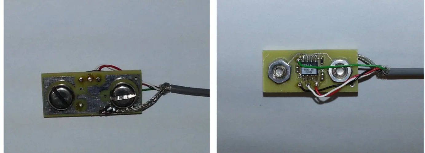
Each bipolar electrode-amplifier consisted of a pair of 8 mm diameter stainless steel electrode contacts separated by a distance of 10 mm (edge to edge), connected to an instrumentation amplifier (CMRR > 100 dB over the passband). A signal conditioner then bandlimited the signals between 15–1800 Hz, and provided selectable gain. Raw EMG were digitized at 4096 Hz with 16-bit resolution.
A single-finger restraint (Fig. 2.1) was custom-built with modular framing (10 Series Profiles, 80/20 Inc., Columbia City, IN, U.S.A.), and rigidly clamped to a table. The finger attachment was bolted to a force transducer (LC101-100 load cell; Omega Engineering, Inc., Stamford, CT, USA) to enable measurement of flexion and extension forces of one selected finger. A bridge amplifier/signal conditioner module (DMD465-WB; Omega Engineering, Inc., Stamford, CT, USA) was used to amplify and de-noised the load cell signal. The force channel was digitized at 4096 Hz with 16-bit resolution. A similar grip restraint (Clancy et al., 2006) was custom-built for simultaneous co-activation of three or four fingers, with net force measured by a single load cell.
Experimental procedures were approved by the New England IRB; all subjects provided written informed consent. The subject’s dominant forearm was cleaned with an alcohol wipe and conductive gel was applied. Then, 12 bipolar sEMG electrode-amplifiers were placed circumferentially, equidistant around the forearm, oriented parallel to the muscle fibers. The proximal edge of each bipolar electrode was mounted three fingers breadth from the antecubital fossa with a reference electrode attached over the head of the radius.
After donning a glove, the subject’s palm was arranged perpendicular to the table and then secured to the front of a restraint using Velcro, to stabilize the hand during contraction trials. Next, subjects were instructed to support their forearm on the cushioned elbow rest plate via contact at the olecranon process, with their arm extending along the sagittal plane. For finger trials, each finger was individually fixed to the restraint; while for grip trials, four fingers (thumb excluded) were simultaneously fixed to the restraint.
Subjects performed muscle contractions by interacting with a computer screen GUI. A vertical blue line displayed a computer-controlled target that guided the subject to complete different experimental tasks by exerting force on the load cell. A real-time feedback signal from the load cell was shown as a second red vertical line. Both lines were bounded within two fixed white vertical lines representing each subject’s 50% maximum voluntary contraction (MVC). The x-axis location of each feedback line (positive and negative) corresponded to extension-flexion forces, respectively.
2.2.2 Experimental Data Collection
Nineteen able-bodied human subjects (nine males, ten females; aged 23 to 62 years) each participated in one experiment. Subjects initially sat at the single-finger restraint and performed two 5-s 100% MVCs per finger, in each of flexion and extension, the average peaks of which were used as the subject’s MVCs. Next, they performed a 0% MVC (rest contraction) and separate flexion and extension 30% MVCs (for each finger) for 10 s each, utilizing force feedback on a computer screen.
Subjects then performed three dynamic target tracking contractions per finger, each 45 s in duration. The random target was a 1 Hz band-limited, white and uniform random process which moved randomly between ±(|30 %MVC Ext| + |30 %MVC Flx|)/2, with subjects tracking this movement by controlling the load cell force. A minimum two-minute rest interval was provided between contractions to limit fatigue.
After completing the single-finger trials, the subject was arranged into the grip restraint in a similar manner. In four-finger grip trials, all four fingers (thumb excluded) were secured to the apparatus. The same steps were followed to collect grip EMG and force data as were followed for single-finger efforts.
2.2.3 Analysis—Signal Processing
All signal processing was performed using MATLAB, with filtering applied in the forward, then reverse time directions, to achieve zero phase. To produce estimates of EMG standard deviation (EMGσ), the sampled EMG were highpass filtered (fc=15 Hz, 5th-order Butterworth) and 2nd-order IIR notch filtered (bandwidth 1 Hz) at the power line frequency and all harmonics (to attenuate power line interference). This filtering was followed by a first order demodulator (i.e., rectifier).
![Fig. 1.2. Skeletal Muscle Length-Tension Curves [Barrett et al., 2012]](https://thumb-us.123doks.com/thumbv2/123dok_us/1316912.2676032/17.918.279.628.131.461/fig-skeletal-muscle-length-tension-curves-barrett-al.webp)
![Fig. 1.4. Electrical activity of one individual motor unit [Marieb, 2008]](https://thumb-us.123doks.com/thumbv2/123dok_us/1316912.2676032/19.918.188.725.105.507/fig-electrical-activity-individual-motor-unit-marieb.webp)
![Fig. 1.5. Schematic representation of generation of a motor unit action potential (MUAP) from it constituent muscle fibers [Basmajian and DeLuca, 1985]](https://thumb-us.123doks.com/thumbv2/123dok_us/1316912.2676032/20.918.273.647.106.571/schematic-representation-generation-action-potential-constituent-basmajian-deluca.webp)