Error Estimation in Model-Driven Development for
Real-Time Software
∗†Oana Florescu, Jeroen Voeten, Jinfeng Huang, Henk Corporaal
Information and Communication Systems Group, Faculty of Electrical Engineering Eindhoven University of Technology
P.O. Box 513, 5600 MB Eindhoven, The Netherlands
Abstract
Model-driven approaches proved themselves not suited yet to support real-time software development. Even if they have the ability of capturing adequately both functional and non-functional (timing) characteristics of a system, they still lack an appropriate mechanism of generating an implementation from a model while preserving the properties verified. In previous work we have proven that, if the implementation trace is very close (-close) to a model trace, the properties verified in the model are preserved uptoin the system realiza-tion. This deviation is due to the model assumption of zero-time for computational actions that, in reality, no target platform can ensure. This paper proposes an approach for esti-mating the time-deviation between model and implementation, by modeling the realization of the system when software components would run on the target platform. The approach is based on Software/Hardware Engineering method for complex real-time systems design and the Y-chart scheme concepts.
1
Introduction
The main purpose of models is to help engineers understand the interesting aspects of a system, before getting to the expense and trouble of actually building it. While traditional forms of engineering have a well-developed modeling methodology and their use of models is generally recognized as a useful and effective technique, software engineering, and particularly real-time embedded software, is still a rather emerging discipline. It is applied to increasingly complex systems and its modeling techniques are neither mature nor reliable yet. Nevertheless, software models have a unique and remarkable advantage over the other engineering models: they can be used to automatically generate executable programs for particular platforms. Starting with a simplified and highly abstract model, refinements can be carried on until a complete specification is obtained, including all the details necessary in the final product, and from which adequate computer tools can generate an implementation. The initiative of the Object Management Group (OMG) for Model-Driven Architecture (MDA) [Gro01] shows that interest in technologies for supporting model-driven development has increased.
Nowadays, embedded systems, found in cars, airplanes, medical devices, employ real-time software components to synchronize and coordinate different processes and activities. Their behavior must meet hard timing constraints, either for people’s safety or simply to make things
∗
This work is being carried out as part of the Boderc project under the responsibility of the Embedded Systems Institute. This project is partially supported by the Netherlands Ministry of Economic Affairs under the Senter TS program.
†
This research is supported by PROGRESS, the embedded systems research program of the Dutch organization for Scientific Research NWO, the Dutch Ministry of Economic Affairs, the Technology Foundation STW and the Netherlands Organization for Applied Scientific Research TNO.
work correctly. The correctness of a hard real-time software component, that works together with other software and hardware components to achieve the specified behavior, depends not only on the logical result obtained but also on the moment in time the result was computed. Experience showed that model-driven development for these software systems is not suited to cope with real-time system design. Traditional design approaches proved themselves unable to predict both functional and timing behavior of a system from its model. The main cause of this is their inability of capturing adequately both functional and non-functional (timing) characteristics while abstracting from low-level details [HVVvB03]. The usual approach focuses first on the logic of the application while timing concerns are postponed until the logic is satisfactorily designed [SM03].
A real-time application model must cover the system’s required features, such as timeliness, architectural structure, concurrency and communication, and allows iterative refinements to-wards a complete specification. Mathematical definition of the modeling language semantics provides the means to reason properly about system’s properties and to predict its behavior. Even if adequate real-time software models can be built, yet there is another issue: how to get automatically from a model to its implementation in such way that the generated code behaves exactly as the model, without unwanted side-effects. So, an appropriate design methodology should provide both an expressive and well-founded modeling language as well as a transforma-tion mechanism for automatic and property-preserving code generatransforma-tion.
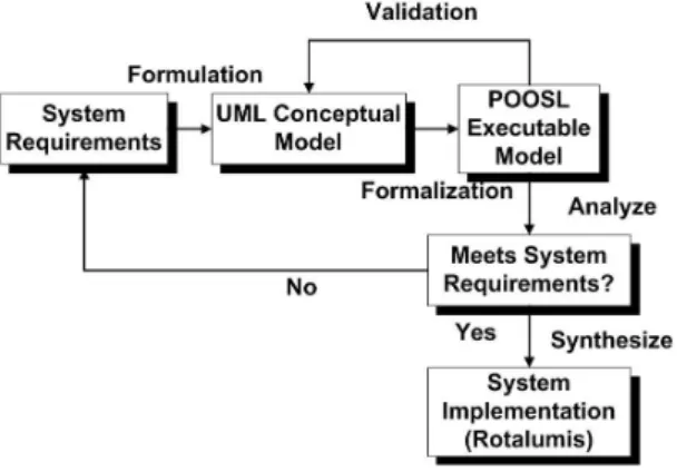
Software/Hardware Engineering (SHE) method [vdPV97] is a system-level design methodol-ogy (Figure 1), which meets both above-mentioned requirements. SHE is based on a formally de-fined modeling language, Parallel Object-Oriented Specification Language (POOSL) [vdPV97], for building software models, and on a code generation tool, Rotalumis [vB02], for generating software implementations. The preservation of properties from model to implementation is guar-anteed by the-hypothesis [HVG03]. This hypothesis is satisfied if every execution trace of the implementation is-close to a trace in the model, with respect to time.
Figure 1: SHE method for real-time systems design
A model represents an approximation of a system realization, as it removes or hides irrelevant details, allowing designers to focus more easily on the essentials with the purpose of analyzing the system properties. However, due to all the approximations made in a model, the real-time properties verified cannot hold precisely in the software implementation: a ”deviation” appears between model time and physical time, accordingly between model and implementation. This is primarily due to the fact that actions in the model are timeless, while in reality, no matter how fast a processor is, it will always take a small amount of time to execute them. Secondly, in a model, a number of events may happen at the same moment, while in the implementation they will occur within a small time interval. However, the code generation tool is able to generate an implementation whose execution trace is very close (-close) to a trace in the model, with respect to time. So although the execution trace of the implementation may not be in the model itself,
there exists a trace in the model that is -close to it. Since the analysis can take into account all possible execution traces of a model, we are also able to reason about all possible traces in the implementation. Provided that -hypothesis is satisfied, all the properties of the model are preserved uptoin the implementation [HVG03].
It is important to know the size of the time-deviation () between a model and its imple-mentation, since it indicates what properties are satisfied by the implementation. One way for getting the value ofis by direct measurements. The software implementation is generated and run on the target platform, from which designers can get information about the error introduced by the mapping. If the error is found too large, they can decide on whether to refine the model by changing the algorithm to handle the problem or to replace the target platform by another one of better performance.
This paper proposes a better approach, that saves the trouble of generating the code, run-ning it and measuring the error for each target platform. Combirun-ning the idea of model-driven development with the design space exploration techniques facilitated by the Y-chart scheme, we can model ”the realization” of a system, namely we can model the mapping of the software implementation on the target platform. Based on the formal semantics of the POOSL modeling language, we can make an estimation of the error, speeding up the process of finding a suitable platform for the real-time system.
The paper is organized as follows. Section 2 reviews the current approaches for modeling and design of real-time systems. Section 3 discusses the mechanisms of preserving the properties of a model in the realization as well, whereas Section 4 presents the Y-chart scheme concepts on which we are relying in our approach. The combination of the above-mentioned mechanisms with the Y-chart concepts is presented in Section 5 and Section 6 demonstrates the applicability of the proposed approach in a case study. Conclusions and future work are given in Section 7.
2
Related Work
The Object Management Group (OMG) has adopted the Unified Modeling Language (UML) [Gro03] as a standard facility for constructing models of object-oriented software. UML has proven to be suitable to model qualitative aspects of a system and there were extensions defined to it to provide a standardized way of denoting timing aspects for real-time systems [SM03]. Nevertheless, application of mathematical analysis techniques remains complicated due to the difficulty of relating formal techniques to UML diagrams. Although UML is largely used both in industry and academia, it has shown not to be very appropriate for modeling hard real-time systems as it lacks a formal semantics, restraining it from a proper analysis of system behavior. Based on UML, a couple of design approaches, that support model-driven development for real-time systems, were conceived. However not all of them satisfies all the characteristics of hard real-time design, namely to have both a well-founded and expressive modeling language as well as an automatic and correctness-preserving transformation technique.
Real-Time Object-Oriented Modeling (ROOM) method [SGW94], based on UML, showed itself not suitable for modeling real-time systems due to ROOM’s platform-dependent semantics: the results of a model simulation are dependent on the target hardware. ROOM relies on an asynchronous timing mechanism that refers to the physical clock and consequently, accurate analysis and prediction of timing behavior of a system cannot be made [HVVvB03]. Regarding the automatic code generation, the implementation of a software component is obtained by linking the model to a service library, which actually acts like a virtual machine on top of the target platform. The implementation is in fact an executable model, so it inherits all the problems related to the platform-dependent semantics encountered in the model. Besides the lack of a proper model analysis, the properties specified in the model cannot be satisfied by the implementation.
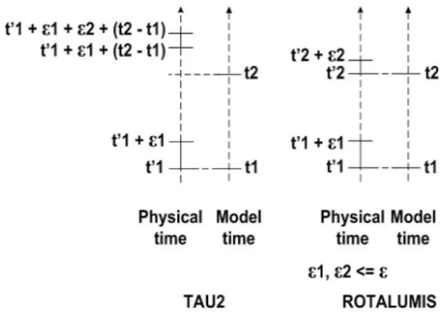
Another UML-related design approach, TAU2 [Tel] relies on the concept of virtual time whose progress is not directly affected by the progress of the physical time. In this way, real-time behavior of models is well-defined in a platform-independent way. Although TAU2 can provide a reliable way of analyzing a model it does not have a reliable transformation mechanism to guarantee preservation of model-verified properties in the implementation. During automatic code generation, model time is replaced by physical time and all expressions referring to some amount of time will refer to at least that amount of time. As timing errors are accumulated during the execution, the issuing moment of different actions can deviate from those observed in the model and also the ordering of the events can change, so model and implementation are not consistent [HVVvB03].
Figure 2: Relation between model time and physical time
To support the design and development of real-time systems, Software/Hardware Engineer-ing (SHE) method [vdPV97] provides a well-founded and expressive language, Parallel Object-Oriented Specification Language (POOSL) [vdPV97], for modeling and analysis of complex real-time systems, and a correctness-preserving transformation tool (Rotalumis [vB02]) for au-tomatic code generation. SHE method uses a UML profile to formulate the concepts for realizing the requested functionality of a system. The requirements are formulated as questions, which actually determine the design issues that need to be addressed [TvdPV03]. The result is an infor-mal description of system’s concepts and requirements that is not executable. The UML profile smoothes the application of POOSL for developing an executable model (Figure 1). POOSL ac-tually formalizes the behavior specified in informal UML diagrams, establishing a formal unifying model. The language’s mathematically defined semantics guarantees an unambiguous interpre-tation of a model, independent on the underlying platform and [HVG03] proves the ability of Rotalumis to preserve the properties of the system when the software implementation is gen-erated. Property-preservation is achieved by the synchronization of model time with physical time: all the actions are executed as close as possible to the moment that in the model they would have been executed (Figure 2). There will always be a time-deviation between a model specified in POOSL and its implementation generated by Rotalumis and this paper proposes an approach for the estimation of this deviation.
3
Property-Preservation Mechanism
Model-driven approaches are based on the idea of taking a design model and building a complete system implementation from it. Preferably this action should be largely automated, saving a lot of costs and time. Moreover, the transformation should guarantee that the properties verified in the model will be satisfied by the implementation as well. An automated tool would eliminate the errors caused by hand-writing software and, on the other hand, the realization of the system
would behave the same as the model that was already analyzed and validated.
In this section we will explain the formal mechanism to automatically translate a POOSL model into a software implementation, while preserving the properties.
POOSL modeling language is equipped with a complete mathematical semantics, that can formally describe concurrency, distribution, communication, timing and functional features of a system in a single executable model, using a small set of very powerful primitives. Primitives can be combined in an unrestricted fashion and any combination has a precisely defined meaning. The formal semantics guarantees an unambiguous interpretation of a POOSL model, guided by semantical axioms and rules.
POOSL consists of a process part and a data part. The process part (processes and clusters) is based on a real-time extension of the process algebra CCS [Mil89] and is used for specification of real-time behavior of active components. The data part is based upon traditional concepts of sequential object-oriented programming and is used to specify the information that is generated, exchanged, interpreted or modified by the active components.
The semantics of the language is based on a two-phase execution model: the state of a system changes either by asynchronously executing atomic actions, such as communication or data computation, without time passing (phase 1), or by letting time pass synchronously without any action being performed (phase 2).
To obtain an executable model from a POOSL specification, all primitives must be mapped to the constructs of a target language, like C++, Java, or Smalltalk. As there is a large difference of expressivity between POOSL and any of these languages, the behavior expressed by a single POOSL primitive might not be captured by a single target language construction. An additional problem may be that in some languages there are restrictions regarding the composition of different constructs, while in POOSL all primitives can be used in any combination.
To cover the expressivity gap between a realistic system level design language (POOSL) and an imperative programming language (C++), without relying on a real-time operating system, execution trees were developed [vBVG99], [vB02]. Each process in a POOSL model is represented by a C++ data structure named process execution tree (PET) and each node of such a tree represents a statement in the specification of behavior. The behavior of a node is based upon the inference rules underlying the formal semantics of the language. Only the leaves of a process execution tree can generate requests to perform certain actions, such as data communication, statements, delays, which are sent to a scheduler. The scheduler uses action urgency to grant all executable action requests before (model) time advances. According to the granted actions, the trees adapt themselves to reflect their new state. The correctness of this execution method, with respect to the language primitives semantics, has been proven in [Gei02].
The mapping of POOSL constructs into C++ constructs using process execution trees en-ables designers to generate an executable model, capable of performing every possible transition based on the specification. At this point the question that arises is how to relate the time in the executable model to the physical time. Although processes described in a POOSL model need no model time to pass for any action, except for delays, their actual execution on a processor takes a small amount of time, no matter how fast that processor is. Therefore, even though the analysis of a model does not take into account the execution time needed by the actions specified in the model, the realization of the model has to deal with that. Consequently, in order to have a software implementation consistent with the model, the model time should be synchronized with the physical time.
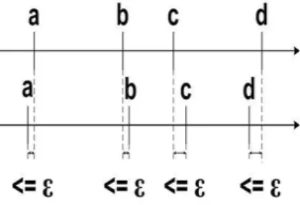
A state sequence with a time interval attached to every state is called a timed execution trace [HVG03]. Two timed execution traces are -close if they have exactly the same sequence of states and the least upper bound of the absolute time differences between left-end points of corresponding intervals is less than or equal to(Figure 3). The-hypothesis [HVG03] assumes that every timed execution trace in the implementation is -close to a timed execution trace in
the model. In case this hypothesis is satisfied, then the implementation meets all -weakened properties verified in the model. To ensure the -hypothesis, the scheduler tries to keep the execution trace as close as possible to a trace in the model with regard to the distance between timed state sequences (Figure 2). To synchronize model time with physical time, all the actions that in model happen at a certain moment t are scheduled to be executed in physical time in an interval of length around that moment t. Due to platform characteristics, the scheduler might not be able to satisfy the-hypothesis. In this case, designers can decide whether to refine the model so that it can handle the time-deviation or choose a better platform with respect to performance.
Figure 3: Two finite timed state sequences -close
4
Y-chart Concepts
Y-chart scheme is used for design-space exploration. A distinction is made between applications (that describe the functional behavior of a system) and architectures (that eventually should execute the functional behavior). This allows exploration of different application-architecture combinations.
A functional model is usually specified in terms of a collection of communicating tasks and a resource model is specified as a collection of (parameterized) computation, communi-cation and/or storage resources that are capable of executing the desired functional behavior [vWVtB03]. With parameterized resource entities it is easier to check different architecture combinations.
Usually, the separation of system desired behavior from the description of the architecture underlying this behavior implies that timing behavior comes into sight only when the mapping is done. By that moment, the application model describes how the system should behave and the architecture model specifies what it is able to process and under what restrictions (regarding time, storage amount, communication). Tasks specify the desired behavior in terms of task-level instructions, while resources have to process tasks requests in order to accomplish this behavior. Mapping an application on a hardware architecture means to map each entity in the functional model onto a resource entity in the resource model. At the task level, the amount of time needed for processing is not known until the mapping stage, because this information is comprised in the description of resource entities. An accurate analysis regarding timing behavior of the system can only be made after the mapping is done, as the model time elapses only in resources. We can say that the application model (functional behavior) is influenced by the architecture model whose presence is mandatory in order to make reasonable predictions about non-functional system properties. By considering only the model of the application, one cannot reason properly about timing aspects, which is indispensable for real-time systems.
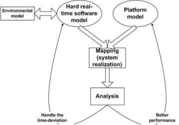
For modeling and analysis of hard real-time systems, we propose a different approach, also based on the Y-chart scheme (Figure 4). As already shown in previous sections, when model-ing hard real-time software systems it is very important to capture both functional and timmodel-ing
Figure 4: Y-chart scheme for hard real-time systems
requirements in order to make a proper analysis and to automatically generate a software im-plementation that is consistent with the model. Therefore, in the application model the timing behavior is comprised as well, so that it is possible to analyze the timing behavior of the system from the application model, without involving the underlying architecture. Besides the model of the application, it is also required to model the physical devices that are controlled by the software and that exhibit a desired behavior [But97]. Only the software components will be mapped on the architecture model, but the model of the controlled physical devices is needed for reasoning about the system behavior as a whole. The hardware platform, on which the software will run, is required to support the execution of the application to achieve both func-tionality and timing behavior specified in the model. The mapping of the application on the hardware platform represents the assignment of each software component to a computational resource that mimics the execution of its requests by time delays. The main difference from previous approaches based on the Y-chart scheme is that this mapping does not influence the behavior of the software model: the platform is notified by the software components about the actions they have done and that in the real systemit should perform. We call this mapping a model of a realization because it gives a picture of how the system in reality would run on a particular platform configuration. Different mappings on different architectures can be analyzed in order to find the most suitable one. The suitability of a mapping is analyzed in terms of the size of the error () introduced. Theindicates to what extent the architecture can satisfy the timing requirements of the system.
5
Model the System Realization Using Y-chart
In the previous section, we have shown how we can model the realization of a hard real-time sys-tem using the Y-chart scheme. On one hand, we have the model of the software application that controls different physical devices and, on the other hand, the model of the underlying platform (Figure 4). In order to analyze the behavior of the system when the software components will actually run on the target platform, we reach the mapping stage of the Y-chart scheme. Oppo-site to traditional approaches, we do not modify the application model. Our approach, based on SHE method for design of real-time systems, realizes a feasibility check to see if a particular architecture can meet the timing requirements specified in the model, without interfering with the behavior of the system.
A real-time system model is described in terms of communicating tasks (modelled as POOSL clusters or processes), some representing software components and others being discrete-event approximations of continuous-time environmental components. Software components can
com-municate with each other according to their functionality needs and they can also comcom-municate with environmental components that they should control in reality. A platform (also modelled as a POOSL cluster) is described in terms of execution times for all task-level instructions, that are required to be executed on that architecture, and the behavior of a scheduler that runs on that platform and that schedules the arrived requests. Given the features of POOSL modeling language, the mapping consists in creating a communication channel between every software component in the system model and the architecture. Every time when an action is performed in a software component, the corresponding process sends a message through the communica-tion channel to the architecture to inform what it has done. The behavior of the system is not changed because the messages sent act as notifications for the platform to know what it has to handle and to analyze whether it is able to meet the -hypothesis or not. Sending a message takes no model time and hence the analysis of the real-time system properties is not influenced. The architecture model is willing to receive notification messages at any moment and it mimics the execution of actions by letting time pass according to the amount of execution time needed in reality to perform that action.
As presented in a previous section, there is a time-deviation between a model and its realiza-tion due to model assumprealiza-tion of zero-time for every acrealiza-tion in a POOSL model. According to the
-hypothesis, to keep the properties verified in the model in the realization as well, a synchro-nization of model time with physical time is needed. A scheduler, which is implemented in the model of the platform, tries to schedule all the actions that arrived for execution at momenttin a time interval aroundt. The least upper bound of the amount of time needed for the execution of all the actions notified to the architecture at momenttis considered the time-deviation of the implementation from the model.
The execution time of different actions is known beforehand as the worst case execution time that the platform can give [LM99]. Estimating the time-deviation of the implementation from the model is very important as it allows designers to choose whether to change the target platform or to refine the model. They can analyze the realization of the system on a different underlying platform or modify the model so that it can handle the problem (Figure 4). This might mean that, for example, some computations are performed earlier, according to the value estimated for the error, so that the result can be delivered in time in the realization of the system.
6
A Hard Real-Time System Example: A Train Crossing
Sys-tem
A train crossing system (Figure 5) has been chosen as an example of a hard real-time control application, on which we emphasize our approach to estimate the time-deviation of the realiza-tion from the model and how it can be dealt with. A scenario of the operarealiza-tion of this system is presented in [HVvdP04] and more details about the system design can be found there. In this paper we will focus mainly on presenting the relevant aspects regarding the model of the system’s realization.
The system consists of four train stations connected by perpendicular tracks on which two trains are running. The purpose of modeling this system is to analyze how we can built it in such way that the trains never collide and each train spends as little time as possible on its way from one station to the other. The crossing area acts as a shared resource between the trains and there are no sensors placed in this region to detect if a train is coming. Each of the four stations has a sensor in its immediate neighborhood and the moment when a train arrives near the crossing area is computed based on the train speed and the distance that it should have travelled from the last sensor it passed by. To compute this distance the speeds of trains are assumed constant.
Figure 5: The train crossing system
In the model, the designer establishes the size of a critical zone, which represents the safety distance from the crossing from which a train has to check whether it can pass or not. If the crossing is not free, the train must stop and wait until the other one has left the crossing area. The bigger the size of the critical zone is, the longer a train has to wait for the other train to pass. The critical zone should be as small as possible to allow a train to stop just before the crossing area, letting the other train pass and still avoiding the trains collision. If the time-deviation between implementation and model is large, it might be the case that a collision cannot be avoided. A train may stopwithin the crossing area due to the fact that the processor cannot make sure that the checking of the crossing is done fast enough. A processor of better performance might execute all the actions asked for at a momenttin less time, so the error will be less than in the previous realization and the collision can be avoided because the train stops in time.
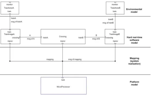
Figure 6: The model of the system realization
In the system model, the crossing and the trains are represented as parallel POOSL pro-cesses (Figure 6). For each train in the system there is a train controller (TrainImageA and
TrainImageB) that communicates with the crossing (Crossing) to ask for access permission. A train controller also exchanges messages with its corresponding train actor (TrainActorA or
TrainActorB) to order it to stop or to get information about its position. A train actor is a discrete-event model of a continuous-time component, so it represents a part of the controlled environment. Only the train controllers and the crossing are software components and will be mapped on the target platform. The POOSL processes corresponding to the train actors will not be.
The target platform model, depicted in Figure 7, receives notification messages from the three software components in the system model (the two train controllers and the crossing) about what actions they have done and that would be performed by a processor in the real system. As the system only has a small number of software components, we have chosen to implement it on a single-processor platform. A queue (ReqQueue) is modelled to always be ready for receiving new messages from the software components model, while the messages already stored are forwarded one by one, in the ordering of their arrival, to be executed by a scheduler (Scheduler). The scheduler mimics the execution of each modelled action by letting time pass, in accordance with the amount of time needed in the real execution, and then offers itself ready for another request.
Figure 7: The model of the target platform
In our approach, we are relying on the two-phase execution of a POOSL model, namely that model time passes only when no other action can be performed. For this reason, the modelled ”execution” of all the actions that happened at model timet does not start before they all have been notified to the platform. The least upper bound of the amount of time needed for the execution of all the actions notified at moment t represents the time-deviation of the software implementation from its model.
For the target platform, we have modelled a processor that needs 1µs for each action re-quired from a software component in our system. An important remark is that the processor is modelled to execute only the actions of the software components in the train crossing system. Analyzing the model of the realization, we have obtained that the time-deviation between the software model and its implementation on this processor would be 6µs. The delays due to the communication with the environment are already taken care of in the environmental model con-sisting of theTrainActors (the upper bound of the CommunicationDelayis 0.02s). To compute the size of the critical zone we also need some numerical details about the system. The length of the crossing area is 0.044m. The speed of the trains is assumed to be constant between two sensors if there is no stop. Train aruns with 0.470m/s and trainb with 0.250m/s. They need 0.045m, respectively 0.015m for deceleration before standing still.
If the error between model and implementation would be zero, then the size of the critical zone could be:
CriticalZone=CrossingLength/2 +T rainADecelerationLength+ +T rainASpeed∗CommunicationDelay= 0.06794m.
CriticalZone=CrossingLength/2 +T rainADecelerationLength+ +(CommunicationDelay+)∗T rainASpeed= 0.06794282m.
We have computed the size of the critical zone considering the speed of train A because it is faster than train B. As it can be seen from the result obtained, is very small and practically has no influence. This means that the model can also be implemented and run on a platform of lower performance. In this case can be larger and consequently refinements must be made to the system model so that it can handle the time-deviation and make sure that the trains do not collide [HVvdP04].
For safety critical systems, such as this simple example, it is crucial to eliminate all the possibilities of system’s failure. The estimation of system realization deviation from the model saves the designer from the trouble of building the actual system and exhaustively testing it on different platforms to check its functional and timing correctness.
7
Conclusions and Future Challenges
In this paper, we have proposed an approach for estimating the error that appears in model-driven real-time software development. The approach is based on SHE method for real-time systems design and the Y-chart scheme concepts.
It is important to know the time-deviation () that exists between a model and its imple-mentation in order to reason about to what extent the properties verified in the model can be preserved in the implementation. This time-deviation can never be zero, but it can be decreased using a processor of better performance or compensated by a suitable system design that can bear with the error. If a suitable platform is not found, the model of the real-time application can be modified such that it takes into account the time-deviation and the resulting implementation will behave properly from safety critical reasons point of view.
The benefit of the approach presented in this paper consists in the fact that the designer is able to predict from the model what properties can be preserved and to what extent. He can also reason about possible refinements of the model to compensate the time-deviation. The approach is suitable for control-dominated applications, in which actions typically take a short amount of time, so the time-deviation usually obtained is rather small. In data-dominated applications, computations take a considerable amount of time, therefore the value ofis larger. Hence future research is required to make the approach applicable to this kind of applications as well.
Another benefit of this approach is that of saving the trouble of iterating a couple of times through the generation of the real-time system’s implementation and measuring the feasibility of each processor architecture. It also provides the means for design space exploration by easily modifying the architecture model. A processor architecture is described in terms of values for different actions’ execution times. In order to model a different processor architecture, it suffices to replace the old values with those of the new processor, so the design itself is neither removed nor replaced: the designer needs only to place the right values for the execution times of actions. A major future challenge of this research is triggered by complex real-time systems that require heterogeneous distributed architectures to run on. Distribution of processes in the design over multiple processors, while still satisfying the hard timing constraints of the system, is still an unsolved issue.
References
[But97] Giorgio C. Buttazzo. Hard Real-Time Computing Systems: Predictable Scheduling Algorithms and Applications. Kluwer Academic Publishers, Boston MA, 1997.
[Gei02] Marc G.W. Geilen. Formal Techniques for Verification of Complex Real-Time Sys-tems. PhD thesis, Eindhoven University of Technology, Eindhoven NL, 2002. [Gro01] Object Management Group. Model Driven Architecture (MDA). OMG document
ormsc/2001-07-01, Needham MA, 2001.
[Gro03] Object Management Group. Unified Modeling Language (UML) - Version 1.5. OMG document formal/2003-03-01, Needham MA, 2003.
[HVG03] Jinfeng Huang, Jeroen P.M. Voeten, and Marc C.W. Geilen. Real-time property preservation in approximations of timed systems. InProceedings of the First ACM & IEEE International Conference on Formal Methods and Models for Codesign (MEMOCODE’2003), June 2003.
[HVvdP04] Jinfeng Huang, Jeroen P.M. Voeten, and Piet van der Putten. Predictability in real-time system development: (2) a case study. In Proceedings of the Forum on Specification & Design Languages 2004 (FDL’04), September 2004.
[HVVvB03] Jinfeng Huang, Jeroen P.M. Voeten, Andre Ventevogel, and Leo J. van Bokhoven. Platform-independent design for embedded real-time systems. InProceedings of the Forum on Specification & Design Languages 2003 (FDL’03), September 2003. [LM99] Yau-Tsun Steven Li and Sharad Malik. Performance Analysis of Real-Time
Em-bedded Software. Kluwer Academic Publishers, Boston USA, 1999.
[Mil89] Robin Milner. Communication and Concurrency. Prentice Hall, Englewood Cliffs NJ, 1989.
[SGW94] Bran Selic, Garth Gullekson, and Paul T. Ward. Real-Time Object-Oriented Mod-eling. John Wiley & Sons, Inc., New York NY, 1994.
[SM03] Bran Selic and Leo Motus. Using models in real-time software design.IEEE Control Systems Magazine, 23(3):31–42, June 2003.
[Tel] Telelogic. TAU generation 2. http://www.tau2g.com.
[TvdPV03] Bart D. Theelen, Piet H.A. van der Putten, and Jeroen P.M. Voeten. Using the SHE method for UML-based performance modeling. In System Specification & Design Languages (Best of FDL’02), chapter 12, pages 143–160. Kluwer Academic Publishers, Dordrecht NL, 2003.
[vB02] Leo J. van Bokhoven. Constructive Tool Design for Formal Languages: From Se-mantics to Executing Models. PhD thesis, Eindhoven University of Technology, Eindhoven NL, 2002.
[vBVG99] Leo J. van Bokhoven, Jeroen P.M. Voeten, and Marc C.W. Geilen. Software syn-thesis for system level design using process execution trees. InProceedings of 25th Euromicro Conference, pages 463–467, 1999.
[vdPV97] Piet H.A. van der Putten and Jeroen P.M. Voeten. Specification of Reactive Hard-ware/Software Systems. PhD thesis, Eindhoven University of Technology, Eind-hoven NL, 1997.
[vWVtB03] Frank N. van Wijk, Jeroen P.M. Voeten, and A.J.W.M. ten Berg. An abstract modeling approach towards system-level design-space exploration. InSystem Spec-ification & Design Languages (Best of FDL’02), chapter 22, pages 267–282. Kluwer Academic Publishers, Dordrecht NL, 2003.