European Association for the
Development of Renewable Energies, Environment and Power Quality (EA4EPQ)
International Conference on Renewable Energies and Power Quality (ICREPQ’12)
Santiago de Compostela (Spain), 28th to 30th March, 2012
Experimental DTC of an Induction Motor Applied to Optimize a Tracking System
B. Mokhtari1, A. Ameur1, M. F. Benkhoris2, L. Mokrani1 and B. Azoui3
1LEDMaSeD Laboratory, Electrical Engineering Department, Laghouat University, BP 37G, Ghardaia Street, Laghouat (03000), Algeria, E-mail: [email protected], [email protected], [email protected]
2IREENA, Polytech'Nantes, Site de Saint-Nazaire, 37 bd de l'Université - BP 406, 44602 Saint-Nazaire cedex E-mail: [email protected]
3LEB Laboratory, Electrical Engineering Department, Batna University, Chahid M.E.H. Boukhlouf Street, Batna (05000), Algeria, E-mail: [email protected]
Abstract.
In recent years, the areas of industrial application of high performance AC drives, especially the induction motor (IM), based on Direct Torque Controller (DTC) technique has gradually increased due to its advantages over the other techniques of control. Among these applications are cited, propulsion and tracking systems. This work presents the experimental part of a research project conducted by the authors where they have implemented an algorithm for a DTC in order to achieve a tracking system designed for a series of solar panels to maximize its overall efficiency. In this paper, three different switching tables are presented for choosing the best between them for a less fluctuation in torque. This study is justified by reduced cost of implementation compared to other methods that require the use of expensive hardware and complicated control techniques. The tests were carried out under the same conditions with the same equipment of the testbed, to get a good comparative study. Three variants were tested: simple switching table, table of sectors shifted by 30 ° and a table with 12 sectors. The results show an improvement, but a dilemma between the torque ripple and those of the stator flux.Key words
Induction Motor, Direct Torque Control, Switching Table, Torque and Flux Ripples, Tracking system, solar panel efficiency.
1.
Introduction
High dynamic performance of servo motor drives is indispensable in many applications of today’s automatically controlled machines. AC servo motor control has attracted much attention recently in the power electronics field [1].
The IM has several advantages over other types of electric motors. The recent development of the technology of power electronics has put in competition a few other types of motors, which had difficulty of design in the past, such as the permanent magnet synchronous motor, for example. But probably, it will stay, for next years, the most dominant motor in industrial applications, because of its techno-economic characteristics [1-6].
DTC was introduced in 1985 by Takahashi and Depenbrock especially for the asynchronous and synchronous machines [1], [6]. The main advantages of DTC are the simplicity of the control scheme and its unresponsiveness to parameters variations (except stator resistor), [7].
In the conventional DTC, the employment of the hysteresis controllers, in order to regulate the stator magnetic flux and torque, have by nature high torque ripples and variable switching frequency depending on speed, load torque and hysteresis bands. This leads to a difficulty to control torque and flux at a very low speed [1-8].
Lascu, C.et al.in [9], have presented a modified DTC using (SVM) for an IM with fixed switching frequency and low ripple for torque and flux. This system requires two proportional-integral (PI) controllers properly tuned at the same time for the best performance.
Martins, C. et al in [10] and Cirrincione, M., et al. in [11] have proposed solutions to reduce the torque ripples, this strategy relies on increasing the number of vectors applied voltage, which can improve the ripples band of torque.
The IM which is powered by a three-level inverter has the same dynamic performance as those obtained with a two-level inverter with low torque and flux ripples, but this increases the cost of implantation, due to the cost of the three-level inverter and also the switching table becomes large.
The aim of this study is to have a simple and less expensive system, to apply it to a tracking system which was proposed by [5], and can be used for thermal system or photovoltaic; this requires that it focuses on improvements, software side only.
For this, we must keep the same equipment of testbed and the same control conditions (gains of PI regulator, reference values, hysteresis comparators), and therefore, only the switching table must be changed.
considered to be insufficient and we have to make them more efficient to supply a more significant energy for low and medium power systems.
Among several parameters that influence performance we may cite the irradiation of sunlight projected onto the solar panel and captured by photovoltaic cells. Several studies have been made to improve the overall efficiency and thus benefit the most from the obtained transformed energy [12-15].
The sunlight capture block proposed by the authors in [5], is updated and corrected so that it is ready to achieve soon. Figure 1 shows a diagram of the new structure. It differs from the previous model by the position of the photodiode which is responsible for the detection of the sunrise, because it is more convenient. So we must place it in the back of the solar panel so that it is directly in front of sunrise.
The east way of sun rays
Shadow
The side of solar panel
Tube sized according to the performance degradation
Two photodiodes Sunrise photodiode
Panel surface
Rotation axis
Fig. 1. A new structure of the sunlight capture block
The experimental study examines a DTC applied to an IM for three different switching tables: simple switching table, table with sectors shifted by 30° and table with 12 sectors in order to reduce the ripples of the electromagnetic torque and flux.
2.
Optimal position captor
This block is designed by three photodiodes, two are located on the front of the solar panel, their role is to ensure the optimal location of the sun during the day, while the third photodiode located in the back of the solar panel to detect sunrise when the panel is facing west. One of the two photodiodes included in a tube of predetermined length (depending on the desired accuracy of degradation of the sunlight) to detect the shadow when the sun moves along its trajectory. The system will be locked when we reach the two logic states: '100 'and '001', where '1 'represents an excitation of the photodiode and '0' represents the absence of excitation.
The following table lists all possible states that can occur during the whole day of operation.
Table 1. Summary of the system proposed during the day
Event (logical) State Action (control)
Sunrise 100 Rotate to the East Ray ┴ Panel 011 Lock (no rotation) The Sun Moves 001 Rotate to the West Ray ┴ Panel 011 Lock (no rotation) Clouds / Sunset 000 Lock (no rotation)
-Clouds missing 001 Rotate to the West
-Sunrise 100 Rotate to the East
If we symbolize (left to right) the state of the first photodiode with 'A', and that of the second with 'B' and then we use 'C' for the third, we can see from the table 1, that the movement will begin in two ways:'100 ' and '001'.
3.
IM model
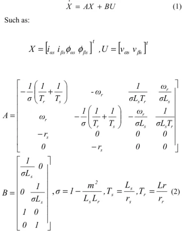
The stator and rotor flux equations of IM can be written in the reference frame of Park in the following form:
BU AX X• = + (1) Such as:
[
i
i
]
,
U
[
v
v
]
X
=
αs βsφ
αsφ
βs t=
αs βs t ⎥ ⎥ ⎥ ⎥ ⎥ ⎥ ⎥ ⎦ ⎤ ⎢ ⎢ ⎢ ⎢ ⎢ ⎢ ⎢ ⎣ ⎡ − − − ⎟⎟ ⎠ ⎞ ⎜⎜ ⎝ ⎛ + − ⎟⎟ ⎠ ⎞ ⎜⎜ ⎝ ⎛ + − = 0 0 r 0 0 0 0 r T σL 1 σL ω T 1 T 1 σ 1 ω σL ω T σL 1 ω -T 1 T 1 σ 1 A s s r s s r s r r s r r s r s r⎥
⎥
⎥
⎥
⎥
⎥
⎥
⎦
⎤
⎢
⎢
⎢
⎢
⎢
⎢
⎢
⎣
⎡
=
1
0
0
1
σ
L
1
0
0
σ
L
1
B
s s,
r r s s s r s 2r
Lr
T
,
r
L
T
,
L
L
m
1
σ
=
−
=
=
(2)
In addition, the electromagnetic torque can be expressed by:
)
i
-i
p(
2
3
T
e=
φ
αs βsφ
βs αs (3)The mechanical equation of the IM can be expressed as flows:
Ω
f
T
T
.
Ω
J
=
e−
r−
r(4)
4.
Conventional DTC
The DTC, as shown in figure 2, consists of directly controlling the inverter switches turn OFF or ON, on the calculated values of the stator flux and torque from relations (6) and (7).
The reference frame related to the stator, makes possible to estimate flux and torque on the one hand and the position of flux stator on the other hand.
The aim of the switches control is to give the vector representing the stator flux the direction determined by the reference value.
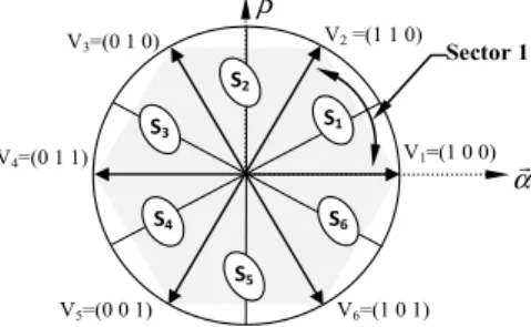
The synthetic sequence can be illustrated through the following example: Assuming that the flux vector is located in sector 1 [5], then if the error between the reference flux and the stator flux is positive, we must increase the flux, this is only possible by applying a voltage vector in the same direction, according to (4) or V1 (100), V2 (110) or V6 (101).
However, applying voltages of opposite direction V3 (010), V4 (011) or V5 (001) decreases the variation of the flux. On the other hand, if the error between the reference torque and the electromagnetic torque is positive we must increase the electromagnetic torque by applying the voltage vectors in the half plane of positive angles, according to (5), i.e. V2 (110), V3 (010) or V4 (011). Trying vectors V1 (100), V5 (001) or V6 (101), decreases the torque [5].
)
(
)
(
0 0⎪
⎪
⎩
⎪⎪
⎨
⎧
−
=
−
=
∫
∫
t s s s s t s s s sdt
I
r
v
dt
I
r
v
β β β α α αφ
φ
(5) (6) ) ( ) 1 (k s k VsTE s VsTE s + ≈φ + →∆φ ≈ φ ( sin( ) (7) ' ') k k Te = φs+φr = φs φr δ where: TEis the sample timeFig.2. Block Diagram of a Conventional DTC
A two levels classical inverter can achieve seven separate positions in the phase corresponding to the eight sequences of the voltage inverter [1], [5]. Table 2 shows the sequences for each position. Furthermore, Tables 4 and 5 have the sequences corresponding to the position of the stator flux vector in different sectors for the others strategies of ST (see figures 3 and 4).
The flux and torque are controlled by two comparators with hysteresis. The dynamics torque, are generally faster than the flux. So, a comparator hysteresis of several levels is, justified to adjust the torque and minimize the switching frequency average [5].
Table 2. Table generalized of voltage vectors generated by a conventional DTC.
Increase ↑ Decrease ↓
φs Vk-1 ,Vk and Vk+1 Vk-2 ,Vk+2 and Vk+3
5.
DTC with sectors shifted by 30°
The same principle of basic DTC control of the IM, which issupplied by a two-level inverter, is applied for the
other ST.
All sectors are shifted by an angle of 30° leading to an angle of the first sector between 0° and 60° as shown in figure 3. βr αr V2 =(1 1 0) V1=(1 0 0) V3=(0 1 0) V4=(0 1 1) V5=(0 0 1) V6=(1 0 1) S1 S2 S4 S3 S5 S6 Sector 1
Fig.3. Different vectors of stator voltages, in case of table with sectors shifted by 30°.
The difference between a DTC with a simple switching table and that with sectors shifted is summarized in table 3.
Table 3. Comparison between the simple table and the table with sectors shifted by 30°.
Simple Table Sectors shifted by 30° V1 torque undetermined -30° Æ 30° -60° DT , IF Æ 0° V2 30° IT , IF Æ 90° 0° IT , IF Æ 60° V3 90° IT , DF Æ 150° flux undetermined 60° Æ 120° V4 torque undetermined 150° Æ 210° 120° IT , DF Æ 180° V5 210° DT , DF Æ 270° 180° DT , DF Æ 240° V6 270° DC , IF Æ 330° flux undetermined 240° Æ 300° where: I(D)T(F) :Increase (Decrease) of Torque (Flux)
Table 4 presents the switching table when the sectors are shifted by 30°. We can see the difference from the conventional DTC in the third and the fourth lines for conventional switching table.
Table 4. Switching table of DTC with shifting 30°
∆φs ∆Te S1 S2 S3 S4 S5 S6 1 1 110 010 011 001 101 100 0 000 000 000 000 000 000 -1 100 110 010 011 001 101 0 1 011 001 101 100 110 010 0 000 000 000 000 000 000 -1 001 101 100 110 010 011
6.
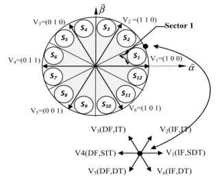
DTC with 12 sectors
The 12 sectors method uses the same block diagram as shown in figure 2; but the switching table now consists of 12 non null voltage vectors, to be selected.
The flux angle now lies on one of the 12 sectors as shown in figure 4.
V3(DF,IT) V2(IF,IT) V6(IF,DT) V5(DF,DT) V1(IF,SDT) V4(DF,SIT) βr αr V2 =(1 1 0) V1=(1 0 0) V3=(0 1 0) V4=(0 1 1) V5=(0 0 1) V6=(1 0 1) Sector 1 S1 S2 S4 S3 S5 S6 S12 S11 S9 S10 S8 S7
Fig.4. Different vectors of stator voltages in case of table with 12 sectors.
with:
SI(D)T : Small Increase (Decrease) of Torque. The switching logic is similar to that of a conventional DTC [16].
Table 5 shows the strategy for the first sector and the 12 sector where we can deduce the rests of all sectors.
Table 5. Switching table of DTC with 12 sectors S1 S12
Flux Increase V1 ,V2 and V6 V1 ,V2 and V6 Decrease V3 ,V4 and V5 V3 ,V4 and V5
Torque Increase V2 ,V3 and V4 V1 ,V2 and V3 Decrease V5 ,V6 and V1 V4 ,V5 and V6
7.
DTC experimental results
A. Part 1
The parameters of the IM used in this study and the description of the testbed are given at the end of this paper. For a comparison study, the results are grouped into sets of three.
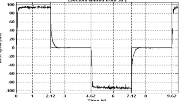
In Figure 5, the rotor speed reaches its reference with a gap of about 4rad / s for the simple table and the table of 12 sectors, the reference of this speed is 100 rad / s. this difference is due to the load which is 15 N.m. In the same test conditions, the rotor speed drops by about 2 rad / s in the case of sectors shifted by 30 ° compared to the other tables, but it may be noted that fluctuations in speed, are less present in the latter strategy compared to the other two strategies.
Fig.5. Rotor Speed, for all strategies of DTC.
The torque has been improved in the last two strategies (Figure 6), but even if it was characterized by annoying fluctuations.
The case of sectors shifted by 30° presents the most remarkable improvement.
Fig.6. Torque response, for all strategies of DTC.
Figure 7 shows the reason why the conventional and the DTC with 12 sectors are not so different, which is confirmed by [16]. DTC with sectors shifted by 30° is well characterized by a different PWM, which gives better improvement in terms of ripples.
Fig.7. Voltage of a stator phase, for all strategies.
In figure 8, the stator flux has fewer ripples in the case of conventional DTC than the other strategies.
This case presents a dilemma for choice between ripples of torque and ripples of flux.
The flux rotation frequency, in the case of sectors shifted by 30 ° is bigger than that of other tables; therefore the flux performs well in these two tables than in the table with sectors shifted, this can interpret the ripples of stator flux.
Fig.8. Stator flux, for all strategies of DTC.
B. Part 2
In the following work, we will choose a scenario for testing the control system, this scenario is summarized in table 6.
Table 6. Scenario simulation for tracking of solar panel.
Where there are clouds, is similar to the sunset, however, the state that follows takes '001' indicating that the panel should turn to the West.
Fig.10. Rotor Speed, for DTC with sectors shifted by 30°
Fig.11. Torque, for DTC with sectors shifted by 30°.
Fig.12. Stator flux, for DTC with sectors shifted by 30°.
To maintain the torque equalling zero, one has to cancel the stator flux, otherwise one is not able to have a zero torque in the moments where the flux and the current are not indicating zero, because the unloaded current is still non null according to (2).
8.
Conclusion
In this work, we have examined and validated the algorithm of a simple DTC, applied to a tracking system in the aim to optimize a global panel solar efficiency.
Three switching tables have been presented and tested; the experimental results show that the table with sectors shifted by 30° can improve the torque ripples which is interesting for the application in issue (tracking system), but not those of the stator flux. Table with 12 sectors can also improve the control slightly, confirming the results of [16], but it reported less interest since it employs a switching table large enough compared to the other two strategies.
This experimental study helps us to adopt the best simple switching table, it is recommended to use the shifted table strategy to implement the tracking system designed for solar system (thermal or photovoltaic).
Description of the testbed
PC: P3(X86 Family 6, Model 8, stepping 6), 866 MHz, 256 MO (Ram), VGA: Matrox Millinium G450 Dual head (32 MO), OS: Windows 2000 pro.
DSPACE: ISA, DSP 1103 PPC Controlled Board.
INVERTER: Two levels (max 100 KHz), IGBT (1200V-50A).
SENSORS:
1, Speed: Universal DIGISINE, DHO5 [BEI-IDEACOD], 2, Current: AM30N 10-100A/1V, (Input: 100A peak max,
DC. 100kHz|output:100-10mV/A, 1V peak max. 3, Voltage: Differential DP1000 with two outputs 10-100
Fig.13. Testbed used in the present study. where:
1: the IM
2: DSPASE consol 3: the two-levels inverter 4: the load (PMSG)
Table 7. IM parameters used in this study
Pole pairs 2
Rated power kW (at 50 Hz) 4 Rated voltage (V) 220/380 Rs (Ω) 1.30 Rr (Ω) 0.91 Ls,r (H) 0.19 M (H) 0.18 J(kg.m²) 0.009 fr (N.m.s/rad) 0.03
Period (s) Event State
(logic) Action (movement)
0 - 2,12 The Sun moves 001 Rotate to the West 2,12- 4,62 Optimal position 011 Lock (no movement) 4,62- 7,12 Sunrise 100 Rotate to the East 7,12- 9,62 Optimal position 011 Lock (no movement) 9,62-10 The Sun moves 001 Rotate to the West
Acknowledgment
This experimental study was conducted within the laboratory IREENA in St Nazaire, University of Nantes. The IREENA's team members find here our appreciation and acknowledgment.
References
[1]. I. Takahashi, and Y. Ohmori, “High-performance Direct Torque Control of an Induction Moto”r. IEEE Transactions on Industry Applications, Vol. 25, March/April 1989, pp. 257-264.
[2]. B.K. Bose, “High Performance Control of Induction Motor Drives”. IEEE, IES Newsletter, Vol. 45, pp. 7-11, Sept. 1998.
[3]. X. Roboam, B. De Fornel and M. Pietrzak-David, Lois de commande directe de couple du moteur asynchrone, chapitre 6, Modélisation Contrôle Vectoriel et DTC, commande des moteurs asynchrones (Laws of direct torque control of asynchronous motor, Chapter 6, Modeling, Vectorial Control and DTC, control of asynchronous motors.) Vol.1, Hermès Science Europe 2000 Edition.
[4]. G.M.A. Sarhan, A.A. Nafeh, M.H. Shalan, “Direct Torque Control of PM Synchronous Motor”. In Journal of Electric Engineering, Vol. 10, 2010, Edition 4, p 24-31.
[5]. B. Mokhtari, A. Ameur, L. Mokrani, B. Azoui and M.F. Benkhoris, “DTC Applied to Optimize Solar Panel Efficiency”. In Proc, IECON’O9, 2-5 November 2009, Proto, Portugal, pp. 1118-1123.
[6]. L. Zhong, M.F. Rahman, W.Y. Hu, K.W. Lim, and M.A. Rahman, “A Direct Torque Controller for Permanent Magnet Synchronous Motor Drives”. IEEE Transactions on Energy Conversion, Vol. 14, September 1999, pp. 637-642.
[7]. A. Ameur, B. Mokhtari, L. Mokrani, B. Azoui, N. Essounbouli and A. Hamzaoui “An Improved Sliding Mode Observer for Speed Sensorless Direct Torque Control Of PMSM Drive With a Three-Level NPC Inverter Based Speed
And Stator Resistance Estimator”. In Journal of Electric Engineering, Vol. 10, 2010, Edition 4, pp.1-9.
[8]. C.G. Mei, S.K. Panda, J.X. Xu and K.W. Lim, “Direct Torque Control of Induction Motor-Variable Switching Sensors”. Conf. Rec. IEEE-PEDS, July 1999, Hong Kong, pp. 80-85.
[9]. C. Lascu, I. Boldea and F. Blaabjerg, “A Modified Direct Torque Control for Induction Motor Sensorless Drive”. IEEE Trans. Ind. Applicat, vol. 36 no.1, Jan/ Feb 2000, pp.122-130.
[10]. C. Martins, X. Roboam, T.A. Meynard and A.S. Caryalho, “Switching Frequency Imposition and Ripple Reduction in DTC Drives by Using a Multilevel Converter”. IEEE Trans. Power Electron., vol. 17, issue 2, March 2002, pp. 286-297. [11]. M. Cirrincione, M. Pucci and G. Vitale, “A novel direct
torque control of an induction motor drive with a three-level inverter”. IEEE Bologna Power Tech Conference, June 23-26, Italy, 2003, Vol. 3, pp.7.
[12]. E. Hossain, R. Muhida, and A. Ali,, “Efficiency improvement of solar cell using compound parabolic concentrator and sun tracking system”, IEEE Electrical Power & Energy Conference (EPEC 2008), Vancouver, Canada, October 6 - 7, 2008.
[13]. C. Alexandru, M. Comsit, “The energy balance of the photovoltaic tracking systems using virtual prototyping platform”. European Electricity Market, 2008. EEM 2008, 5th International Conference on, 28-30 May 2008
[14]. R. Lau, H. Kim; M. Pang, A. Neidhardt, A. Cisneros, V. Kaul, “Self-correcting Adaptive Tracking System”. Military Communications Conference, 2008. MILCOM 2008, IEEE, 16-19 Nov. 2008, pp.1-7.
[15]. C. Jung-Sik, K. Do-Yeon, P. Ki-Tae, C. Chung-Hoon, C. Dong-Hwa, “Design of Fuzzy Controller based on PC for Solar Tracking System”. Smart Manufacturing Application, ICSMA 2008. International Conference on, 9-11 April 2008, pp.508 – 513.
[16]. B.S. Kumar, R.A. Gupta, and R. Kumar, “12-Sector Methodology of Torque Ripple Reduction in a Direct Torque Controlled Induction Motor Drive”. SICE-ICASE International Joint Conference 2006, Oct. 18-21, 2006, in Bexco, Busan, Korea, pp. 3587-3592.