A DEVELOPMENT AND ASSURANCE PROCESS FOR MEDICAL
APPLICATION PLATFORM APPS
by
SAM PROCTER
B.S., University of Nebraska – Lincoln, 2009
M.S., Kansas State University, 2011
AN ABSTRACT OF A DISSERTATION
submitted in partial fulfillment of the
requirements for the degree
DOCTOR OF PHILOSOPHY
Department of Computing and Information Sciences
College of Engineering
KANSAS STATE UNIVERSITY
Manhattan, Kansas
Abstract
Medical devices have traditionally been designed, built, and certified for use as monolithic units. A new vision of “Medical Application Platforms” (MAPs) is emerging that would enable compositional medical systems to be instantiated at the point of care from a collection of trusted components. This work details efforts to create a development environment for applications that run on these MAPs.
The first contribution of this effort is a language and code generator that can be used to model and implement MAP applications. The language is a subset of the Architecture, Analysis and Design Language (AADL) that has been tailored to the platform-based envi-ronment of MAPs. Accompanying the language is software tooling that provides automated code generation targeting an existing MAP implementation.
The second contribution is a new hazard analysis process called the Systematic Analysis of Faults and Errors (SAFE). SAFE is a modified version of the previously-existing System Theoretic Process Analysis (STPA), that has been made more rigorous, partially composi-tional, and easier. SAFE is not a replacement for STPA, however, rather it more effectively analyzes the hardware- and software-based elements of a full safety-critical system. SAFE has both manual and tool-assisted formats; the latter consists of AADL annotations that are designed to be used with the language subset from the first contribution. An automated report generator has also been implemented to accelerate the hazard analysis process.
Third, this work examines how, independent of its place in the system hierarchy or the precise configuration of its environment, a component may contribute to the safety (or lack thereof) of an entire system. Based on this, we propose a reference model which generalizes notions of harm and the role of components in their environment so that they can be applied to components either in isolation or as part of a complete system. Connections between these
formalisms and existing approaches for system composition and fault propagation are also established.
This dissertation presents these contributions along with a review of relevant literature, evaluation of the SAFE process, and concludes with discussion of potential future work.
A DEVELOPMENT AND ASSURANCE PROCESS FOR MEDICAL
APPLICATION PLATFORM APPS
by
Sam Procter
B.S., University of Nebraska – Lincoln, 2009
M.S., Kansas State University, 2011
A DISSERTATION
submitted in partial fulfillment of the
requirements for the degree
DOCTOR OF PHILOSOPHY
Department of Computing and Information Sciences
College of Engineering
KANSAS STATE UNIVERSITY
Manhattan, Kansas
2016
Approved by: Major Professor John Hatcliff
Copyright
Sam Procter
Abstract
Medical devices have traditionally been designed, built, and certified for use as monolithic units. A new vision of “Medical Application Platforms” (MAPs) is emerging that would enable compositional medical systems to be instantiated at the point of care from a collection of trusted components. This work details efforts to create a development environment for applications that run on these MAPs.
The first contribution of this effort is a language and code generator that can be used to model and implement MAP applications. The language is a subset of the Architecture, Analysis and Design Language (AADL) that has been tailored to the platform-based envi-ronment of MAPs. Accompanying the language is software tooling that provides automated code generation targeting an existing MAP implementation.
The second contribution is a new hazard analysis process called the Systematic Analysis of Faults and Errors (SAFE). SAFE is a modified version of the previously-existing System Theoretic Process Analysis (STPA), that has been made more rigorous, partially composi-tional, and easier. SAFE is not a replacement for STPA, however, rather it more effectively analyzes the hardware- and software-based elements of a full safety-critical system. SAFE has both manual and tool-assisted formats; the latter consists of AADL annotations that are designed to be used with the language subset from the first contribution. An automated report generator has also been implemented to accelerate the hazard analysis process.
Third, this work examines how, independent of its place in the system hierarchy or the precise configuration of its environment, a component may contribute to the safety (or lack thereof) of an entire system. Based on this, we propose a reference model which generalizes notions of harm and the role of components in their environment so that they can be applied to components either in isolation or as part of a complete system. Connections between these
formalisms and existing approaches for system composition and fault propagation are also established.
This dissertation presents these contributions along with a review of relevant literature, evaluation of the SAFE process, and concludes with discussion of potential future work.
Table of Contents
List of Figures xiii
List of Tables xvii
Acknowledgements xviii
1 Introduction 1
2 Literature Review 5
2.1 Integrating Medical Devices . . . 5
2.1.1 Medical Application Platforms . . . 5
2.1.2 The Integrated Clinical Environment . . . 8
2.1.3 The Medical Device Coordination Framework . . . 9
2.1.4 Connecting Medical Devices . . . 13
2.1.5 A PCA Interlock App . . . 15
2.2 System Safety . . . 17
2.2.1 A Note on Terminology . . . 17
2.2.2 Hazard Analyses . . . 19
2.2.3 The Fault Propagation and Transformation Calculus . . . 25
2.2.4 Documenting Safety: Assurance Cases . . . 26
2.2.5 Standardization Efforts . . . 29
2.3 Architecture Modeling . . . 38
2.3.2 Architecture Modeling Techniques . . . 41
2.3.3 Technological Approaches to Architecture Modeling . . . 44
3 An AADL Subset for MAP Apps 54 3.1 Introduction . . . 54
3.1.1 App Development Environment Vision . . . 56
3.1.2 Mechanization and Regulatory Authorities . . . 57
3.2 Why AADL for MAPs? . . . 58
3.2.1 Medical Application Platforms . . . 58
3.2.2 Architecture Analysis & Design Language . . . 60
3.2.3 Why subset AADL? . . . 61
3.3 Language Walkthrough . . . 63
3.3.1 Preliminary tasks: Types and Default Properties . . . 65
3.3.2 The AADL System . . . 67
3.3.3 The AADL Process and Device . . . 69
3.3.4 The AADL Thread . . . 72
3.4 Code Generation and Instantiation . . . 73
3.4.1 Executable Code Skeletons . . . 73
3.4.2 App Configuration . . . 77
3.4.3 Launching the App . . . 79
3.5 Tailoring AADL to a Domain . . . 81
4 The SAFE Process 83 4.1 Core Concepts . . . 85
4.1.1 Successor Dangers . . . 87
4.1.2 Manifestations . . . 89
4.1.4 Formality in Causation and Decomposition . . . 94
4.1.5 Terminology . . . 99
4.1.6 Parallel and Compositional Aspects of SAFE . . . 101
4.2 Activity 0: Fundamentals . . . 103
4.2.1 System-Level Fundamentals . . . 104
4.2.2 Specifying a Control Structure . . . 113
4.3 Activity 1: Externally Caused Dangers . . . 117
4.3.1 Successor Dangers and Process Models . . . 117
4.3.2 Deriving an Element’s Dangers . . . 123
4.3.3 Documenting External Interactions . . . 126
4.4 Activity 2: Internally Caused Faults . . . 131
4.4.1 Eliminating Classes of Faults . . . 132
4.4.2 Documenting Internal Faults . . . 134
4.5 Assessment . . . 138
4.5.1 Objective Attributes . . . 138
4.5.2 Subjective Attributes of Previous Hazard Analyses . . . 142
4.5.3 Subjective Evaluation of SAFE . . . 147
4.5.4 Threats to Validity . . . 153
5 Theoretical Foundations 154 5.1 Introduction . . . 154
5.1.1 Hierarchical Depth, Component Role, and Undesirability . . . 155
5.2 Process . . . 157
5.3 Formalisms . . . 163
5.4 Compositionality . . . 167
5.4.2 Compositional Approach: App . . . 175
5.4.3 Compositional Approach: Pump . . . 178
5.4.4 Analyzing the Composed System . . . 181
5.4.5 Refining a Component . . . 185
5.5 Fault Propagation and Transformation . . . 190
5.5.1 Example System . . . 191
5.5.2 Differences Found . . . 193
5.5.3 Methodological Discussion and Vocabulary . . . 195
5.6 Gaps in the Analysis . . . 198
6 Evaluation 201 6.1 Analysis of the PCA Interlock System . . . 201
6.1.1 Previously Discovered Issues . . . 201
6.1.2 Newly Discovered Issues . . . 204
6.1.3 Threats to Validity . . . 207
6.2 Proposed User Study . . . 207
6.2.1 Methodology . . . 207
6.2.2 Hypothesis . . . 209
6.2.3 Threats to Validity . . . 210
6.2.4 Further Studies . . . 210
7 Future Work and Conclusions 212 7.1 Future Work . . . 212
7.1.1 MDCF Architect . . . 212
7.1.2 The SAFE Process . . . 214
7.1.3 Theoretical Work . . . 216
Bibliography 218
A SAFE Process 233
B SAFE Worksheets 254
List of Figures
2.1 The ICE Architecture, figure adapted from [1, 2] . . . 8
2.2 The MDCF Architecture, figure adapted from [1] . . . 10
2.3 The App Developer’s view of the PCA Interlock Application . . . 16
2.4 The MDCF view of the PCA Interlock Application . . . 18
2.5 The relationship between the terms “Fault,” “Error,” and “Failure,” repro-duced from Figure 11 of [3] . . . 18
2.6 An example FTA for the PCA interlock scenario, adapted from [4] . . . 20
2.7 A control loop from the PCA Interlock example, annotated according to STPA. Adapted from [4] . . . 24
2.8 An example of the Claims-Argument-Evidence assurance case format’s graph-ical notation that is equivalent to Figure 2.9. Adapted from [5, pg. 56] . . . 27
2.9 An example of the Claims-Argument-Evidence assurance case format’s tex-tual notation that is equivalent to Figure 2.8. Adapted from [5, pg. 56] . . . 27
2.10 A graphical view of an AADL component. The textual view of this component is shown in Figures 2.12 and 2.13. . . 47
2.11 A simple AADL property set . . . 47
2.12 A simple AADL component type. A graphical view of this component is shown in Figure 2.10. . . 48
2.13 A simple AADL component implementation. A graphical view of this com-ponent is shown in Figure 2.10. . . 49
2.15 Timing related errors in the EMV2 error type hierarchy, from [6] . . . 52
2.16 Timing related errors extended first to the ICE Architecture (red) and sub-sequently the PCA interlock app (blue), from [6] . . . 53
3.1 The three-part code generation vision . . . 64
3.2 The SpO2 datatype used in the app excerpt . . . 65
3.3 The default properties used in the app excerpt . . . 66
3.4 The top-level app excerpt architecture via the AADL system component . . 68
3.5 An AADL process specification used in the app excerpt . . . 70
3.6 An AADL device used in the app excerpt . . . 71
3.7 Two AADL thread interfaces used in the app excerpt . . . 72
3.8 Executable “skeletons” produced by the translator . . . 74
3.9 The same “skeletons” complete with business logic . . . 75
3.10 A partial logic-module “supertype” which hides most of the autogenerated code . . . 76
3.11 An excerpt of the app’s overall layout configuration . . . 78
3.12 The logic module’s configuration . . . 80
4.1 The two-state concept of a hazard . . . 87
4.2 The two-state concept of undesirability . . . 89
4.3 The range of ways that input can be incorrect . . . 91
4.4 The PCA interlock loop in its clinical context . . . 95
4.5 An expanded view of the shaded region from Figure 4.4 . . . 99
4.6 The dependencies between the steps in SAFE . . . 101
4.7 The fundamentals property type definition . . . 105
4.8 The system-level fundamentals worksheet used in M-SAFE . . . 106 4.9 The system-level fundamentals of the PCA Interlock Scenario in M-SAFE . 106
4.10 The fundamentals property for the PCA Interlock Scenario . . . 107
4.11 The PCA Interlock Scenario’s patient in AADL . . . 108
4.12 Possible system boundaries for different levels of abstraction in the PCA Interlock scenario . . . 113
4.13 The PCA Pump interface type in AADL . . . 118
4.14 The PCA Pump interface implementation in AADL . . . 119
4.15 The component worksheet used in M-SAFE. . . 120
4.16 A partial M-SAFE component worksheet for the PCA Pump used in the PCA Interlock scenario. . . 121
4.17 Datatypes used in the PCA Interlock’s Process Model . . . 123
4.18 The six failure domains from Aviˇzienis et al. encoded in AADL’s EMV2 . . 124
4.19 The PCA Pump’s possible manifestations, extending from the base failure domains in Figure 4.18 . . . 125
4.20 Property types used in Activity 1 of SAFE . . . 129
4.21 Property types used in Activity 2 of SAFE . . . 137
5.1 Semantic objects in our formalism . . . 158
5.2 Labels used by our formalism . . . 159
5.3 A hypothetical “SafePCA Device” in its environment . . . 169
5.4 The app logic in its environment . . . 176
5.5 A basic PCA pump in its environment . . . 179
5.6 The app logic and pump in their combined environment . . . 181
5.7 An implementation of the preliminaries and setup code that enable an imple-mentation of the specification in Section 5.4.2 . . . 186
5.8 Java code to check that the invariant from Section5.4.2is maintained by the implementation . . . 187
5.9 An implementation of the app logic that refines the specification from Section
5.4.2 . . . 188
5.10 An implementation of the environment that refines the specification from Section5.4.2. . . 189
5.11 The SafePCA device and environment with FPTC behaviors . . . 191
5.12 The first step of FPTC on the SafePCA and patient . . . 193
5.13 The final, stabilized FTPC graph of the SafePCA and patient . . . 194
List of Tables
2.1 An example FMEA Worksheet for the PCA Interlock scenario, adapted from
[4,7] . . . 22
3.1 AADL syntax elements and their MAP app mappings . . . 61
3.2 AADL properties used in our MAP-targeted subset . . . 69
4.1 The 18 combined fault classes used in SAFE . . . 94
4.2 Dependencies between the steps of SAFE . . . 102
4.3 Example safety fundamentals for the PCA Interlock scenario . . . 104
4.4 Summary of objective attributes of major hazard analyses . . . 139
4.5 Mapping from STPA’s Step 1 Guidewords to the service failure modes from [3]139 4.6 A mapping from STPA’s fault-related guidewords to Aviˇzienis et al.’s fault classes . . . 140
4.7 Conjectured, subjective attributes of major hazard analyses . . . 142
5.1 Examples of the formalisms applied to components of the PCA Interlock scenario . . . 160
Acknowledgments
First and foremost I would like to thank my major professor, Dr. John Hatcliff, for all the advice, help, and support he has given me throughout the course of my PhD work. I feel very fortunate to have been able to study under him, Dr. Robby, and the other faculty in the SAnToS Laboratory, and to have worked with all the students that have been members. I would also like to thank my committee members for their feedback on this research; I have in particular appreciated Dr. Eugene Vasserman’s kind words and unique perspective on the challenges of system safety. Similarly, the advice of Dr. David Schmidt has been a great help at various points throughout my graduate studies.
My family—both my parents, as well as my brother and his husband—have been a source of great support and inspiration, and I would not have made it nearly as far as I have without them. Similarly, my friends—in town and across the country, in graduate school and in industry—have listened to my complaints and cheered my successes, and for that I am extremely grateful.
This work was supported in part by the US National Science Foundation (NSF) awards CNS-1239543, CNS-1355778, and CNS-1446544.
Chapter 1
Introduction
John Knight wrote that “Safety-critical systems are those systems whose failure could result in loss of life, significant property damage, or damage to the environment” [8]. Safety-critical software engineering, then, is the practice of building software used in these systems. Build-ing software correctly is challengBuild-ing regardless of application, but it is especially difficult when the impact of a system failure is so high.
One domain where many systems are safety-critical is in medicine. Traditionally, medical devices have been built as standalone units, following similarly standalone safety-engineering processes. Increasingly, though, there is a desire for medical devices to work together— through some form of automated coordination—to perform various types of clinical proce-dures. These range from the straightforward, e.g., updating the electronic medical record automatically with the readings from a physiological monitor, to the advanced, e.g., auto-matically disabling the administration of an analgesic when a patient shows signs of respi-ratory distress.
Typically, the safety evaluations of these medical devices also treat them as monoliths: existing safety procedures (like hazard analyses) considered only completed systems. These procedures are not only de facto standards, known and used in industry, but are de jure standards as well: current evaluation processes for the United States Food and Drug
Ad-ministration (FDA) only consider completed systems.
There are a number of concepts that have enabled more rapid construction (though not necessarily analysis) of software- and hardware-based systems, including:
Interoperability: Systems are increasingly thought of not as standalone units but as
components that must interoperate in order to achieve the system’s overall goal. Such an approach also enables component reuse.
Reuse: In response to rising demands on development resources, previously developed
components are often reused in new systems. Some are even developed for a number of potential uses, rather than for one particular system.
Component-/Model-Driven Development: Rather than have developers directly
im-plement required functionality, system construction now often takes place via models of system components. In this paradigm, components can be thought of as building blocks that are specified and integrated before being automatically translated into system components.
Platforms: Components need access to underlying services that, e.g., enable real-time
communication and govern access to shared computational resources. These under-lying services are collectively referred to as a platform; many modern development approaches first establish the platform to be used and then build system functionality around its capabilities and limitations.
Systems-of-Systems: In many cases each component and the platform itself can be
built, reasoned about, and sometimes used independently as standalone systems. Thus, what are referred to as “systems” are often actually hierarchical systems-of-systems that have interesting, recursive properties. Though some researchers object to the use of this term [9], we feel that it speaks to the concept of systems as a collection of cooperating elements that can all (to varying extents) also stand alone.
All of these concepts can combine to enable a number of beneficial, “marketplace”-like aspects for system development within medicine, but with this ease of development comes a corresponding increase in the difficulty of safety assurance. Safety assessment in a multi-vendor, component-based domain can be not only challenging but quite slow if performed using traditional techniques, which removes much of the benefit of these more modern development approaches.
Work in this area has, to some extent, addressed the challenges of safety-critical and distributed systems. Many of these techniques prioritize architectural specifications as a “single source of truth” upon which various annotations targeting particular “quality at-tributes” can be added [10, 11]. Once all or part of the system’s architecture is annotated, supported analyses (either manual or tool-supported) can be performed.
What is needed, then, is an examination and demonstration of the suitability of these software engineering techniques to the challenge of safely constructing and evaluating medi-cal device integration software. This work describes the motivations and results of an effort to perform this task.
Specifically, the contributions of this work are:
1. Theory – Hazard Environment Hierarchy: I examine the relationship between a
com-ponent and its environment in the context of system safety. I believe that a pattern ex-ists in the vertical decomposition of systems which makes the component-environment relationship a hierarchically repetitive one, and this repetition can be exploited to increase the formality of existing hazard analyses. I propose a collection of definitions that, while by no means a full formalization or end-to-end theory, move the previously disparate topics of system safety analysis and compositional verification one step closer together.
2. Process – Hazard Analysis: Leveraging the realizations from 1, I propose significant
modifications to an existing systems-based hazard analysis. These modifications result in a process that, I believe, requires less user-expertise and is more repeatable than the
status quo. Additionally, a subset of these modifications are designed to be integrated with a semi-formal description of a system’s architecture, the increased rigor of which may bring additional analytic power and reduced analysis time.
3. Tooling:
(a) Code Generation: I demonstrate existing approaches to architectural
specifica-tion and automated system construcspecifica-tion by developing a software prototype that will take a specification of a medical system as input and produce as output a runnable version of that system. This enables a very close alignment of system model and executable artifacts, saving developer time and enhancing the quality of model-based analyses.
(b) Report Generation: Leveraging the code generation described in 3.(a), I will
describe additional annotations that align with and support the hazard analysis process from 2, fully integrating it with a semiformal description of a system’s architecture. The software prototype from 3.(a) will then be extended to support automated generation of a hazard analysis report usable by a number of system stakeholders.
Throughout this work we use as a running example the “PCA Interlock” clinical sce-nario, which is introduced in Section 2.1.5. This work is being done—in collaboration with engineers from UL and the United States Food and Drug Administration—in the context of an existing standard governing integrated clinical environments as well as an upcoming standard addressing medical device interoperability. [2]
Chapter 2
Literature Review
In this section, I examine the three areas that this work draws from. First, I review the literature surrounding the integration of medical devices, primarily in the context ofMedical
Application Platforms. Second, I review the relevant literature in the system safety domain,
with particular attention paid to hazard analysis techniques and medical system safety standardization efforts. Third, I review the literature associated with system and software architecture modeling, focusing on formal architecture descriptions that enable automated system construction and analyses.
2.1
Integrating Medical Devices
2.1.1
Medical Application Platforms
Though the concept of integrating medical devices has been circulating for some time (e.g., [12,2]), in [13], Hatcliff et al. introduce the termMedical Application Platform (MAP) and define it as “a safety- and security-critical real-time computing platform for (a) integrating heterogeneous devices, medical IT systems, and information displays via a communication infrastructure and (b) hosting application programs (i.e.apps) that provide medical utility via the ability to both acquire information from and update/control integrated devices, IT
systems, and displays.” They go on to explain the need for the concept, mentioning an aging population that is projected to increase demands for healthcare services and a focus on outcome-based medicine driving “quality enhancements and cost reductions.”
Hatcliff et al. further explain that in other, non-safety-critical domains, there are three trends which are driving integration efforts: increasing levels of device interoperability, a
platform approach (where the entire ecosphere of hardware and software components are
governed by a single entity, e.g., Apple’s governance of iOS), and the embrace of a systems
perspective, which encourages the conception of components as (sub)systems, i.e., taking a
systems-of-systems approach. This fits well with Checkland’s definition of a system, which is “A set of elements connected together, which form a whole, this showing properties which are properties of the whole, rather than properties of its component parts.” [14]
These platforms allow the dynamic integration of medical devices and purpose-built software in order to serve some clinical need. Hatcliff et al. explain that there are four missing elements, the absence of which block the implementation and industrial adoption of MAPs:
Interoperability Standards: Coordinating the actions of disparate entities in a
market-place requires some form of incentives. Hatcliff et al. point out that “there has been significant activity on standards” targeting the exchange of information, but existing works “do not address the technical requirements for device connectivity, safety, and security.”
Appropriate Architectures: Architectures addressing the challenges faced by MAPs
exist in other domains, such as Integrated Modular Avionics (IMA) for aviation, or Multiple Independent Levels of Security (MILS) in security-oriented fields [15, 16]. These are not, however, immediately applicable to the medical field.
Regulatory Pathway: Regulatory agencies, like the US Food and Drug Administration,
a composable system like those enabled by MAP technology, though, would be an arduous task indeed: the number of possible combinations given only a small number of devices and applications would still be quite large.
Interoperability Ecosystem: The phrase “interoperability ecosystem” (introduced in
[13], renamed to ecosphere and greatly expanded in [17, 1]) refers to the complete environment surrounding a platform. King et al. define it as the “set of devices, software applications and computational platforms intended to interact with one [an-other]; the stakeholders that organize, manufacture, and use these products; as well as the explicitly defined processes that are followed to develop, certify, and use these products.”
In addition to the removal of these roadblocks, Hatcliff et al. also identify a number of technologies necessary to enable the MAP vision. They group these technologies into four main areas:
1. Architecture and Interfacing: Interoperable architecture, compliance-checkable
inter-faces, rich interface description language, etc.
2. Platform Technology: Static verification, composability, global resource management,
automated trust and security services, etc.
3. Safety, Effectiveness, and Certification: Component-wise regulation, third-party
cer-tification, etc.
4. Ecosystem Support: Consensus-driven component specifications, development
envi-ronment for MAP apps, etc.
It is in the fourth area, specifically in the development environment, that this work makes the bulk of its contribution. There is a great deal of overlap between goal areas, though, so a common development environment would include support for a number of other goals as
Integrated Clinical Environment (ICE) D ata Lo gg er
IC
E
Man
ag
er
…
Medical Device ICE Equipment Interface 1 2Supervisor
2aNetwork
Controller
2b 2cFigure 2.1: The ICE Architecture, figure adapted from [1, 2]
well by supporting, e.g., interface checking; static verification tooling; repeatable analysis processes for analysts, regulators and certifiers, etc.
2.1.2
The Integrated Clinical Environment
In 2009, ASTM International released the standard ASTM-F2761 “Medical Devices and Medical Systems – Essential safety requirements for equipment comprising the patient-centric integrated clinical environment (ICE) – Part 1: General requirements and conceptual model” [2]. The standard describes the high-level functional (i.e., non-architectural/non-implementation) requirements for a possible MAP implementation. Figure 2.1 shows the ICE components (descriptions adapted from [2]):
1. Equipment Interface: Though no description is given of the ICE Equipment Interface (only examples), it is understood to enable a piece of equipment (e.g., a medical device) to communicate with the ICE system
2. Manager: The ICE Manager is the name used to refer to the collection of the ICE
Supervisor, Network Controller, and Data Logger.
(a) Supervisor: The ICE Supervisor is responsible for either ensuring that the
re-quirements (both functional and non-functional) provided by the Network Con-troller can deliver the intended use of the ICE Supervisor, or for generating an alarm if the requirements of a running system can no longer be met.
(b) Network Controller: The ICE Network Controller is responsible for ensuring
the delivery of the functional capabilities, “in accordance with non-functional requirements” of the connected devices to the ICE Supervisor, or generating an alarm if the connection fails in some way.
(c) Data Logger: The data logger provides a time-indexed recording of “the accessible
‘state-of-the-clinical environment’ ” This enables any problems that are encoun-tered to be diagnosed post-hoc, be they related to safety, security, or functional concerns.
Though there are a small number of different ICE implementations from both academic and commercial suppliers, this focuses on one in particular, theMedical Device Coordination
Framework.
2.1.3
The Medical Device Coordination Framework
In their 2009 work, King et al. described the Medical Device Coordination Framework (MDCF), which is an open-source implementation of the ICE standard developed at Kansas State University and later the University of Pennsylvania [18]. The MDCF, and its associ-ated tooling, has been under near-continuous development since.
Medical Device Coordina/on Framework (MDCF) App
…
ICE-‐Compa/ble Equipment…
1 D ata Lo gg erIC
E
Man
ag
er
Re so ur ce Man ag er App Mgr. App DB Services App V.M.
Supe
rv
isor
Dev. Mgr. Message Bus Device DB
N
etw
or
k
Co
ntr
ol
le
r
6 5 4 3 2 7Figure 2.2: The MDCF Architecture, figure adapted from [1]
Kim et al. recently described how the MDCF implements the ICE Architecture [1]1. Figure2.2shows a decomposition of the ICE components, the addition of separate architec-tural elements representing application logic and a global resource manager, and the seven interfaces over which the ICE components interact. MDCF-specific components are outlined in black, interfaces are thick-dashed lines, and ICE components are outlined in grey.
The MDCF specific component additions Kim et al. describe are:
1. App: Software applications that guide the integration of medical devices to do some-thing clinically meaningful. Though these are executed in the Supervisor, they are developed and typically analyzed as architecturally independent. Note that the term 1An earlier description can be found in Hatcliff et al.’s ICCPS 2012 paper. [13]
used in the ICE standard is “Application logic,” rather than app.
2. Resource Manager: Enforcing the quality-of-service specifications of both apps and
devices requires global resource management involving the allocation and monitoring of networking and computing resources (e.g., channels and CPU time, respectively). The MDCF relies on the resource manager provided by King’s MIDAS [19].
3. Supervisor:
(a) App Virtual Machine: Apps are envisioned to be executed in isolated
environ-ments (e.g., separation kernels [16]). As of this writing, this feature is not imple-mented – apps are executed as written on the shared Java virtual machine.
(b) App Database: Stores the names and configuration schemata of app
implemen-tations. Executable logic is looked up at launch time based on the app’s name.
(c) App Manager: Handles the instantiation/connection (including the verification
of digital certificates), monitoring, and termination of instantiated applications.
(d) Services: A collection of services that expose the functionality of the app manager
(e.g., app launch) to the clinical user.
4. Network Controller:
(a) Device Database: Stores identity information and capability descriptions of
de-vices that have been approved to work with the MAP. This allows individual healthcare delivery organizations (HDOs, e.g., hospital) to restrict which devices are usable on their network.
(b) Device Manager: Similar to the app manager, this module handles the
authenti-cated connections of ICE compatible equipment.
(c) Message Bus: The actual communication infrastructure which handles the
Kim et al. also specify seven interfaces (identified by circled numbers in Figure 2.2) that the components use to communicate with one another. We restate these interfaces here, and adopt the notationA →B which signifies that component Auses an interface provided
by component B:
1. Platform → Devices: The platform uses this interface to creates instances of the
device’s supported communication exchanges. For example, if the device supports a requester/responder mode of interaction, this interface would allow its creation and binding to appropriate network channels.
2. Devices → Platform: Devices use this interface to connect to and authenticate with
the platform.
3. Supervisor → Devices via Network Controller: The supervisor uses this interface to
query available devices. An example of this usage would be when an app is requesting some set of device capabilities; the check to see if those capabilities are present would go through this interface.
4. Apps → Supervisor: This interface allows apps to request platform services, like the
reservation of computing or networking resources.
5. Data Logger→Network Controller: This interface is used by the data logger to retrieve
messages sent across the network from the network controller.
6. Network Controller → Data Logger: This interface is used by the network controller
to get messages stored by the data logger for playback. This is used for, e.g., post-hoc/forensic analysis.
7. Supervisor→Resource Manager: This interface is used by the supervisor to request the
allocation of computing or networking resources, typically on behalf of an application that a clinician would like to launch.
2.1.4
Connecting Medical Devices
When the term “device interconnectivity” is used in the medical domain, its precise defi-nition is rarely made explicit; rather, it is typically understood to mean “interoperability.” Work in the field of simulation theory has led to the proposal of different “types” or “levels” of interoperability, but most recognize at a minimum the distinction between two compo-nents being able to “interconnect” (e.g., use a similar communication protocol, data format, etc.) and to “interoperate” (e.g., shared understanding of assumptions and semantics).
Petty and Weisel (who focus on simulation systems, though we believe their definitions work in this domain as well) discuss composability, which they define as “the capability to select and assemble. . . components in various combinations into valid. . . systems.” They further explain that there are two perspectives from which composability can be understood:
the engineering perspective, which focuses on syntactic composability (i.e., “whether the
components can be connected”) and the modeling perspective, which focuses on semantic
composability (i.e., whether the computation of the composed system is semantically valid”) [20].
Syntactic Interoperability
The primary concern of syntactic interoperability is the connection between two devices, or between a single device and some middleware. Unfortunately efforts in this area have not yet converged onto a single technology or style. Early work, like the first versions of the MDCF, used the Java Messaging Service (JMS) [18], which is an API that describes a peer-to-peer messaging service; JMS has both open-source and hardened commercial implementations [21]. Modern implementations of the MDCF can be configured to use either a purpose-built message-bus provided by MIDAS or the Data Distribution Service (DDS) [19, 22]. Some commercial MAP implementations (e.g., Docbox) use DDS, while others (e.g., Dr¨ager) use a purpose-built web-service framework [23].
were in general well suited to publish-subscribe (pub-sub) architectures. Pub-sub works well because a number of MAP apps may be operating on the same patient at the same time, so allowing multiple apps to efficiently read from the same physiological monitoring device efficiently was a high priority. See, for example, [18] for a discussion of the performance aspects of a JMS implementation of the MDCF in various fan-in and fan-out topologies using a range of message sizes and types. Typical MAP implementations use an explicit invocation style of pub-sub, in that the underlying networking middleware routes messages to particular components, but those components themselves are responsible for implementing handlers for event or message arrival. Another advantage of pub-sub is the decoupling of data producers from consumers [11] (all but a necessity in a compositional plug-and-play system like MAPs), though competing concerns like data privacy and security can, at times, require some level of coupling.
While pub-sub works well for reading physiological data from a number of sensors, it is less straightforward to use in more advanced MAP apps that require device control. Since it is unnecessary (or possibly even inappropriate) to have commands sent from a logic module to a specific device broadcast widely, point-to-point communication is, in these cases, preferable to pub-sub. While it is possible to have per-device topics (a strategy employed by, e.g., the MDCF); one advantage of Dr¨ager’s web-service architecture is the explicit inclusion of point-to-point (discussed in their work as request-response) style connections for private communications and device control [23].
Semantic Interoperability
The issue of semantic interoperability, or the challenge of ensuring equivalency between similar values and concepts across disparate components (e.g., medical devices, app logic modules, etc.), is one best addressed by domain (i.e., medical) experts. To that end, we have looked to relevant medical standards—in particular, IEEE 110732—which has two goals: to 2Note that while IEEE 11073 contains specifications for both semantic and syntactic interoperability, syntactic interoperability is quite well treated by software engineering literature. We use the standard
“provide real-time plug-and-play interoperability for patient-connected medical devices” and to “facilitate the efficient exchange of vital signs and medical device data, acquired at the point-of-care, in all health care environments.” [24]
At a high level, the standard focuses on two topics: nomenclature and the “domain information model” (DIM). As the name implies, the nomenclature sections of the standard give a semantic coding for a range of physiological categorizations (e.g., alerts, body sites, metrics, etc.). The DIM, on the other hand, “is an object-oriented model that consists of objects, their attributes, and their methods, which are abstractions of real-world entities in the domain of. . . medical devices.” [25]. The full family of standards includes refinements for specific device families (e.g., pulse oximeters) and is broadly split into those devices used for personal health and those used at the point of care.
While our examples draw inspiration from—and where possible align with—IEEE 11073, we do not use it outright for two main reasons. First, device interconnectivity is only a part of the full MAP vision, and IEEE 11073 does not include facilities for, e.g., hosting/execution of application logic. Second, and more practically, the standard follows an object-oriented, dynamic discovery style of capability description, which both prevents static knowledge (and thus static analysis) of a system and makes makes the creation of robust application logic more complex. That is, applications will have to be responsible for implementing a potentially large number of code paths, depending on the result of the various dynamic capability queries.
2.1.5
A PCA Interlock App
One of the most well-studied MAP apps is the PCA interlock scenario [26, 27, 28]. The app deals with an unfortunately commonplace problem in clinical settings, where following surgery or major trauma, a patient is given a patient-controlled analgesia (PCA) pump to manage her pain. The pump, which may or may not administer a constant, low rate primarily as a source of knowledge of domain-specific semantic aspects.
Pulse Oximeter
Capnograph PCA Pump
Applica6on Logic EtCO2, Resp. Rate SpO2, Pulse Rate Start / Stop Commands Display Pump Status, Pa6ent Status Pa6ent Analgesic Bolus Requests Breath Refracted Light Treatment Configura6on,
Alarm Clear Clinician
Pu m p S tatu s, Pa6 en t S tatu s
Figure 2.3: The App Developer’s view of the PCA Interlock Application
(sometimes referred to as the “basal” rate) allows a the patient to press a button (sometimes referred to as a “bolus trigger”) to receive a larger dose of analgesic. This interaction is designed to be limiting as patients will typically fall unconscious and be unable to self-administer more analgesic. Various problems exist, however, which can lead to accidental overdoses, e.g., atypical patient pharmacokinetics; a visitor pressing the button for the patient (so-called “PCA-by-proxy”); the patient rolling over onto the trigger while asleep; or incorrect medication, dosage, or pump settings by a clinician [29]. Regardless of cause, an overdose can lead to respiratory depression which can cause serious injury or death.
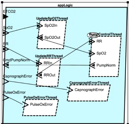
The PCA interlock scenario involves the coordination of one or (typically) several patient monitoring devices, e.g., a capnograph and pulse-oximeter. The app developer’s view of one possible configuration is shown in Figure 2.3. This figure shows the primary elements of the app (medical devices, application logic, etc.) and their connections; note that the solid
arrows represent connections that are explicitly created as part of the app’s instantiation (i.e., network connections) and the dashed arrows represent communication supported, but not directly enabled, by the app. A number of physiological parameters are monitored (e.g., SpO2, ETCO2, and respiratory rate) by application logic for signs of respiratory depression according to some pharmacokinetic model. This model, which is embedded in the app’s logic, can be configured either automatically or by the clinician according to patient history, medical conditions, and treatment status (e.g., the presence of supplemental oxygen). When the model indicates signs of respiratory depression, the PCA pump can be disabled, via a stop command. More sophisticated implementations, where the pump is only enabled for certain windows of time (which precludes situations where the PCA pump is left enabled inappropriately due to network failure) have also been proposed [27]. Note that the app-developer-centric view of Figure 2.3 excludes some MDCF features that are transparent to the developer, e.g., the data logger or the fact that the physiological parameters may come from separate devices. A different view of the application—one made to align with the ICE/MDCF-centric view—is shown in Figure 2.4.
2.2
System Safety
2.2.1
A Note on Terminology
The vocabulary used when discussing safety, unfortunately, varies somewhat between sources. Leveson, who developed the hazard analysis technique this work hews most closely to, uses a set of the standard terms (accident, hazard, etc.) and gives her own definitions [30]. Er-icson, who produced a handbook covering a number of techniques uses similar terms, but gives his own set of definitions [7]. Aviˇzienis et al. give a full taxonomy of terms in [3], the definitions of which in general correspond Leveson and Ericson’s use, though they do not explicitly cite his work. Many standards, e.g., ISO 14971, IEC 80001, and AADL’s EMV2 Annex define their own terms (sourced either from other standards or the standardization
Pa#ent
ICE Equipment Interface conformant Pulse Oximeter, Capnograph, and Pa#ent Controlled Analgesia Pump
RR
Sensor
Data Sensor Data
Cl in ic ian (A pp A dm in is tr ato r) MDCF / ICE Manager App Pump Status, Pa#ent Status Configura#on, Alarm Clear Sensor Data PCA Start / Stop Commands PR Sensor Data SPO2 Logging Data Refracted
Light Refracted Light Breath Breath
Data Logger Display Pump Status, Pa#ent Status Treatment EtCO2
Figure 2.4: The MDCF view of the PCA Interlock Application
Fault Error Failure Fault …
…
Figure 2.5: The relationship between the terms “Fault,” “Error,” and “Failure,” reproduced
from Figure 11 of [3]
body’s style guide) [31, 32, 33]. The end result of this is a considerable difficulty in com-municating precisely about safety as terms may have subtly different meanings to different readers.
Though a full reconciliation of the various terminologies is beyond the scope of this work we recognize the challenges posed and, unless otherwise noted, adopt the terminology and definitions used by Leveson. We adopt the specific terminology (found in [33] and shown graphically in Figure 2.5) that errors are “the difference between a computed, observed,
or measured value or condition and the true, specified, or theoretically correct value or condition,” faults are root causes of errors, and failures are the “termination of the ability of a product to perform a required function.” Put another way, faults are the root causes
of errors and failures are the observable effects of an error.
2.2.2
Hazard Analyses
For as long as systems have been built, some consideration has been paid to their safety. It wasn’t until the middle of the twentieth century, though, that these attempts began to be formalized into more rigorous processes. We discuss three such processes here, the first two, Fault Tree Analysis (FTA) and Failure Modes and Effects Analysis (FMEA) as they are predominant in industry (using [7] as our main source); the third, System Theoretic Process Analysis (STPA) is a newer and more modern approach (detailed in [30]) that forms the basis of much of this work.
Fault Tree Analysis
Fault Tree Analysis, commonly referred to by the initialism FTA, was created by H. Watson and Allison B. Mearns at Bell Labs when they were working on the Minuteman Guidance System [7]. It is a top-down analysis technique that asks the analyst to first select an undesirable event and then consider all the contributory errors that could combine in various ways (typically via AND/OR gates) to cause that event. This process is then repeated recursively until an acceptable level of specificity is met.
An example fault tree for the PCA interlock scenario is shown in Figure 2.6. The top event corresponds to the main accident (or mishap, in the language of [7]) that the PCA interlock app is designed to avoid—an overdose of analgesic being administered to the patient. The figure shows that this could come about if two errors occur simultaneously: the application logic receiving bad physiological data and the error that caused the bad physiological data being undetected. The block that joins these two errors—labelled G1—
Too Large of Dose Allowed G1 Bad Physiological Data Received
Error is not detected G2 Incorrect Physiological Reading Message Garbled by Network SoBware Encoding or Decoding Error G3 Physiological Data within Range Internal DiagnosCcs Fail
Figure 2.6: An example FTA for the PCA interlock scenario, adapted from [4]
dictates the style of this join. Block G2, on the other hand, is anor join, so any of its children (incorrect physiological reading, software encoding or decoding error, or message garbling by the network) could independently cause the parent error: receipt of bad physiological data by the application logic. Figure 2.6 is, of course, only a fragment of a full FTA analysis, which would consider not only more top-level accidents (e.g., underinfusion causing the patient to the be in unnecessary pain, damage to the medical devices caused by inappropriate commands, etc.) and also a deeper analysis of the causes of overinfusion as well.
As FTA has considerable industry support and a history of use, Ericson details extensive theory beyond the basic example given above [7]. Fault tree analyses can be annotated with the likelihoods of particular errors; various statistical methods (Fussell-Vesely importance, Risk Reduction Worth, Birnbaum’s importance measure, etc.) then detail how these likeli-hoods might be combined to arrive at overall probabilities of failure or success. There are also various algorithms for determining subsets of the full fault tree—so-called cut sets— which allow an analyst to focus on particular event chains. Additionally, while the simple graphical notation used in Figure 2.6 forms the core of all fault tree analyses, it has been extended with a number of constructs to allow things like prioritization between gates,
ex-clusivity, inhibition, m-of-n combinations, phasing, timing, dynamism, or even user-specified extensions.
Failure Mode and Effects Analysis
Failure Mode and Effects Analysis is commonly referred to via the initialism FMEA. If the analysis is annotated with criticality information, the technique is sometimes referred to as Failure Mode, Effects, and Criticality Analysis, or FMECA. The technique, which was detailed in MIL-STD-1629A, was developed in the late 1940’s by the United States military [7]. It is a bottom-up analysis technique that asks the analyst to examine the various elements of his system (i.e., hardware components, functional components, software components, etc.) and consider how the element’s failure would impact the behavior of the overall system. The set of hardware failures might include terms like “breakage” or “collapse,” while the set of software failures might include terms like “deadlock” or “garbled message.” This process would then be repeated for each other element in the system.
An example FMECA, following a worksheet provided by Ericson in [7] for the PCA interlock scenario is shown in Table 2.1. This example takes a functional approach (i.e., failure of system functions rather than hardware or software components are considered): the function examined is the provision of SpO2 physiological data to the app. The first row considers the results of this function failing outright, while the second and third consider late delivery or incorrect value delivery. The third column asks for a failure rate, which is unknown for this function but may in some cases be available (typically those involving hardware failures). Causal factors are listed, as are immediate (or local) effects, and then system effects are considered separately. After the method of detection, there is sometimes a column for “current controls” though in this example we skip to the hazard, which should be identified and explained elsewhere. Though the entire worksheet will likely be customized by an organization or standards committee, the “Risk” number is especially likely to be tailored to the domain’s needs. As a general-purpose index, Ericson mentions that the risk index
F ailure Mo d e and Effects A nalysis System: PCA In terlo ck Scenario Subsystem: P ulse Oximeter Device Mo de/Phase: E xe cuti on F unc-tion F ailure Mo de F ail Rate Causal F actors Imme d i-ate Effect System Effect Metho d of Detection Hazard Risk Recommended Action
Pro- vide SpO
2 F ails to pro vide N/A Net w ork failure, device failure SpO 2 not rep orted Unkno wn patien t state App Logic P oten tial for ov e rdose 3D Add safet y timeout
Pro- vides late
N/A Net w ork congestion, transien t device failure SpO 2 not rep orted Unkno wn patien t state App Logic P oten tial for ov e rdose 3C Add safet y timeout
Pro- vides wrong
N/A Device error SpO 2 v alue incorrect Incorrect patien t state None P oten tial for ov e rdose 1E Ha v e device rep ort data qualit y with sensor reading Analyst: Sam Pro cte r Date: Septem b er 26, 2014 P age: 3/14 T able 2.1 : A n example FMEA Workshe et for the PCA Interlo ck sc enario, adapte d fr om [ 4 , 7 ]
from MIL-STD-882 is “generally followed.” The first character is a severity rating, which ranges from 1 (Catastrophic, resulting “in one or more of the following: death, permanent total disability, irreversible significant environmental impact, or monetary loss equal to or exceeding $10,000,000”) to 4 (Negligible, resulting “one or more of the following: injury or occupational illness not resulting in a lost work day, minimal environmental impact, or monetary loss less than$100,000”). The second character is a probability level, ranging from A (Frequent, “Likely to occur often in the life of an item”) to E (Improbable, “So unlikely, it can be assumed occurrence may not be experienced in the life of an item). Probability level F is also sometimes used to signify accidents that have been completely eliminated from possibility. The last column of the worksheet is the recommended action, which specifies what is to be done to eliminate or mitigate the failure.
System Theoretic Process Analysis
After examining a number of failings with safety-critical systems (and the engineering pro-cesses that guided their designs) Leveson recently described the Systems Theoretic Accident
Model and Processes (STAMP) causality model and an associated hazard analysis, System
Theoretic Process Analysis (STPA) [30]. As their names imply, STAMP and STPA differ
most significantly from previous hazard analyses in their use of systems theory, which is de-fined by Leveson as an approach that “focuses on systems taken as a whole, not on the parts taken separately.” This integration leads to the key realization that safety is an emergent property that can be viewed as a control problem. Put another way, unsafe events are the result of inadequate control.
Unlike FMEA, which has the failure of certain system components as its central notion, or FTA, which focuses on avoidance of certain events, STPA is driven by the enforcement
of safety constraints, which are rules that, if properly enforced, prevent inadequate control
of the system.
an-Sensor: Pulse Oximeter
Inadequate Opera-on: SpO2 value incorrect
Inadequate Opera-on: SpO2 value late
Actuator: PCA Pump
Inadequate Opera-on: Doesn’t respond to commands
Controller: App Logic
Process Model Incorrect: Wrongly believes pa:ent to be healthy Flaw in Crea-on: Messages are parsed incorrectly
Controlled Process: Pa:ent
Feedback: PulseOx –> App
Delayed opera-on: Messages late Missing feedback: Messages dropped
Control Ac>on: App –> PCA Pump
Delayed opera-on: Messages late Missing feedback: Messages dropped
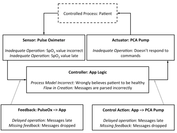
Figure 2.7: A control loop from the PCA Interlock example, annotated according to STPA.
Adapted from [4]
alyzed and prevented or mitigated. STPA contextualizes control actions by placing them into a hierarchical control structure. The most canonical control structure is the control loop, an example of which is shown in Figure2.7. Elements of this control loop are labelled as “Component Role: Component Name” (e.g., the pulse oximeter plays the role of a “sen-sor” in this control loop). The lower half of the components are then labelled with ways that they can contribute to the system being unsafe, in the format “Causality Guideword:
Error.” Procter and Hatcliff describe an early version of the work in this dissertation as (among other goals) an attempt to develop a canonical report format for STPA [4].
2.2.3
The Fault Propagation and Transformation Calculus
Each of the previously designed hazard analyses have as their goal to find the causes of accidents so that they can be eliminated (by a more thoughtful system design) or mitigated by some control. FMEA does this perhaps most explicitly by starting from causes and working up to effects, FTA’s cut sets are essentially top-down projections over a range of possible causes to find a causal chain, and STPA’s second step focuses on finding “causal scenarios” which might allow safety constraints to be violated.
It should be noted that Leveson explicitly calls out the assumption that “Accidents are caused by chains of directly related events” and instead offers the replacement “Accidents are complex processes involving the entire socio-technical system. Traditional event-chain models cannot describe this process adequately.” [30] Masys presents an expanded version of this argument in his dissertation, writing that “. . . linear thinking is a myopic perspective that does not recognize the multiple interrelations and entanglement that characterizes the [problem] space and therefore is not an effective mode for understanding [the] complex socio-technical domain.” [34] We argue that, though explicitly rejecting the idea of an event-chain, by asking the analyst to identify “causal scenarios” in which safety-constraints are violated Leveson retains the idea and importance of linear causality in STPA.
Wallace has formalized this notion of (linear) causality by introducing the Fault Propa-gation and Transformation Calculus, or FPTC [35]. He gives a full syntax and evaluation semantics for the calculus where a directed graph, made up of nodes corresponding to com-ponents and communication links, is seeded with behavior tokens (i.e., a combination of “correct” behaviors and “faults”). Then, the tokens propagate and transform through the various components (a process which is fully specified as a fixpoint algorithm) repeatedly until the graph stabilizes. Note that Wallace uses the term fault to include both root causes and resultant errors as, in his calculus, they are to some extent interchangeable.
Nodes in the system’s graph may produce new behavior tokens (such a component would
oximeter in our example could produce incorrect values, this would be represented in the FPTC by having the PCA pump component be a source for a token labelled “SpO2Wrong.” Nodes may also consume tokens (i.e., the component is a sink), representing its ability to compensate for some failure. Consider a sophisticated app logic implementation that cross-checked the SpO2 values with ETCO2 and respiratory rate values—such an implementation would consume the SpO2 Wrong faults and behave normally (as long as the other parameters were correct). Nodes may also propagate tokens (representing, e.g., the propagation of incorrect values) or transform them. For example, the app logic might enable the pump if it does not get any inputs from the sensors, this would be represented in the FPTC as a transformation from a “SpO2 Late” token into an “Inadvertent Pump Enable” token. We provide an in-depth example of FPTC in Section 5.5.1.
2.2.4
Documenting Safety: Assurance Cases
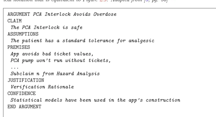
Once a hazard analysis has been performed, the resulting artifacts (e.g., worksheet, report, etc.) can be sent to various stakeholders for evaluation. Often, though, a hazard analy-sis is situated as part of a larger argument of the overall safety of a system, and though this argument can take various formats, arguments are typically presented in a structured format called an assurance case. Assurance cases typically contain, at a minimum, claims, arguments, and evidence, though Rushby explains in [36] that “standards and guidelines on which some certification processes are based often specify only the evidence to be pro-duced; the claims and argument are implicit, but presumably informed the deliberations that produced the guidelines.”
Assurance case notation, construction and evaluation are themselves well-studied, large subjects. While we will not go into great detail here, the interested reader is directed to [5] which is an excellent primer on the state-of-the-art.
PCA Interlock Safe PCA Interlock Avoids OD Verifica(on Ra(onale App avoids bad 9cket values Pump won’t run without 9ckets (Subclaim n from HA) Sta9s9cal model of popula9on’s analgesic tolerance Pa9ent tolerates analgesic …
Figure 2.8: An example of the Claims-Argument-Evidence assurance case format’s
graph-ical notation that is equivalent to Figure 2.9. Adapted from [5, pg. 56]
ARGUMENT PCA Interlock Avoids Overdose
CLAIM
The PCA Interlock is safe
ASSUMPTIONS
The patient has a standard tolerance for analgesic
PREMISES
App avoids bad ticket values,
PCA pump won’t run without tickets, ...
Subclaim n from Hazard Analysis
JUSTIFICATION
Verification Rationale
CONFIDENCE
Statistical models have been used in the app’s construction
END ARGUMENT
Figure 2.9: An example of the Claims-Argument-Evidence assurance case format’s textual
notation that is equivalent to Figure 2.8. Adapted from [5, pg. 56]
Notations
Rushby explains that there are two primary notations for assurance cases, with some degree of tool support for both the notations themselves and converting between the two [5].
Claims-Argument-Evidence (CAE) This notation, developed by Adelard, has both textual and graphical representations. An example from Rushby [5] that has been adapted for the PCA Interlock is shown graphically in Figure 2.8 and textually in Figure 2.9. The figures show some of the more common elements of assurance cases (claim, justification, etc.) as well as less common ones, like assumptions (or “side-warrants,”) and statements of confidence (or “backing,”) which Rushby explains are derived from Toulmin’s argument structure [37]. CAE has tool support from Adelard itself in the form of the Assurance and Safety Case Environment (ASCE) software.
Goal Structuring Notation (GSN) A second popular notation was introduced by Kelly and Weaver in [38] and then explained in great detail in Kelly’s doctoral dissertation [39]. A great example of this notation can be found in Figure 2 of Feng et al.’s fragment of a safety case for the PCA interlock scenario [40]. The primary elements here are goals (squares), strategies (parallelograms), contexts (stadiums), and solutions (circles). Helpfully, goals can be affixed with diamonds to denote that they are “undeveloped” and still need to be completed.
ISO/IEC 15026 In addition to academic sources, there is regulatory guidance on as-surance cases as well in the form of ISO/IEC 15026, which is titled Systems and Software
Engineering – Systems and Software Assurance. The standard has four parts:
1. Concepts and Vocabulary: This part clarifies the meanings of the terms as they are
used in the standard.
2. [The] Assurance Case: This explains the structure and content of an assurance case.
Note that unlike CAE and GSN, this standard uses a textual format.
3. System Integrity Levels: Since different systems have different levels of criticality,
they also should be evaluated to different levels of integrity. This part discusses the definition and use of levels of assurance integrity.
4. Assurance in the Life Cycle: This final part explains how assurance cases can be used throughout a product’s life cycle by aligning with the normatively-referenced IEEE 15288 and IEC 12207 (System and Software Life Cycle Processes, respectively) [41,42].
Evaluation
Evaluating an assurance case is no simple task. Not only is the system being evaluated large and complex except in all but the most trivial of cases, but also, as Rushby points out, an evaluator is also faced with evaluating the case itself [5]. That is, a great system may have a bad assurance case, or a bad system may have an excellent assurance case.
Worse still, many of the arguments in an assurance case are by nature subjective, so in addition to evaluating soundness, an evaluator is also tasked with evaluating confidence. Deciding how to explicitly include this confidence evaluation is an ongoing challenge, and initial attempts to model it statistically resulted in less-than-practicable solutions. An alter-native solution coming primarily from researchers at City University in London, results from the admission of the possibility of a system’s perfection and it has yielded more promising results—see for example [43, 44, 45].
2.2.5
Standardization Efforts
While the academic literature contains a great deal of knowledge regarding system safety, there is also a substantial amount of information, with which much of industry aligns, in various standards. Standards specific to particular portions of this effort are discussed throughout this chapter (i.e., IEEE 11073 in Section 2.1.4or AS 5506 in Section2.3.3), but we discuss and summarize a handful of relevant standards here.
General System Safety Standards
Though there are a number of standards specific to the (software-driven) medical device domain, there are two more general standards we discuss first in order to orient the reader
to the area and align with non-medical safety efforts.
IEC 61508 Perhaps the most relevant general system safety standard is IEC 61508, titled
Functional Safety of Electrical/Electronic/Programmable Electronic Safety-Related Systems
[46]. The seven-part standard discusses safety requirements for electrical, electronic, and/or programmable electronic (E/E/PE) systems throughout their lifecycle. The standard is divided into seven parts. Those parts provide both requirements (e.g., general requirements (part 1), requirements for E/E/PE safety-related systems (part 2), software requirements (part 3)) and guidance on meeting those requirements (e.g., examples of methods for the determination of safety integrity levels (part 5). It also provides standardized definitions and abbreviations (part 4), guidance on applying parts 2 and 3 of the standard (part 6), and an overview of techniques and measures (part 7)).
ARP 4761 A second notable standard is ARP 4761, titled Guidelines and Methods for
Conducting the Safety Assessment Process on Civil Airborne Systems and Equipment [47].
Though this standard applies to the construction of aircraft rather than generic systems or medical devices, it is valuable because it has been analyzed and referenced by a number of important authors in the safety literature, e.g., Leveson and Rushby [48, 5]. The process consists of three main analyses (explained in detail in the standard’s first three appendices) which are designed to roughly correspond to an aircraft’s primary development phases:
1. Functional Hazard Assessment (FHA): This analysis, which aligns with the
require-ments phase of an aircraft’s development, should “identify and classify the failure condition(s) associated with the aircraft functions and combinations of aircraft func-tions.” It “is a high level, qualitative assessment of the basic aircraft functions as defined at the beginning of aircraft development.”
2. Preliminary System Safety Assessment (PSSA): This analysis uses as input the output
![Figure 2.1: The ICE Architecture, figure adapted from [1, 2]](https://thumb-us.123doks.com/thumbv2/123dok_us/10971210.2985230/26.918.247.670.99.598/figure-ice-architecture-figure-adapted.webp)
![Figure 2.2: The MDCF Architecture, figure adapted from [1]](https://thumb-us.123doks.com/thumbv2/123dok_us/10971210.2985230/28.918.247.671.97.598/figure-mdcf-architecture-figure-adapted.webp)

![Figure 2.6: An example FTA for the PCA interlock scenario, adapted from [4]](https://thumb-us.123doks.com/thumbv2/123dok_us/10971210.2985230/38.918.251.672.99.412/figure-example-fta-pca-interlock-scenario-adapted.webp)

![Figure 2.15: Timing related errors in the EMV2 error type hierarchy, from [6]](https://thumb-us.123doks.com/thumbv2/123dok_us/10971210.2985230/70.918.104.815.103.249/figure-timing-related-errors-emv-error-type-hierarchy.webp)
