TR-0222-10-92-165
DARWIN: On the Incremental Migration of
Legacy Information Systems
1Michael L. Brodie Michael Stonebraker GTE Laboratories, Inc. College of Engineering
40 Sylvan Road University of California, Berkeley Waltham, MA 02254 Berkeley, CA 94720 March 1993 C I S L SE AI DB
1 This report is the result of the DARWIN project initiated by Michael Stonebraker in 1991. It is also available as a Technical Memorandum of Electronics Research Laboratory, College of Engineering, University of California, Berkeley.
This is an advanced version of a monograph to be published by Morgan Kaufmann Publishers in the first quarter of 1994.
Abstract
As is painfully evident today, the deterioration of the transportation, education2, and other national infrastructures negatively impacts many aspects of life, business, and our economy. This has resulted, in part, when responses to short term crises discourage investing in infrastructure enhancement and when there are no effective means for infrastructure evolution. This paper responds to the deterioration of the information system (IS) infrastructure that has strong negative impacts on ISs, on the organizations they support, and, ultimately, on the economy. This paper addresses the problem of legacy IS migration by methods that mediate between short term crises and long term goals. It presents an effective strategy and a spectrum of supporting methods for migrating legacy ISs into a target environment that includes rightsized hardware and modern technologies (i.e., infrastructure) such as a client-server architecture, DBMSs and CASE. We illustrate the methods with two migration case studies of multi-million dollar, mission critical legacy ISs. The contribution of this paper is a highly flexible set of migration methods that is tailorable to most legacy ISs and business contexts. The goal is to support continuous, iterative evolution. The critical success factor, and challenge in deployment, is to identify appropriate portions of the IS and the associated planning and management to achieve an incremental migration that is feasible with respect to the technical and business requirements. The paper concludes with a list of desirable migration tools for which basic research is required. The principles described in this paper can be used to design future ISs and an infrastructure that will support continuous IS evolution to avoid future legacy ISs.
2 The Edison project of Whittle Communications L.P., is attempting to create a innovative, for-profit alternative to the government funded school systems. It is based on the principle that Darwinian evolution applies not only to the species, but also to our institutions and organizations.
TABLE OF CONTENTS
1. MIGRATING LEGACY INFORMATION SYSTEMS ...1
1.1 Strategies ...2
1.2 Architectures ...4
1.3 Methods...7
2. MIGRATING DECOMPOSABLE LEGACY ISs ... 1 2 2.1 Forward Migration Method For Decomposable Legacy ISs... 12
2.2 Reverse Migration Method For Decomposable Legacy ISs ... 17
2.3 General Migration Method For Decomposable Legacy ISs... 19
3. CASE STUDY 1 MIGRATING CMS ... 2 4 3.1 CMS... 24
3.2 Analysis of the CMS Core... 25
3.3 The CMS Migration Plan ... 26
3.4 CMS Cut-over Issues ... 30
3.5 CMS Migration Summary ... 31
4. MIGRATING SEMI-DECOMPOSABLE LEGACY ISs... 3 2 4.1 Migration Method For Semi-decomposable Legacy ISs ... 32
5. CASE STUDY 2 MIGRATING TPS... 3 4 5.1 TPS... 34
5.2 TPS Analysis and Migration Challenges... 36
5.3 The TPS Migration Plan, Part I ... 38
6. MIGRATING NON-DECOMPOSABLE LEGACY ISs... 4 3 6.1 Migration Method For Non-decomposable Legacy ISs... 43
7. MIGRATING LEGACY ISs (GENERAL CASE)... 4 5 7.1 The TPS Migration Plan, Part II... 45
8. RESEARCH AGENDA ... 4 8 8.1 Gateways ... 48
8.2 Specification Extractor ... 48
8.3 Application Analyzer ... 48
8.4 Dependency Analyzer ... 49
8.5 Migration Schema Design and Development Tools... 49
8.6 Database Extractor... 49
8.7 Higher Level 4GL ... 49
8.8 Performance Tester... 50
8.9 Application Cut-over ... 50
8.10 Distributed IS Development and Migration Environment ... 50
8.11 Migration Planning and Management ... 50
8.12 Distributed Computing... 51
9. CONCLUSIONS AND EPILOGUE... 5 2 ACKNOWLEDGEMENTS... 5 4 REFERENCES... 5 5
1. MIGRATING LEGACY INFORMATION SYSTEMS
Most large organizations are deeply mired in their information systems (IS) sins of the past. Typically, their ISs are large (e.g., 107 lines of code), geriatric (e.g., more than 10 years old), written in COBOL, and use a legacy database service (e.g., IBM’s IMS or no database management system (DBMS) at all). These ISs are mission critical (i.e., essential to the organization’s business) and must be operational at all times. These characteristics define what we call legacy information systems (legacy IS). Today, legacy ISs pose one of the most serious problems for large organizations. Costs due to problems of a single legacy IS (e.g., failures, maintenance, inappropriate functionality, lack of documentation, poor performance) can often exceed hundreds of millions of dollars per year. They are not only inordinately expensive to maintain, but also inflexible (i.e., difficult to adapt to changing business needs), and brittle (i.e., easily broken when modified for any purpose). Perhaps worse is the widespread fear that legacy ISs will, one day, break beyond repair. Such fears combined with a lack of techniques or technology to fix legacy IS problems result in IS apoplexy. That is, legacy ISs consume 90% to 95% of all IS resources. This prevents organizations from moving to newer software, such as client-server configurations, current generation DBMSs, and fourth generation languages (4GLs). Consequently, organizations are prevented from rightsizing that involves moving from large mainframe computers to smaller, less expensive computers that fully meet current IS requirements. This apoplexy, in turn, is a key contributor to the software crisis. New requirements, often called the IS backlog, cannot be met since legacy ISs cannot be extended and new ISs cannot be developed with the 5% to 10% remaining resources. These problems are both key motivations of and major roadblocks to the world-wide movement to re-engineer corporations and their major ISs.
In legacy IS migration, an existing IS is evolved into a target IS by replacing the hardware and much of the software including the interfaces, applications, and databases. Under some circumstances, some existing components can, and should, be incorporated into the target environment. In this paper, the target environments are intended to take maximum advantage of the benefits of rightsized computers, a client-server architecture, and modern software such as relational DBMSs, 4GLs, and CASE. For example, a modern DBMS (e.g., backup, recovery, transaction support, increased data independence, performance improvements) assists in increasing control over the IS (e.g., maintenance). It also provides a basis for future evolution and integration with other ISs. For example, a DBMS could facilitate data liberation (i.e., any application could use the DBMS to access valuable corporate data that is currently inaccessible due to the legacy database service).
A fundamental goal of legacy IS migration is that the target IS not become a legacy IS. When the migration is complete, the target IS is fully operational in the target environment. All application code and user interfaces are completely written in a 4GL and the database resides on a current generation DBMS. A wise choice of target environment will facilitate the application being moved to a wide variety of current and future desktop machines and the database being deployed on a wide variety of computing platforms. Hence, the target IS can readily be ported to environments appropriate to current and future requirements. That is, the target IS is designed to be very flexible (e.g., portable) for current and future
rightsizing and to avoid becoming a future legacy IS.
In the rest of the introduction, we discuss migration strategies and select one, list migration objectives, and introduce the alternative migration architectures and methods that are presented in the paper.
1.1 Strategies
We now describe the motivating problems and the key to their solution in the context of two strategies for migrating legacy ISs, Cold Turkey and Chicken Little.
Cold Turkey involves rewriting a legacy IS from scratch to produce the target IS using
modern software techniques and hardware of the target environment. This strategy carries substantial risk of failure for the following reasons.
• A better system must be promised.
It is nearly impossible to propose a one-for-one rewrite of a complex IS. Management will rarely budget the required major expenditure if the only payoff is to lower future maintenance costs. Additional business functions must be promised. This adds complexity to the replacement IS and increases the risk of failure.
• Business conditions never stand still.
The development of large, complex ISs requires years to accomplish. While the legacy IS rewrite proceeds, the original legacy IS evolves in response to maintenance and urgent business requirements, and by midnight functions (i.e., features installed by programmers in their spare time). It is a significant problem to evolve the developing replacement IS in step with the evolving legacy IS.
More significant than maintenance and minor ad hoc changes are changes in the business processes that the IS is intended to support. These are typically in a constant state of flux. The prospect of incorporating support for new business processes in the replacement IS may lead to significant changes to the IS’s requirements throughout its development. This also increases the risk of failure.
• Specifications rarely exist.
The only documentation for legacy ISs is typically the code itself. The original implementors have long since departed. Documentation is often non-existent, out of date, or has been lost. The original specifications and coding practices are now considered primitive or bad (e.g., self-modifying code). For example, the code is often the only documentation for the commonplace variant record encodings in which the interpretation of one data element is controlled by another data element. Often, legacy code was written for high performance on some extinct computer, resulting in arcane code constructs.
In such situations, the exact function of the legacy IS must be decrypted from the code, if it is to be understood or copied in the replacement IS. This adds greatly to the complexity and cost of developing the replacement IS.
• Undocumented dependencies frequently exist.
Invariably, applications, from non-critical (e.g., reporting programs) to mission critical, access the legacy IS for its mission critical information and other resources. Over the ten plus year life of the legacy IS, the number of these dependent ISs grows (e.g., 1,200 in a case study described below), few of which may be known to the legacy IS owners. The process of rewriting legacy ISs from scratch must identify and accommodate these dependencies. This again adds to the complexity of the rewrite and raises the risk of failure of dependent ISs.
• Legacy ISs can be too big to cut-over.
Many legacy ISs must be operational almost 100% of the time. Many legacy databases or files require weeks to dump or download. Even if the rewritten IS were fully operational, there are no techniques to migrate the live data from the legacy IS to the new IS within the time that the business can support being without its mission critical IS. Live data must also be converted to fit the new system, again increasing project time and complexity. This may not just add complexity, it often prohibits Cold Turkey altogether.
• Management of large projects is hard.
The difficulty of most large projects is seriously under-estimated. Hence, there is a tendency for them to grow uncontrollably in head count. Few organizations are capable of managing the development of an IS with the several hundred contributors that are common for ISs of the size and complexity we are considering. Managing more and more people inevitably brings on the famous Brooks effect [BROO75] resulting in less and less useful work.
• Lateness is seldom tolerated.
Large projects are inevitably late due to the problems cited above. Management patience wears out quickly, especially in organizations whose basic function is not software production. This frequently results in the termination of partly or mostly completed projects.
• Large projects tend to bloat.
There is a tendency for large projects to become bloated with nonessential groups. For example, for a project as critical as a legacy IS migration, organizations may want to explore the introduction of new management techniques and technologies (e.g., Re-engineering, CASE). This is often done by adding additional groups to the already large project. Groups that are not critical to the migration itself increase the budget and management complexity, thus making the project more vulnerable to termination.
Cold Turkey involves high risk. It has been applied and has failed many times in large organizations. We now turn our attention to the alternative, low-risk and novel strategy,
Chicken Little, the focus and contribution of this paper.
Chicken Little involves migrating the legacy IS, in place, by small incremental steps
until the desired long term objective is reached. Each step requires a relatively small resource allocation (e.g., a few person years), a short time, and produces a specific, small result towards the desired goal. This is in sharp contrast to the vast resource requirements of a complete rewrite (e.g., hundreds of person years), a multi-year development, and one massive result. If a Chicken Little step fails, only the failed step must be repeated rather than the entire project. Since steps are designed to be relatively inexpensive, such incremental steps do not need to promise dramatic new function to get funded.
Each problem cited in Section 1.1 can be addressed in an incremental fashion. In addition, failures in individual steps may indicate large or previously unforeseen problems. Due to the incremental nature of Chicken Little, such problems can be addressed incrementally. Hence, Chicken Little is much safer and more feasible than Cold Turkey.
In this paper, we investigate and apply the Chicken Little migration strategy to legacy ISs, from well structured to unstructured. The key to successful Chicken Little migration, and
its principal challenge, concerns the selection of independent increments to migrate (i.e., portions of legacy interfaces, applications, and databases that can be migrated independently of each other), the sequencing of the increments to achieve the desired goal, and dealing with unavoidable problems (e.g., dependencies between migration steps).
1.2 Architectures
All ISs can be considered as having three functions: interfaces, applications, and a database service. The architectures of legacy ISs vary widely on a spectrum from well-structured (e.g., modular, hence decomposable) to unstructured3 (e.g., non-decomposable).
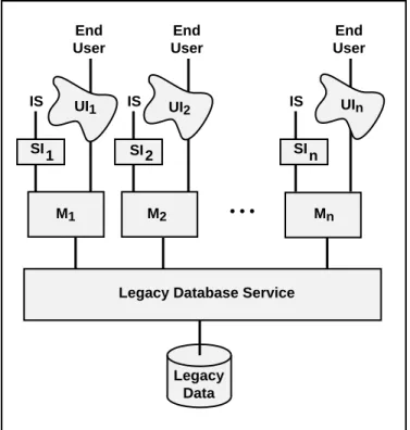
The best architecture for migration purposes is a decomposable structure in which the interface, application, and database services can be considered as distinct components with well-defined interfaces. Figure 1.1 illustrates a decomposable legacy IS that consists of a collection of application modules (Mi) each interacting with a database service and each, potentially, with its own user interface (UIj) and system level interface (SIj) through which it interacts with one or more IS. Interfaces, both user and system level, must be considered separately since they differ significantly in technology, design, performance requirements, and impact (e.g., number and requirements of human users versus ISs accessing the legacy IS). The prime requirements for an architecture to be decomposable are that the application modules are independent of each other (e.g., have no hierarchical structure) and interact only with the database service.
Legacy Data UI1
Legacy Database Service UI2 M1 M2 UIn Mn • • • SI SI SI 1 2 n IS End User IS End User IS End User
Figure 1.1: Decomposable Legacy IS Architecture
3 The reasons for a lack of structure are many. They relate to the state of the technology at the time of design, the design and development methods and tools, uncontrolled enhancements and maintenance, lack of documentation, and to many other aspects of ISs.
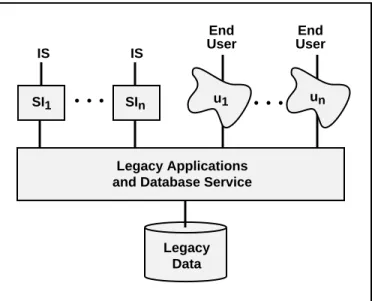
A worse architecture for migration purposes is a semi-decomposable legacy IS, illustrated in Figure 1.2. In comparison with a decomposable legacy IS, only user interfaces, UIi, and system interfaces, SIi, are separate modules. The applications and database service are not separable since their structure is more complex, not adequately engineered in accordance with current standards, or is poorly understood. The lack of desirable structure makes analysis and migration more complex and error prone.
• • • • • • IS End User Legacy Applications and Database Service
Legacy Data End User IS SI1 SIn u1 un
Figure 1.2: Semi-Decomposable Legacy IS Architecture
The worst architecture for migration is a non-decomposable legacy IS, illustrated in Figure 1.3. Such ISs are, from a system point of view, black boxes since no functional components are separable. End Users and ISs interact directly with one, apparently unstructured, legacy IS.
ISs End Users
Legacy Data
Legacy Interfaces, Applications, and Database Service
Figure 1.3: Non-Decomposable Legacy IS Architecture
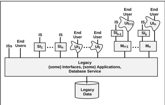
In general, the architecture of most legacy ISs may be neither strictly decomposable, semi-decomposable, nor non-decomposable. During its decade long evolution, a legacy IS may
have had parts added that fall into each architectural category resulting in a hybrid architecture, as illustrated in Figure 1.4. The figure is intended to suggest that some interface and application modules are inseparable from the legacy database service while others are modular and independent.
• • •
Legacy
(some) Interfaces, (some) Applications, Database Service ISs Legacy Data UI1 UIl End Users End User End User IS IS SI1 SIn UIl+1 UIn Ml+1 Mn SIl+1 IS End User IS End User • • • • • • SIn
Figure 1.4: Hybrid Legacy IS Architecture
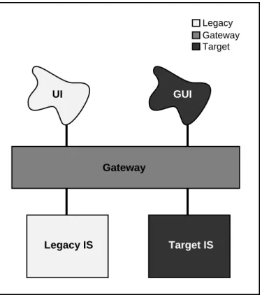
A Chicken Little legacy IS migration involves iteratively selecting and migrating parts of the legacy IS to become new parts of the iteratively constructed target IS. During the migration, the legacy IS and the target IS form a composite IS which collectively provides the mission critical IS function. In the composite IS, the legacy IS and target IS are connected by a gateway, as illustrated in Figure 1.5.
Gateways play the key role in the migration architectures described in this paper. By
gateway we mean a software module introduced between operational software
components to mediate between them. Given its controlling position, it can mediate many things (i.e., play many roles). One role is to insulate some components from changes being made to others. In Figure 1.5, the gateway makes any change to the legacy IS transparent to the legacy user interface (UI). That is, the gateway maintains the interface that the UI expects of the legacy IS even though the legacy IS is being changed “behind the scenes.” This transparency permits us to alter one part of the legacy IS at a time. This capability is critical to the Chicken Little strategy. As the target graphical user interface (GUI), in Figure 1.5, is iteratively introduced, the gateway makes transparent to the GUI and UI whether the legacy IS or target IS or both are supporting a particular function. Hence, the gateway can insulate a component that is not being changed (e.g., the UI) from changes that are being made (e.g., migrating the legacy database to the target database).
A second gateway function is to translate the requests and data between the mediated components (e.g., UI calls to target IS calls, target IS data to legacy UI formats). Gateways are widely used for the two purposes stated above. Few if any gateways provide the third, critical function of coordination between the mediated components. For example, coordination for update consistency may be required for an update request that the gateway
directs to the legacy IS and to the target IS. In the migration methods presented, we specifically define this critical coordination function of gateways.
Legacy Gateway Target Gateway GUI UI Legacy IS Target IS
Figure 1.5: IS Migration Architecture
The placement of the gateway is a critical factor that affects the complexity (or simplicity) of the migration architecture, the gateway, and the migration method. In the best case, the decomposable legacy IS, the gateway can be placed between the application modules (Mj) and the legacy database service, illustrated on the right hand side of Figure 1.6 (for simplicity, target ISs are not shown). In this case, we call it a database gateway since it encapsulates the entire database service and database from the perspective of the application modules. For the semi-decomposable legacy IS, the lowest the gateway can be placed is between the interfaces and the rest of the legacy IS (i.e., applications, database service, and database), illustrated in the center of Figure 1.6 (and in Figure 1.5). It is called an
application gateway since it encapsulates from the applications down, from the
perspective of the interfaces. Due to the functionality it encapsulates, an application gateway can be considerably more complex than a database gateway. In general, the higher up in the architecture the gateway is placed, the more functionality it encapsulates and the greater the complexity of the gateway. Finally, an IS gateway encapsulates the entire legacy IS in the case of the non-decomposable legacy IS. Hence, it is the most complex.
1.3 Methods
A migration method consists of a number of migration steps that together achieve the desired migration. A step is responsible for specific aspects of the migration (e.g., database, application, interface). Each legacy IS and its operational context, both business and technical, pose unique and frequently mutually inconsistent, migration requirements that, in turn, require a unique migration method. The migration methods presented in this
paper are tailorable to address these requirements, which include the following: • Migrate in place.
• Ensure continuous, safe, reliable, robust, ready access to mission critical functions and information at performance levels adequate to support the business’s workload. • Make as many fixes, improvements, and enhancements as is reasonable, to address
current and anticipated requirements.
• Make as few change as possible to reduce migration complexity and risk. • Alter the legacy code as little as possible to minimize risk.
• Establish as much flexibility as possible to facilitate future evolution.
• Minimize the potential negative impacts of change, including those on users, applications, databases, and, particulalrly, on the on-going operation of the mission critical IS.
• Maximize the benefits of modern technology and methods.
Legacy Interfaces, Applications, Database Service Legacy Data • • • ISs UI1 UIl End Users End User End User IS IS SI1 SIn UIl+1 UIn Ml+1 Mn SI l+1 IS End User IS End User • • • • • • SIn
Application Gateway Database Gateway
IS Gateway
Figure 1.6: Gateway Types and Placements
The iterative nature of the Chicken Little strategy leads to two ways to reduce risk. First, there must always be a fail safe fall back position, should any incremental step fail.
Second, the increment size must be chosen to make the risk of the current step effectively zero. We offer no new ways of evaluating such risks but we do emphasize the importance of risk evaluation and avoidance.
The greater the independence of the steps, the greater the flexibility for adapting a migration method to specific migration requirements, changing requirements, and mistakes. Independent steps can proceed independently (e.g., in any order). Gateways are one of the primary means of providing independence between steps, since they can encapsulate system components that are undergoing change behind an unchanging interface.
This paper presents a set of migration methods that apply to all legacy ISs. Each method consists of five basic steps:
• Iteratively migrate the computing environment. • Iteratively migrate the legacy applications. • Iteratively migrate the legacy data.
• Iteratively migrate the user and system interfaces.
• Iteratively cut-over from the legacy to the target components.
Migrating the computing environment, the applications, and the database are obvious steps. The final two steps are less obvious and require some explanation.
Interface Migration and Gateways
First, let’s consider interface migration. Legacy ISs are, by definition, mission critical. They contain key corporate resources. The user and system interfaces control all uses of the system and all access to those resources. Hence, IS interfaces are as critical as the databases and the applications. Errors that originate in the interfaces can significantly negatively affect the viability of the content and performance of an IS and of all the ISs and people that interact with it. Generally, user interfaces significantly affect the working environment and productivity of a large number of people (e.g., bank or telephone service order clerks). The system interfaces significantly influence the efficiency of all current and future ISs that interact with the target IS. Interfaces are critical before, during, and after the legacy IS migration. Indeed, the success of the migration depends critically on the interfaces to the composite IS that exists during the migration. Hence, interface migration should be considered equally with database and applications migration. This makes sense technically, since interfaces, databases, and applications have distinct technical challenges and supporting technologies.4 Interface migration can be used to implement corporate-wide interface improvements (e.g., TTY to GUI) and standardization that is currently being pursued in most IS organizations. Interface migration can provide a basis for, and many of the benefits of, IS integration and interoperability before their being provided at the database and applications level.
4 The separation of interface, database, and application issues and technologies is part of a trend towards next generation information systems technologies, architectures, and methods. The trend is to separate as many aspects as possible to achieve, amongst other goals, greater modularity, flexibility, reusability, portability. This is widely discussed in terms of Enterprise Information Architectures and middleware [BROD92a].
During migration, legacy IS modules and their interfaces can be operational simultaneously with the corresponding target IS modules and their interfaces. This may require that the desktop machine (e.g., PC) of the target environment emulate a dumb terminal interface. For IBM legacy code, the PC must include 3270 emulation, a widely available feature. As a result, The user interface could get ugly during the migration with GUI windows existing simultaneously with 3270 windows on the PC. These problems can be addressed by an interface gateway (i.e., a single user interface that can help to simplify the multiple interfaces of the composite IS). It can also hide the fact that the functions are being supported by the legacy IS, the new IS, or both. This helps to insulate IS users from changes in the user interface as well as IS changes. The interface gateway permits the changes to be phased in at a rate appropriate to the user community. Interface gateways can also be used to introduce, temporarily, functionality and extensions intended for the target IS but added earlier to gain some benefits (e.g., essential edit checks not in the legacy interfaces and not yet available in the target interfaces). This adds alternatives hence flexibility to the migration methods.
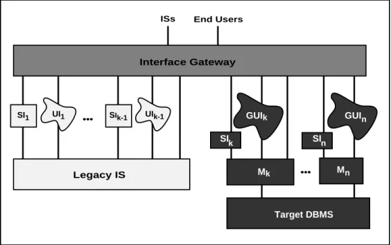
A key to a successful interface migration is the interface gateway. It insulates all end users and interfacing systems from any negative effects of the migration, as illustrated in Figure 1.7. An interface gateway captures user and system interface calls to some applications and then translates and re-directs them to other applications. It also accepts the corresponding application responses and translates, integrates and re-directs them to the calling interface. For some legacy interfaces, this means capturing TTY keystrokes and mapping them into GUI interfaces or directly to applications. An interface gateway provides more independence between the interfaces and the applications thus adding to the flexibility of the corresponding migration methods. Besides gateway functionality, it could provide a complete user interface development and management environment. It might also support migration with versioning and other functionality. Finally, as suggested in Section 9, the interface gateway can be maintained as part of the target IS architecture to support future interface migration and evolution.
GUIk GUI Mk M Target DBMS SIn SIk n n UI1 SI1 SIk-1 UIk-1 Interface Gateway ISs End Users
Legacy IS •••
•••
Cut-Over
We end this subsection by considering cut-over. We use the term cut-over to refer to the process of switching from the legacy IS to the target IS. For example, whereas the application migration step is used to design, build, and install target applications, the cut-over step is used to iteratively cut-cut-over operations from the legacy applications to the target applications, application by application, site by site, and user by user according to specific requirements.
Although there could be a cut-over phase for each of the above four steps, the size and complexity of the ISs we are considering can warrant a separate cut-over step. In large organizations, such as banks and telecommunications companies, IS cut-over may involve hundreds of sites, hundreds of users, and hundreds of versions of legacy and target database, application, and interface modules. Target modules may be ready months or years before the target environment is in place or before all end users are prepared for the change. The cut-over step involves coordinating all these components so that the composite IS continues to meet the mission critical IS requirements. This complexity alone can warrant a separate cut-over step. The size of the cut-over step may require that it be iterative (i.e., done in appropriately sized chunks), consistent with the Chicken Little strategy. It can also be optimal to proceed with all steps in parallel. For example, some hardware and some software in some sites can be cut-over for some users while the corresponding legacy components are still in operation. Iterative and parallel cut-over increases the flexibility of the methods but also increases the complexity of the cut-over procedure, further motivating cut-over as a separate step.
A significant challenge for most migration methods is to plan, manage, and modify, as needed, the steps and their interactions. A related challenge is to achieve a migration plan that is adequately coordinated to iterate and parallelize the migration steps. The methods presented in this paper are intended to provide this flexibility so that they can be tailored to the requirements and available resources.
In Section 2, we develop and present the simplest method that applies to decomposable legacy ISs. We illustrate this method in Section 3, with a case study for a legacy banking system from a major bank. For legacy ISs with more complex requirements and architectures (e.g., semi-decomposable, non-decomposable, general case), we extend the simple method in subsequent sections. We also add details that could have been included earlier but were deferred to simplify the initial descriptions. In Section 4, we extend the method to semi-decomposable legacy ISs and illustrate it, in Section 5, by a case study for a legacy telecommunications facilities management system from a large telephone company. In Section 6, we further extend the method to non-decomposable legacy ISs. Finally, in Section 7, we present the migration method for the general case.
The legacy ISs presented in the case studies are typical of hundreds of such ISs known to the authors. They provide excellent examples of legacy IS migration problems and challenges. Although legacy IS re-engineering and migration are frequently discussed, there are few, if any, effective migration methods, tools, or techniques. In this regard, we list, in Section 8, desirable tools and needed research that would facilitate the application of Chicken Little to real legacy ISs. We conclude the paper with summary comments and an epilogue on the status of the case studies.
2. MIGRATING DECOMPOSABLE LEGACY ISs
In this section, we present a Chicken Little method for migrating legacy ISs that are decomposable, or that can be restructured accordingly. Our goal is a target IS that is decomposable and is in our target environment (e.g., rightsized computers, a client-server architecture, modern software). Decomposability in the target IS is intended to facilitate future change to avoid future legacy IS problems.
The method for migrating decomposable legacy ISs involves a forward migration method, described in Section 2.1, and a backward migration method, described in Section 2.2. On their own, the forward and backward migration methods are not widely applicable. However, they are fundamental to the migration methods presented in the rest of the paper.
2.1 Forward Migration Method For Decomposable Legacy ISs
This sub-section presents the method for migrating decomposable legacy ISs for which the database can be migrated in one initial, Cold Turkey step. It involves a forward database
gateway. This facilitates a Chicken Little migration of the applications and their interfaces
after the Cold Turkey database migration. It is called a forward migration since it migrates
unchanged legacy applications forward onto a modern DBMS and then migrates the applications. As discussed below, a Cold Turkey database migration and other limitations may render the forward migration method inappropriate for most migrations.
Step F(orward)1 Iteratively install the target environment.
Identify the requirements for the target environment based on the total target IS requirements. Select and test the environment. Install the environment including a desktop computer for each target IS user (e.g., bank clerk, telephone service order clerk) and appropriate server machines. This requires replacing a dumb terminal with a PC or workstation and connecting them with a local area network. Such a move to desktop, client-server computing is currently being studied in most IS shops and is being implemented in many. This facilitates the construction of GUI programs, necessary in subsequent steps, and off-loading code from a server machine, where MIPS are typically expensive, to a client machine, where MIPS are essentially free.
Step F1 involves significant changes in (i) hardware and software, (ii) applications, development, and maintenance architectures, and (iii) users and management. These changes may require significant investments and time. Hence, Step F1 may prolong the entire migration. Following the premise underlying Chicken Little of migrating in small, iterative steps, Step F1 can begin at any time and can be taken in steps appropriate to the context. That is, install a few PCs at a time and deploy new software at a rate appropriate to the context.
Step F2 Analyze the legacy IS.
Understand the legacy IS in detail. This corresponds to writing requirements for the legacy IS and for the target IS. Sources for the understanding include documentation, if any exists, the code5, and knowledge of the system and its use from people who support, manage, and use the legacy IS. The tendency to include new target IS requirements must be
5 Existing tools can assist with this step (e.g., Reasoning Systems’ Refine and Bachman Information Systems’ The Analyst for code analysis.
managed due to the consequent increase in complexity and risk of failure.
Step F3 Decompose the legacy IS.
Modify the legacy IS to ensure that it is decomposable. Dependencies between modules, such as procedure calls, must be removed. There must be well-defined interfaces between the modules and the database services. The cost of this step depends on the current structure of the legacy IS. If such a restructuring is not possible, other migration methods may apply.
Step F4 Design the target applications and interfaces.
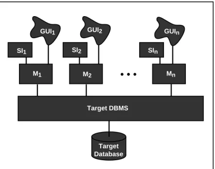
Design and specify the target IS. This requires designing the software architecture of the target IS, illustrated in Figure 2.1. It includes a modern DBMS and target database that can be centralized, on one server machine, or distributed over the multiple servers in a client-server architecture. It also includes application modules (Mi) each with its corresponding user interface (GUIi) and, possibly, system interface (SIi). Design target GUIs and SIs and an interface migration strategy including the decision whether to build an interface gateway. The target modules and interfaces will run on the client machines in the target environment. Following the principle that significant functionality not be added during the migration, legacy and target application module functions are intentionally similar.
Target Database GUI1 Target DBMS GUI2 M1 M2 GUIn Mn
• • •
SI1 SI2 SInFigure 2.1: Target IS Architecture
Step F5 Design the target database.
Design a relational6 schema to meet the data requirements of the target IS. This requires an understanding of the target and legacy ISs and uses the results of the previous steps. Depending on the legacy code and the application requirements, the target database design
step can be very complex. Legacy IS development techniques can make data definitions and structures difficult to find and understand. Before the age of databases, the distinction between data and application code was often blurred. It was also common to distribute data definitions throughout the application7. The complexity of this step can be large enough to warrant iterating in small increments, as discussed in Section 2.3. Re-engineering tools8 can be used to extract data definitions from legacy code, to design schema fragments for each increment, and to integrate the schema fragment into a single schema.
Due to the critical role of data in any IS, this step provides benefits whether or not the legacy IS migration proceeds (e.g., a deeper understanding of the IS).
Step F6 Create and install the forward database gateway.
Develop the forward database gateway. The gateway is intended to encapsulate the target DBMS and target database from the legacy applications and to permit the application and database migration steps to proceed independently. The forward gateway is designed so that the legacy applications need not be altered in any way. It includes a translator that captures and converts all legacy database service calls from legacy applications on the mainframe into calls against the modern DBMS on the server machine(s). The conversion may require a complex mapping of the calls (e.g., one to many, many to many, special purpose procedures), and data translation. The gateway must also capture responses from the DBMS, possibly convert them, and direct the result to the appropriate module(s). The gateway can also be used to enhance or correct legacy applications immediately rather than waiting for the application migration step. For example, the data and call translator can introduce new data formats, data edits, and integrity and error checking and correction that will later be done in target applications.
The forward database gateway evolves as the IS migration proceeds. As target applications are cut-over and legacy applications are retired, the gateway’s translation and redirection functions are reduced accordingly. To support the mapping and redirection functions, it may be useful to implement mapping tables. Mapping tables are tables or directories that provide a mapping between legacy database service calls and their modern DBMS counterpart(s) as well as between legacy data items and their corresponding target data counterpart(s). The tables can identify when complex mappings (e.g., mapping programs) are required.
Constructing a forward gateway can be very costly. It involves writing the gateway from scratch or tailoring a commercial gateway product9 to meet the migration requirements. For certain DBMSs, a general purpose forward database gateway can be built. In some cases, constructing a forward database gateway can be very complex due to the low-level legacy database service calls which may have semantics that are unimplementable in SQL. See [DATE87] for a discussion of this point in the context of IMS to SQL conversion. Such cases require a special purpose gateway that handles calls on a case-by-case basis.
7 There is currently a trend back to these ideas. Object-oriented and distributed computing principles suggest moving from a single, centralized database schema to distributed class definitions that encapsulate data and functions.
8 For example, Bachman Information Systems’ Re-Engineering Product Set.
9 Some DBMS vendors provide forward database gateway functions, other vendors specialize in them. For example, Computer Associates’ Transparency Software is intended to provide translation of native or legacy DBMS calls to IMS, VSAM, and DB2 to calls to their CA-Datacom DBMS.
The gateway must be installed in the legacy IS architecture between the application modules and the legacy database service in preparation for the database migration (Step F7). A gateway can significantly impact IS performance. It must be carefully designed and thoroughly tested keeping in mind that the composite IS (the legacy IS plus the target IS) is mission critical and can never fail.
If a forward database gateway is impractical, alternative methods, discussed in subsequent sections, may be applicable.
Step F7 Migrate the legacy database.
Force-fit the legacy application modules to the target database to achieve the architecture
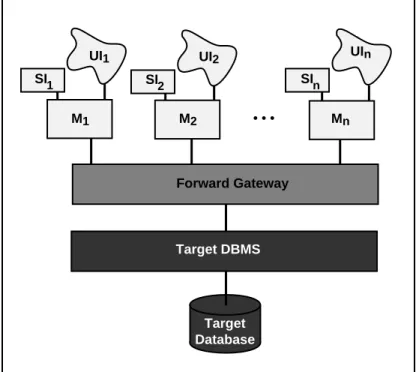
illustrated in Figure 2.2. This involves installing the target DBMS on the server machine(s), implementing the schema resulting from Step F5, migrating the legacy database to the target DBMS under the new schema, and using the gateway to support the legacy application calls. Database migration involves downloading, converting, and uploading, possibly large amounts of data. Products10 support some of these functions. The forward database gateway may be useful in the database migration as it contains relevant mapping and translation information.
Target Database UI1 Forward Gateway UI2 UIn M1 M2 • • • Mn Target DBMS SI 1 SI2 SIn
Figure 2.2: Forward Migration Architecture, Initial State
Cold Turkey database migrations may be impractical for several reasons. The legacy database may be so large or complex that there is no effective one-step, Cold Turkey migration method. Even if a method exists, some databases are so large that the time required for migration is greater than that allowable for the system to be non-operational. Such cases may require an iterative database migration method, as described in subsequent
sections.
Step F8 Iteratively migrate the legacy applications.
Select and migrate legacy modules, one (or more) at a time. Selection should be based on technical (e.g., simplicity) and organizational (e.g., cost, importance) criteria. This involves rewriting the legacy module(s)11 (M
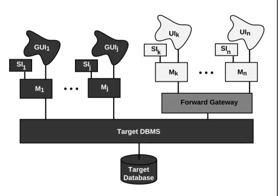
i) to run directly against the modern DBMS, as illustrated in Figure 2.3 for modules M1 through Mj.
The target applications will run on a client machine in the target environment. They can be used to replace the legacy application modules that run on dumb terminals. The remaining legacy modules (Mk through Mn in Figure 2.3) must continue to be used.
Target Database GUI1 Forward Gateway GUIj UIk UIn M1 Mj Mk • • • Mn Target DBMS SIn SIk SIj SI1 • • •
Figure 2.3: Forward Application Migration Architecture, Intermediate State
Step F9 Iteratively migrate the legacy interfaces.
Select and migrate legacy interfaces, one (or more) at a time. Selection should be based on principles similar to those in Step F8. If a 4GL is used which supports application and interface development, interface and application migration might be coordinated. This involves rewriting the legacy user (UIi) and system interfaces (SIi) to run directly against the modern DBMS. The target interfaces will run on a client machine in a 4GL/GUI environment on the desktop. They can be used to replace the legacy interfaces that run on dumb terminals. The remaining legacy interfaces (Uk and SIk through Un and SIn in Figure 2.3) must continue to be used. An interface gateway could be used here to support
1 1 There is a growing number of products to assist with rewriting legacy code into target applications. For example, Seer Technologies Inc.’s High Productivity System assists in converting IMS applications to SQL.
interface migration.
Step F10 Iteratively cut-over the target IS.
Cutting-over the new IS involves cutting-over operations to the forward gateway, and the migrated target database, applications, and interfaces on client-server machines, and then discarding the legacy components. When the last module is cut-over and no legacy modules are in use, the forward database gateway can be discarded. However, since change is constant and the migration process may take a long time, the gateway may serve future migration and evolution requirements, as discussed in Section 9. Finally, the costly legacy environment, including the mainframe and the dumb terminals, can be discarded. The resulting target IS is illustrated in Figure 2.1.
The cut-over can begin as soon as the database is migrated. It continues as applications are migrated and can be extended indefinitely. For example, it may be economical to run a bank branch or telephone office on the legacy IS for a year after others have migrated if they are to be shut down thus losing the migration investment. Using the forward database gateway, legacy IS modules and their interfaces can be operational simultaneously with the corresponding target IS modules and their interfaces as long as required.
The flexibility, hence applicability, of a migration method increases as the steps become iterative and parallel. In the forward migration method, only four steps (i.e., F1, F8, F9, and F10) were described as iterative, partly to simplify the explanation. More steps could and should be iterative. For example, the database migration step could be made iterative. However, this will complicate the cut-over as well as the gateway that would have to mediate between the diminishing legacy database and the growing target database. In subsequent migration methods in this paper, all steps become iterative.
2.2 Reverse Migration Method For Decomposable Legacy ISs
This sub-section presents the method for migrating decomposable legacy ISs for which the database can be migrated in one final, Cold Turkey step. It involves a reverse database
gateway that facilitates a Chicken Little migration of the applications and their interfaces
before the Cold Turkey database migration. It is called a reverse migration since it migrates
target applications in the reverse direction, back onto the legacy database until it is subsequently migrated. This method permits more time to deal with the database migration. As with the forward migration, a Cold Turkey database migration and other limitations render the reverse migration method of limited applicability. Reverse migration principles are important as they are included in all subsequent migration methods.
In the reverse migration method is similar in most steps to the forward method. We focus here on only those steps that differ.
Step R(everse)1 Iteratively install the target environment. (See Step F1) Step R2 Analyze the legacy IS. (See Step F2)
Step R3 Decompose the legacy IS. (See Step F3)
Step R4 Design the target applications and interfaces. (See Step F4)
Step R6 Create and install the reverse database gateway.
Develop the reverse database gateway. The reverse database gateway includes a translator that captures and converts all calls to the modern DBMS from target applications and maps them into calls to the legacy database service. It must also capture, translate, and direct responses from the legacy database service to the appropriate modules.
The functions of and challenges in developing a reverse gateway are similar to those of the forward gateway (e.g., potentially complex mappings). As the IS migration proceeds, the reverse gateway must be evolved. Initially, it may support one target application module. Iteratively, it supports more target application modules until all are supported, thereby completely encapsulating the legacy database service. It contracts as the target applications are migrated to access the target database directly.
As with the forward database gateway, the reverse database gateway may require mapping tables or directories, data and call conversion, and can have its functionality extended. Also, there are many alternatives for constructing a reverse database gateway (e.g., hand-code functions as needed, build a general purpose reverse database gateway, adapt commercial products). Hand coded reverse database gateways may be appropriate for small IS migrations. However, a general purpose reverse database gateway may be more appropriate for large IS migrations. Some products provide reverse database gateway functions12. These products do not support data integrity, transactions (i.e., updates), or query optimization. They also require that the calling applications be aware that they are calling a gateway and not a DBMS directly. This will require changes to all target applications once the gateway is removed.
The reverse database gateway must be installed in the migration architecture between the target application modules and the legacy database service, as illustrated in Figure 2.4. It then becomes a vital component in the migration and operation of the mission critical IS.
Step R7 Iteratively migrate the legacy applications. (See Step F8)
Using the reverse gateway, map the target application modules onto the legacy database to achieve the architecture illustrated in Figure 2.4. Select and migrate legacy modules one (or more) at a time. This step is similar to Step F8 in the forward migration method except that, initially, target application modules run against the reverse gateway.
The target applications will run on a client machine in the target environment on the desktop. They can be used to replace the legacy application modules. The remaining legacy modules (Mk through Mn in Figure 2.4) must continue to be used until they too are migrated.
Step R8 Iteratively migrate the legacy interfaces. (See Step F9)
1 2 Some DBMS vendors provide reverse gateway functions, other vendors specialize in them. For example, SQL Solutions’ RMS Gateway product provides translation between DEC’s RMS (files) and various RDBSMs. Oracle’s SQL*Net and SQL*Connect provide translation from SQL to DB2, SQL/DS, RMS (files), and IMS. Information Builders Inc.’s Enterprise Data Access (EDA) provides translation between more than 50 DBMSs and file systems in client-server environments. Cross Access Corp.’s Cross Access product provides similar translation between more than 15 DBMSs and file systems.Apertus Technologies’ Enterpise/Access product will povide reverse gateway services.
Step R9 Migrate the legacy database. (See Step F7)
Step R10 Iteratively cut-over the target IS. (See Step F10)
This step is similar to the forward migration Step F10 except that the reverse migration cut-over is more constrained and, consequently, of higher risk. The forward migration architecture can simultaneously support legacy and target applications. This provides flexibility as to how and when to cut-over the IS. In the reverse migration method, once the legacy database is migrated, the legacy applications can no longer be used. Hence, the database, applications, and interface cut-overs must be coordinated and must conclude simultaneously. This may place severe constraints on the cut-over since the IS is mission critical and can be non-operational for only a very short time.
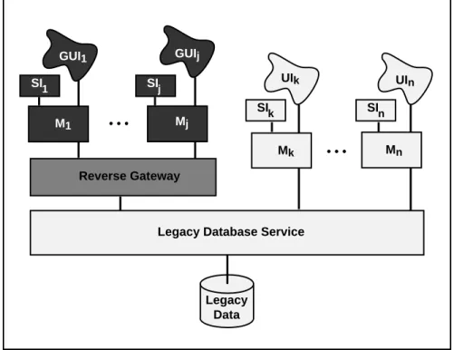
Legacy Data GUIj GUI1 UIk UIn Mn Mk Mj M1 Reverse Gateway • • •
Legacy Database Service
SIn SIk
SIj SI1
• • •
Figure 2.4: Reverse Migration Architecture, Intermediate State
2.3 General Migration Method For Decomposable Legacy ISs
This sub-section presents a migration method for all decomposable legacy ISs. It uses a reverse database gateway and a forward database gateway, which permits all migration steps to be iterative and parallel. Following our Chicken Little strategy, IS migration can proceed by selecting, as iteration increments, any appropriate subset of IS functions and corresponding data (or vice versa).
For simplicity, we describe only the key differences with the forward and reverse migration methods already described. These include, the gateway (Step D6), and the database, application, and interface migration steps (Steps D7, D8, and D9). Making Steps D2 through D5 iterative is a challenge left to the reader, as is their coordination in the cut-over, Step D10.
Step D(ecomposable)1 Iteratively install the target environment. (See Step R1) Step D2 Iteratively analyze the legacy IS. (See Step R2)
Step D3 Iteratively decompose the legacy IS. (See Step R3)
Step D4 Iteratively design the target applications and interfaces. (See Step R4)
Step D5 Iteratively design the target database. (See Step R5)
Logically partition the legacy database to facilitate iterative database migration. Identify subsets of the legacy database that are sufficiently separable to be migrated independently to the target database. For each subset, design the target database schema (i.e., apply Step R5) so that the subset can be integrated into the target database.
Step D6 Iteratively create and install the database gateway. (See Steps F6 and R6) Unlike the reverse and forward methods, this migration may require simultaneously supporting portions of the corresponding legacy and target applications and databases. During the migration, the operational mission critical IS will be some composite of legacy and target ISs, as illustrated in Figure 2.5. The gateway must support this composite. For example, it must ensure that a degree of update integrity be maintained on any part of the legacy database that is replicated in the target database. For example, if a data item in the legacy database is updated, the corresponding target data item may be required to be updated accordingly within a given time. Such correspondences must be identified, expressed in inter-database dependencies (e.g., conditions under which legacy database updates must be reflected in the target database, and vice versa), and maintained by the gateway. This coordination role of the gateway is similar to the transaction management role of a DBMS.
This step is iterative in that the gateway functions vary throughout the migration. At the beginning of the migration, when the target database is empty, and at the end, when the legacy database is empty, there is little for the gateway to do. When there are many legacy and target components operating simultaneously, the gateway must maintain all the inter-database dependencies. Failure to do so at all or within adequate performance bounds may cause the mission critical, composite IS to fail.
The gateway consists of at least four components: the forward database gateway, the reverse database gateway, a mapping table, and a coordinator. Since the potential mappings are more complex than in the forward and reverse database gateways, mapping tables will be correspondingly more sophisticated. It may be useful to maintain other descriptive data to assist with the migration. This meta-data may form a small migration database that could be supported by the target DBMS. If the database mappings are sufficiently complex, the migration database may contain a schema that integrates those of the legacy and target databases, as is done in distributed DBMSs [OZSU91]. Indeed, the gateway bears strong similarity to a general purpose distributed DBMS.
The coordinator manages all gateway functions. On the basis of the location of the data being accessed and on the relevant inter-database dependencies, all given in the migration database, the coordinator must map calls from the legacy and target applications to one or more of the legacy database, the target database, the reverse gateway or the forward gateway. The alternatives are illustrated in Figure 2.5. Calls from legacy modules Mk through Mn can be directed to the legacy database service, without translation, and to the target DBMS via the forward database gateway. Calls from target modules M1 through Mj
can be directed to the legacy database service via the reverse database gateway and to the target DBMS, without translation. The gateway may also need to combine responses from both database services and map them to either or both legacy and target applications. The most challenging requirement for the coordinator is to ensure the inter-database dependencies for updates as well as for queries mixed with the updates. This may require a two-phase commit (2PC) protocol [SKEE82] to be used by both the legacy and target DBMSs and by the gateway coordinator, as is done in distributed DBMSs [ELMA92, OZSU91]. Target Database Legacy Data Mapping Table Reverse Gateway Forward Gateway Coordinator
Legacy Database Service Target DBMS
G a t e w a y GUI1 GUIj UIk UIn M1 • • • Mj Mk Mn SIn SIk SI j SI1 • • • D a t a b a s e
Figure 2.5: Decomposable Legacy IS Migration Architecture
In an IBM environment, CICS can perform the coordinator role and both DB2 and IMS support 2PC; hence distributed transactions are easily supported. However, most legacy database services do not support 2PC. To guarantee that the inter-database dependencies are maintained, 2PC can be hand coded into the application modules. This exotic and difficult work-around is described in [BREI90]. Alternatively, the user can decompose a distributed transaction into two transactions, each updating only one database. If either transaction fails to commit, application logic can perform a compensating transaction to return the database to a consistent state. Compensating transactions are discussed in [GARC87, WACH92]. Another alternative that alleviates the application programmers from such concerns is to develop distributed transaction support in the coordinator, based on existing and special purpose components (e.g., build the coordinator on the target DBMS that might also support distributed transactions). Besides providing 2PC protocols and distributed transaction management, the legacy database service must also be augmented with other transaction support including transaction commit and abort, rollback,
and compensation. This will be one of the most complex technical challenges in the migration and should be left to expert DBMS developers. It is this coordinator function that current gateway products do not support. Although costly and risky, the benefits of building a coordinator may be more considerable than might initially be thought. The longer the gateway is used, the greater the benefits of implementing distributed transactions support, since it is amortized over a longer productive period. Later in this paper, we suggest that IS migration will become a way of life. Hence, distributed, flexible transaction support, as described above, will become a critical component of the target environment. No such products exist.
Step D7 Iteratively migrate the legacy database. (See Step R9)
Select one (or more) independent legacy database subsets (identified in Step D5), based on technical and organizational criteria. Implement the corresponding schema in the target DBMS (e.g., by iteratively augmenting the current target schema). Migrate the corresponding legacy database subset to the target DBMS. This might be aided with several potential migration or downloading tools (e.g., in the legacy database service, in the target DBMS, or special purpose products). The gateway could be extended to support database migration since the migration database could contain the relevant meta-data for translation. The gateway must be enhanced to accommodate any new inter-database dependencies that may have arisen from the migration of the current database subset.
Database migration can use the following simple method. When the migration of some subset of the database is attempted, there are K old modules and N - K new ones . The new applications use a reverse gateway to convert as needed from SQL to the legacy database service. The old applications use the forward gateway when needed to talk to the SQL DBMS. Now, introduce a target distributed DBMS that supports fragments for database tables. Hence, each table can be distributed, and a distribution criteria determines where individual records reside. For example, the following distribution criteria places young employees on machine 1 and old employees on machine 2.
distribute EMP to machine-1 where EMP.age < 30 to machine-2 where EMP.age >= 30
Further suppose the distributed DBMS supports distributed transactions through 2PC. Lastly, most distributed DBMSs allow data to be stored in tables managed by other vendor's single-site DBMSs. This is accomplished by an SQL reverse gateway within the distributed DBMS that translates from SQL to the foreign vendor’s protocol.
Such software makes migration a breeze. Bring up the distributed DBMS with the initial distribution criteria:
• old system: everything • new system: nothing
Legacy IS transactions are supported by converting legacy database accesses to SQL accesses that are processed by the distributed DBMS. If necessary, the distributed DBMS can route accesses to data not yet migrated through the reverse gateway to the old DBMS. Over time the migration is accomplished by changing the distribution criteria in small increments until it is finally:
• old system: nothing • new system: everything
The cut-over Step D10 must be invoked to support the related database cut-over that brings the migrated database into operational use.
Step D8 Iteratively migrate the legacy applications. (See Step R7)
Select and migrate legacy modules one (or more) at a time similar to Step R7. A target module will run against the gateway until the gateway is no longer required (e.g., the corresponding target database has been migrated and no coordination is required). Then, the target module can be migrated from the gateway to the target DBMS.
Step D9 Iteratively migrate the legacy interfaces. (See Step R8)
Step D10 Iteratively cut-over the target IS. (See Step R10)
Coordinate all the iterative, and possibly parallel, migrations of subsets of the legacy IS (e.g., environment, database, applications, and interfaces) making them operational while ensuring that the composite IS meets its mission critical requirements. This step is similar in nature to the corresponding forward and reverse migration steps, Steps F10 and R10. This step offers a wider range of alternatives to avoid problems that arise in those steps. A fundamental difference with the forward and reverse migrations is the need to coordinate updates between the legacy and target databases. Throughout the migration, some, or all, of the legacy database on the mainframe will be operational simultaneously with the target database on the database server(s). Hence, there may be distributed transactions that perform updates in both systems using a 2PC protocol. At the end of the cut-over process, the distributed DBMS (suggested in Step D7) can be discarded or used in cutting over the next portion of the database.
The cut-over must deal with iteratively retiring subsets of the legacy IS that have been migrated after the corresponding target IS subset is operational. The legacy subsets should be retired only if they are of no further use. This permits the gateway to be simplified accordingly. A legacy database subset is no longer of use only when it is strictly independent from all other database subsets and no legacy application accesses it. Due to the interdependence within legacy databases and between legacy databases and their applications, this may be difficult to judge. For example, what may appear as a two or more logically distinct data groupings may be stored physically as one highly interdependent data and index structure. Such considerations significantly complicate the cut-over step.
3. CASE STUDY 1 MIGRATING CMS
We had the opportunity to construct a migration plan for the Cash Management System (CMS) for a large money center bank. We used the occasion to develop and validate the above methods. This section describes CMS, our analysis, and our migration plan.
3.1 CMS
CMS supports check processing and other specialized services for large corporate customers. One service CMS provides is zero balance accounts for which the bank will notify the customer of all the checks that are processed during a given day, and allow the customer to cover the exact amount of these checks with a single deposit. Hence, the customer applies the minimum possible capital to cover his liabilities, and only at the exact time that the capital is needed.
A second CMS service is the reconciliation of cleared checks. A customer can provide the bank with an electronic feed of all the checks that he writes each day. The bank will match the issued checks against those that clear, and provide the customer with an electronic feed that indicates all checks that have cleared, as well as those that are still pending.
A third service supported by CMS is electronic funds transfers between customer accounts. When the initiator or recipient of the transfer is another bank, the funds must be electronically received from or transmitted to the other bank. This requires connection to several electronic money transfer systems (e.g., Swift) as well as to the Federal Reserve bank. CMS also supports lock box operations in which U.S. mail is received from a post office box and is opened; the checks are deposited for the customer; and an accounting is rendered. Such a service is appropriate for a customer who receives large numbers of checks in the mail, such as a large landlord or a utility company. A final example CMS supported service is on-line inquiry and reporting of account status by customers as well as on-line transactions such as the previously discussed funds transfer.
CMS includes 40 separate software modules that perform these and other functions, totaling approximately 8*106 lines of code. Most of the code runs in a COBOL/CICS/VSAM environment. However, the connection to the Federal Reserve bank is implemented on a Tandem machine using TAL. Lockbox operations are provided on a DEC VAX and are written in C. These additional environments exist since the bank bought external software packages, and then acquired the hardware to run them.
The majority of CMS was written in 1981. It has grown to process between 1 and 2 million checks in a batch processing run each night and approximately 300,000 on-line transactions each day. Most of CMS runs on an IBM 3090/400J with 120 spindles of DASD. Total on-line storage exceeds 100 gigabytes.
CMS is probably too complex for any group to understand in its entirety. Much of the CMS code provides interfaces to ISs elsewhere in the bank or in other organizations. These interfaces are not key CMS functions. To reduce the migration problem to one of manageable proportions, we removed from consideration modules that are not within the core function of CMS.
After discussion with application experts, we concluded that core functions of CMS were supported by the following three subsystems: