Copyright by
Lucas Eddie Gallegos III 2019
The Thesis Committee for Lucas Eddie Gallegos III
Certifies that this is the approved version of the following thesis:
A Demonstration and Comparative Analysis of Haptic
Performance using a Gough-Stewart Platform as a wearable
Haptic Feedback Device
APPROVED BY
SUPERVISING COMMITTEE:
Sheldon Landsberger, Supervisor Mitchell Pryor, Co-Supervisor
A Demonstration and Comparative Analysis of Haptic
Performance using a Gough-Stewart Platform as a wearable
Haptic Feedback Device
by
Lucas Eddie Gallegos III
THESIS
Presented to the Faculty of the Graduate School of The University of Texas at Austin
in Partial Fulfillment of the Requirements
for the Degree of
MASTER OF SCIENCE IN ENGINEERING
THE UNIVERSITY OF TEXAS AT AUSTIN May 2019
Dedication
Acknowledgments
First, I would like to thank my family, as they have been my main support throughout all my academic and professional endeavors. I would like to thank Dr. Mitch Pryor for his technical advice and insightful ideas throughout this research. I would also like to thank Dr. Sheldon Landsberger for his unwavering support of the Nuclear and Radiation Engineering students. Next, I would like to thank my mentors and colleagues at the Los Alamos National Laboratory who patiently offered their assistance and expertise during my time in engineering school. Finally, I would like to thank my colleagues in the Nuclear and Applied Robotics group for their mentorship and friendship in and outside of the lab.
This work was made possible due to the financial support provided by the GEM (Graduate Education for Minorities) National Consortium, the University of Texas at Austin, and the Los Alamos National Laboratory Graduate Fellowship Program.
Abstract
A Demonstration and Comparative Analysis of Haptic
Performance using a Gough-Stewart Platform as a wearable
Haptic Feedback Device
Lucas Eddie Gallegos III, M.S.E. The University of Texas at Austin, 2019
Supervisor: Sheldon Landsberger Co-Supervisor: Mitchell Pryor
In many hazardous work environments, contact tasks ranging from manufac-turing to disassembly to emergency response are performed by industrial manipula-tors. Due to the hazardous and complex nature of these environments, teleoperation is often employed. When such is the case, the operator is left to interpret a large amount of data during task completion due to the complexity of modern robotic systems and the possible complexity of the tasks. This information is usually pro-cessed visually but can lead to sensory overload. To mitigate this, the information processing can also be distributed through other modes of sensory such as auditory or haptic. The University of Texas at Austin’s TeMoto hands-free interface reduces the burden on the operator of commanding remote systems by enabling the use of
mechanical interactive device from the operator interface complicates the inclusion of haptic feedback.
In this work, a standalone Gough-Stewart platform previously configured as a wearable haptic feedback device for the Nuclear and Applied Robotics Group at the University of Texas at Austin provides real-time haptic feedback to the unconstrained hand(s) of the operator. In doing so, this haptic interface can be employed with the intent of enhancing situational awareness and minimizing operator stress by impart-ing forces and torques to the user based on those imparted on the end-effector of the industrial manipulator. While multiple technical issues and human factor issues must be addressed, this effort focuses on integrating the system and evaluating its performance for various industrial manipulator designs and sensor modalities. After testing various digital signal processing techniques, functionality was demonstrated among one series-elastic and two rigid industrial manipulators, each with different force/torque data acquisition characteristics and a comparative analysis in haptic performance was performed. Furthermore, it was demonstrated with the TeMoto hands-free teleoperation system. Overall, the demonstrations and experiments per-formed in this work prove the system to be a viable, hardware agnostic means of haptic feedback and a strong basis for future efforts.
Table of Contents
Acknowledgments v Abstract vi List of Figures xi Chapter 1. Introduction 1 1.1 Motivation . . . 2 1.1.1 Situational Awareness . . . 3 1.1.2 Sensory Overload . . . 41.1.3 Teleoperation and Hardware Compatibility . . . 4
1.2 Component Review . . . 5
1.2.1 Rigid Manipulators . . . 6
1.2.1.1 Universal Robotics UR3 Robot . . . 6
1.2.1.2 Yaskawa SIA5D . . . 7
1.2.2 The HEBI Series Elastic Manipulators . . . 8
1.2.3 Gough-Stewart Platforms . . . 10
1.2.3.1 A Novel Haptic Feedback Device . . . 11
1.3 Research Objectives . . . 13
1.4 Thesis Organization . . . 13
Chapter 2. Literature Review 15 2.1 Review of Efforts in the Nuclear Industry . . . 15
2.1.1 Teleoperation . . . 16
2.1.2 Haptic Interfaces . . . 18
2.2 Developments in Wearable Haptic Devices . . . 20
2.3.1.1 Rigid Manipulators . . . 25
2.3.1.2 Series-Elastic Manipulators . . . 26
2.3.2 Haptic Feedback Considerations . . . 27
2.3.2.1 Force-Torque Sensor . . . 27
2.3.2.2 Joint Torque Method . . . 28
2.4 Summary . . . 29
Chapter 3. Analytical Models 30 3.1 Gough-Stewart Platform Inverse Kinematics . . . 30
3.2 Joint Torque Model . . . 35
3.3 Digital Signal Processing . . . 37
3.3.1 Low Pass . . . 37
3.3.1.1 Moving Average Filter . . . 38
3.3.1.2 Butterworth Filter . . . 38
3.3.2 Single State Kalman Filter . . . 39
3.4 Summary . . . 41
Chapter 4. Implementation 42 4.1 Initial Setup . . . 42
4.2 Software Configuration . . . 45
4.2.1 Robot Operating System . . . 45
4.2.1.1 ROS Graph . . . 46
4.2.1.2 ROS Packages . . . 46
4.2.2 Haptic Feedback Device - ROS Integration . . . 47
4.2.3 Structure . . . 48
4.3 Hardware Interface . . . 50
4.3.1 SSH Protocol . . . 50
4.3.2 ROS IP and ROS MASTER URI . . . 50
Chapter 5. Demonstration and Experimentation 52
5.1 Demonstration . . . 52
5.1.1 UR3 and TeMoto . . . 52
5.1.1.1 Hands-Free Teleoperation . . . 54
5.1.2 Yaskawa SIA5D . . . 55
5.1.3 HEBI . . . 56
5.2 Experimentation . . . 57
5.2.1 Digital Signal Processing . . . 58
5.2.2 Dynamic Response . . . 58
5.3 Results . . . 59
5.3.1 Digital Signal Processing . . . 59
5.3.2 Dynamic Response . . . 62
5.4 Discussion . . . 64
5.4.1 Digital Signal Processing . . . 64
5.4.2 Dynamic Response . . . 64
Chapter 6. Conclusion and Future Work 66 6.1 Summary of Research . . . 66
6.2 Recommendations for Future Work . . . 67
6.2.1 Dynamic Response . . . 67
6.2.2 Extended Kalman Filter . . . 68
6.2.3 Bilateral Control . . . 68
6.2.4 Simulation and Design Modifications . . . 69
6.2.5 User Testing . . . 70
6.3 Concluding Remarks . . . 70
Appendix: Resources 72
List of Figures
1.1 Gloveboxes provide for the safe manipulation of Nuclear Materials. . 3
1.2 UR3 Rigid manipulator. [31] . . . 7
1.3 The F/T sensor is mounted between the wrist and the end-effector. . 8
1.4 The series elastic actuator employed by NRG at the University of Texas at Austin. . . 10
1.5 Two examples of industry applications for Gough-Stewart Platforms. 11 1.6 Gough-Stewart Platform as a wearable haptic feedback device . . . . 12
2.1 Master-Slave Mechanism for handling nuclear materials [15] . . . 17
2.2 Bilateral Master-Slave teleoperation system for climbing with kinemat-ically similar mechanisms [32] . . . 20
2.3 Prototype devices tested for rescue robotic application [56] . . . 22
2.4 Proposed design for a wearable haptic device. The authors specify the items in the diagram as: static platform (B), three motors (A), mobile platform (C), three cables (F), three pulleys (E), and force sensors (D) [29] . . . 23
2.5 Proposed design for soft wearable haptic feedback device. . . 24
3.1 General Gough-Stewart Platform. [13] . . . 31
3.2 GSP Configuration . . . 32
3.3 General configuration for the ith servo motor on a rotary actuated GSP 33 3.4 Kalman Filter . . . 40
4.1 Haptic Feedback Device . . . 43
4.2 Graphical User Interface . . . 44
4.3 ROS Graph . . . 47
4.4 ROS Graph for the Haptic Device and an Industrial Manipulator . . 48
4.5 Flow Chart forstewart haptic ROS Package . . . 49 5.1 Rviz is the 3D Visualization tool used to command the UR3 Robot . 53
5.2 TeMoto Hands-Free Teleoperation System . . . 55 5.3 Yaskawa SIA5D with F/T Sensor . . . 56 5.4 Drop Test Configuration . . . 59 5.5 Digital Signal Processing of the UR3 wrench signal with no forces or
torques applied to the end-effector . . . 60 5.6 Digital Signal Processing of the UR3 wrench signal with random forces
and torques applied to the end-effector . . . 61 5.7 Dynamic response of haptic feedback device servo angles to a step input
Chapter 1
Introduction
Haptic feedback in a robotic system is the ability to emulate and convey sen-sations of touch, force, and torque perceived by a robot to an operator. The operator may be controlling or providing oversight to the robot that is performing a real-world or simulated contact task. This can be for a system that is either autonomous or semi-autonomous and in the context of this thesis, refers to open-link industrial manipulators.
Determination of the forces and torques perceived by the robot end-effector is achieved through either a force-torque sensor on the end-effector or a combination of torque sensors at each joint. Thus, the haptic feedback is then provided by processing that data in a computer or micro-controller and using it to employ a mechanism in an effort to impart similar forces, torques, vibrations, or any type of physical exertion that can be sensed by a human operator. Meaningful application of haptic feedback allows for the enhancement in performance of the robotic system in that, the operator has a greater sense of situational awareness. This includes knowledge of the state of the process and the environment that the robot is operating in.
There exists two subsets of haptic feedback: tactile and kinaesthetic. Ki-naesthetic haptic feedback is felt in the muscles, joints, and tendons. Tactile haptic
feedback is felt in the skin and encompasses sensations of touch such as vibrations. When used simultaneously, both types can provide valuable and distinct information to the operator.
1.1
Motivation
For optimal performance when employing a robotic system in an unstructured and potentially hazardous environment, the system should provide the operator with as much meaningful feedback relating to the operation performed as possible. Convey-ing this information should be done in such a way as to not overwhelm the operator with too much information at once. One example of a potentially hazardous and unstructured environment would be a glovebox in which highly toxic and radioactive materials are handled, such as those shown in Figure 1.1.
Some of the primary modes of feedback that are usually incorporated into robotic systems include visual and auditory. Visual feedback can encompass any-thing from a single Light-Emitting Diode (LED) to a monitor that is streaming data through means of a Graphical User Interface (GUI). The visual data could also in-clude anything from numbers and plots, to a video stream of the robot performing in the work environment. Auditory feedback relies on the operator’s sense of hearing to relay notifications such as beeps or sirens. For example, such auditory notifica-tions can serve as an alert to inform the operator of a malfunction or can be used as constraints to possibly allow the operator to keep the robot from performing an unintended action.
(a) Glovebox Workers at Los Alamos Na-tional Laboratory [22]
(b) A mock glove box from the Nuclear and Applied Robotics Group at the Uni-versity of Texas at Austin.
Figure 1.1: Gloveboxes provide for the safe manipulation of Nuclear Materials. 1.1.1 Situational Awareness
When employing a robotic system without haptic feedback, visual and auditory qualitative information about forces and torques imparted on the end-effector of a robotic manipulator may fall short. This is especially true if such forces and torques are not externally identifiable and are not constant. One example could be in a situation where the robot must open a door knob or turn a power switch. In such a situation, haptic feedback would allow the operator to know in an intuitive way, whether or not the door knob or power switch is locked. The operator would then be able to make an informed decision as to what should be the next step taken in the process. The ability to make such an informed decision would thereby mitigate the risk of damaging the robot or the environment.
1.1.2 Sensory Overload
Sensory overload occurs when mental workload is high enough such that de-mand of mental resources exceeds mental capabilities. [43] This occurs when there is too much information provided across too few sensory modes, such as through solely visual or solely auditory means. Any human operator has a finite supply of mental resources when performing a task. These resources are distributed among different modes of data processing (visual, auditory, haptic, etc.) and do not overlap. [49] When an operator is given a large amount data inreal-time, it has been found to be most beneficial and efficient to provide that data to the operator in a way that allows the different modes of processing to work simultaneously. [49]
A great example of a situation where sensory overload can occur is given by Wickens [49], where a person driving in a new place hears the directions while operat-ing the vehicle, rather than havoperat-ing to read a map while navigatoperat-ing. In the former case, the information is distributed across multiple sensory modes and is more effective. Whereas in the latter case, the driver is receiving too much visual stimulation for the brain to effectively process, and that mode of sensory becomes saturated. That saturation reduces effectiveness of operating the vehicle. The application of haptic feedback serves to provide new modes of sensory through which information can be passed from the robot.
1.1.3 Teleoperation and Hardware Compatibility
lo-many fields of research. Some of which include space exploration, medical surgery, and the commercial nuclear industry. [21] [53] [20] There has been a vast amount of research into teleoperation systems since their inception in the 1940s. [17] Much of the research involves studies of closed loop control algorithms that compensate for latency in signals between the operator (master haptic mechanism) and the robot (slave mechanism). [17] To avoid such an issue, Valner, Kruusam¨ae, and Pryor [46] have developed a teleoperation system calledTeMoto. This system utilizes voice pro-cessing and hand gesture tracking among other capabilities to virtually plan a task before actually performing the task. Although this teleoperation system is not Real-Time, there is no longer any concern for instabilities that could be brought upon by a Real-Time system.
TeMoto also employs the Robot Operating System (ROS) framework in an effort to accommodate a large range of hardware. [46] [26] With this ability that ROS provides, the integration of a novel haptic feedback device to the teleoperation system is possible. Furthermore, the comparison of haptic behavior between three specific types of manipulators can be performed including a 6 Degree of Freedom (DOF) rigid manipulator, a 6-DOF series elastic manipulator, and a 7-DOF rigid manipulator with a Force/Torque (F/T) sensor.
1.2
Component Review
Different types of manipulators have distinct features for specific applications. Nonetheless, the ability to effectively utilize the same haptic device with the same software structure among the different manipulators is optimal and one of the
funda-mental intentions of this research. The Nuclear and Applied Robotics Group (NRG) at the University of Texas at Austin employs numerous different types of industrial manipulators for researching robotics in hazardous environments. Among them, the haptic behavior of three types are considered and a brief introduction to the design characteristics and applications of each follows.
1.2.1 Rigid Manipulators
Rigid industrial manipulators have been widely used in research and industry for many years. Their primary uses are material handling in situations where they are performing a repetitive task or are working in a potentially hazardous environment. Fully autonomous rigid manipulators are usually not directly interacting with humans or dynamic environments due to the large and possibly damaging force that would result from a collision. Although they are rigid, they can be provided with a level of compliance through force control and are good for rendering high impedance with robust and accurate position control. [6]
1.2.1.1 Universal Robotics UR3 Robot
The UR3 from Universal Robotics (UR) shown in Figure 1.2, is a small, rigid, and collaborative tabletop industrial manipulator with a 3kg payload that has built-in force sensing technology. [31] This built-in technology enhances safety and allows for features such as force control to be employed by outputting data about forces on the end-effector. Although this robot has F/T sensing abilities innate to its controller, such forces and torques are found using electrical current data at each actuator. This
produces certain challenges with regard to the haptic interface that are discussed in later sections. Finally, in spite of the fact that part of this research is conducted on the UR3, it is certainly applicable to other UR robots such as the UR5 or UR10. [31]
Figure 1.2: UR3 Rigid manipulator. [31]
1.2.1.2 Yaskawa SIA5D
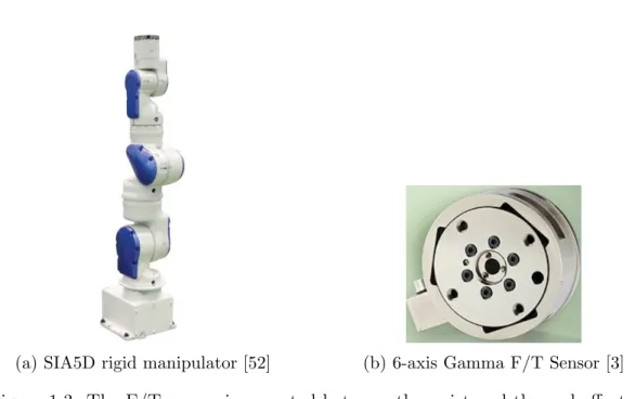
The SIA5D robot made by Yaskawa is a 7-DOF rigidly actuated industrial manipulator shown in Figure 1.3a. It’s payload is 5kg and its 7-DOF allows for extra dexterity and better maneuverability in tight spaces. [52] For this research, the robot includes a Gamma F/T sensor made by Industrial Automation between the wrist and end-effector as shown in Figure 1.3b. The main benefit of using this F/T sensor is the high signal to noise ratio and the signal is amplified, which leads to minimal noise distortion. [3]
(a) SIA5D rigid manipulator [52] (b) 6-axis Gamma F/T Sensor [3]
Figure 1.3: The F/T sensor is mounted between the wrist and the end-effector. 1.2.2 The HEBI Series Elastic Manipulators
Series elastic actuators contain an elastic element such as a spring within the actuator itself. When compared to rigid manipulators, research in elastic actuators is a relatively new field of study. [6] According to Williamson [50], although rigid robots provide good performance in position control, they are more likely to become unstable when employed in force control applications compared to series elastic actuators. This is due to the high stiffness and large forces produced from small displacements. The compliant component within the actuator acts to filter shock forces, make force control easier, and add an extra layer of safety to the robot and environment with some decrease in position control capabilities. [50]
Figure 1.4b. These actuators are made by HEBI Robotics. [16] This manipulator (shown in Figure 1.4a) can easily be taken apart and re-built to form another ma-nipulator with varying degrees of freedom. The main advantages of a mama-nipulator composed of these types of actuators are that they allow for simultaneous control of position, velocity, and torque. These are extra advantages on top of those already inherent to series elastic actuators.
In terms of haptic applications, these actuators continually publish data rep-resenting the current state of torques imparted on them and can be used to find the forces and torques imparted on the end-effector. Calculating the forces and torques on the end-effector is discussed in greater detail in a later section. The ability to continu-ally have the end-effector F/T data makes it a prime candidate for haptic performance evaluation and comparison to such performance on other types of manipulators.
(a) 6-DOF Series Elastic Actuator
(b) HEBI Series Elastic Actuator [16]
Figure 1.4: The series elastic actuator employed by NRG at the University of Texas at Austin.
1.2.3 Gough-Stewart Platforms
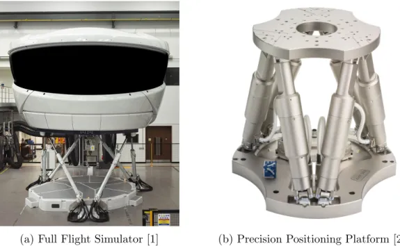
A Gough-Stewart Platform is a kinematically complex, parallel closed-chain manipulator. With this complexity, though, comes a full range of motion in six degrees of freedom. The concept of a parallel closed chain manipulator has essentially opened up an entire field of research and provides for a vast number of possible applications. [12] Some of the many applications include flight simulation, precision material handling, and medical rehabilitation. [12] [27] [9] Two such examples are shown in Figure 1.5. There are various configurations and modes of actuation for these types of manipulators. Some are actuated via prismatic actuators and others
via rotary.
(a) Full Flight Simulator [1] (b) Precision Positioning Platform [27]
Figure 1.5: Two examples of industry applications for Gough-Stewart Platforms.
1.2.3.1 A Novel Haptic Feedback Device
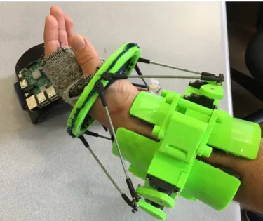
A wearable form of this manipulator (shown in Figure 1.6) was designed and fabricated by a senior design group at the University of Texas at Austin and one of the applications now includes haptic feedback (kinaesthetic and tactile). [10] The kinaesthetic haptic feedback is achieved when the haptic device moves in response to forces and torques on the end-effector. Tactile haptic feedback is achieved by employing vibration motors in the glove that are activated when a certain threshold force or torque is surpassed on the end-effector of the industrial manipulator.
for pre-recorded operations or user commanded movements. Real-time implementa-tion would require taking the existing standalone software package associated with this manipulator and modifying it such that it can communicate with other software packages, sensors, and actuators. This was achieved through the integration of the software to the ROS framework. The framework provides for the interfacing of data between another manipulator and the Gough-Stewart Platform controller. It also provides the capability of implementing the haptic feedback system alongside exist-ing ROS packages such as TeMoto and the various manipulators considered in this research. The controller used for the haptic device was a single-board Linux computer called a Raspberry Pi. In completing the integration of this haptic feedback device to ROS, the quantification of its effectiveness with regard to these types of systems could then be determined.
1.3
Research Objectives
The main objectives of this thesis are to utilize a novel haptic feedback de-vice to mitigate issues related to situational awareness (or lack thereof) and sensory overload while enhancing operator experience when controlling or supervising an in-dustrial robotic process as follows:
• Take existing standalone hardware and software associated with a Gough -Stewart Platform configured as a novel haptic feedback device and enable the capability of interfacing among other software packages, robotic systems, and sensors.
• Develop and compare metrics in haptic performance among three different vari-ations of open chained industrial manipulators.
• Integrate the haptic device to a hands-free teleoperation system calledTeMoto.
• Streamline design requirements of the haptic device for future research endeav-ors.
1.4
Thesis Organization
The completion of the objectives stated in the previous section and the process through which they will be achieved is outlined in this thesis as follows:
• Chapter 2 will review previous efforts with regard to haptic applications in robotic teleoperation in the Nuclear Industry. Next, this chapter will discuss
current advancements in this field of research with special emphasis on wearable haptic devices. Subsequently, this chapter will review literature on various F/T applications among different industrial manipulators to provide context to how those variations relate to haptic feedback applications.
• Chapter 3 will convey all necessary analytical and technical considerations with regard to inverse kinematics of the Gough-Stewart Platform, Force/Torque data acquisition, and digital signal processing techniques.
• Chapter 4will discuss implementation of hardware and software performed to meet the specified objectives. This includes detailed information on hardware design and software structure used to integrate the system to ROS.
• Chapter 5 communicates experiments performed to validate implementation. Experimentation will include performing tests with the haptic device as it inter-faces with each specified robotic system. This chapter will conclude by stating all results obtained.
• Chapter 6 summarizes conclusions drawn in performing this work. It will fi-nally conclude with suggestions for a path forward and a description of potential future work to be performed.
Chapter 2
Literature Review
Many of the concepts used in the implementation and testing of the examined haptic feedback mechanism are based largely on relevant literature. This chapter begins by reviewing some efforts in teleoperation and haptic feedback in the Nuclear Industry. It then assesses recent developments in wearable haptic devices in more gen-eral robotic applications while providing special emphasis on designs and the metrics used to quantify those designs. Their effectiveness and validity with respect to differ-ent robotic systems is also explored. We then review challenges faced in haptics and analyze efforts in mitigating those challenges. Finally, a review of Force/Torque (F/T) concepts and implementations among rigid and series-elastic industrial manipulators is investigated to provide context to how they may affect haptic performance.
2.1
Review of Efforts in the Nuclear Industry
The field of haptic feedback research for robotic manipulation has been around for many years. Some early applications were brought about in the advent of teleop-eration in nuclear environments. Robots and other mechanisms were teleoperated to perform tasks that were hazardous from safe locations. This proved the need for an interface through which the operator could control and receive information about the
robot and its interaction with its environment. Examples of teleoperation systems and haptic devices in the nuclear industry are presented in this section.
2.1.1 Teleoperation
One of the earliest teleoperation devices employed in a hazardous environment was performed at Argonne National Laboratory by Goertz [15]. The system was unilateral and consisted of a master-slave mechanism. The mechanism was used to manipulate nuclear material with a pair of tongs behind a shielded lead glass barrier (Figure 2.1). It was fully mechanical and comprised of linkages connecting the slave device to the master device. Any movement the operator made with the master mechanism was emulated in sync by the slave mechanism. When tested, it was concluded that the average person could only learn to operate the system in a short amount of time if they had good eye sight. This was because the slave mechanism was approximately one meter away. It was also found that if the operator used only one eye, the process was even more difficult due to lack of depth perception.
Based on conclusions drawn by Goertz [15], it is apparent the operator lacked information. Forces were not directly sensed and difficult to infer. If they were, sensations were distorted due to friction and reaction forces among the linkages. Also, vision was the only sensory mode used to attain information. Based on the distance, performing fine contact tasks would be difficult. Furthermore, there was no apparent benefit regarding force amplification in the system. This meant the range of objects manipulated was limited by the force imposed on the master device.
Figure 2.1: Master-Slave Mechanism for handling nuclear materials [15]
As technology progressed, electronic systems became available to control mech-anisms in teleoperation. Goertz built the first electric bilateral master-slave mecha-nism in 1954. [36] Fully mechanical teleoperation systems were no longer necessary. A notable electronic system employed for maintenance of a nuclear fusion reactor is outlined in [33]. When the fusion process occurred, the reactor itself became activated due to high energy scattered neutrons. The electronic servo-manipulator performed maintenance tasks upon temporary shutdown of the reactor. Although the system did not provide haptic feedback to the operator, it augmented the operator’s force applied to the master device. This allowed the operator to lift heavy items within the reactor by imparting a fraction of the required lifting force to the master mechanism. This proved one of the major advantages of electronic systems. As capabilities fur-ther expanded, robotic teleoperation systems with autonomous and semi-autonomous
features emerged and were proposed for new tasks within the nuclear industry. Standard nuclear power reactors must run at full power for as long as possi-ble to maximize earnings. To ensure safe maintenance and monitoring while running, emphasis is placed on implementing robotic teleoperation systems. According to Kim et al. [20], some of the possible applications set forth by the Korea Atomic Energy Research Institute (KAERI) include: maintenance work in the coolant systems of a Pressurized Water Reactor (PWR) and inspection of pressure tubes in the primary heat transport system of a Pressurized Heavy Water Reactor (PHWR). If using tele-operation, such tasks are performed without powering down the reactor. This process also lends its control to the expertise of the operator and specific areas of interest can be monitored or maintained. Providing the user with enhanced telepresence1via haptic feedback was becoming more important. Such feedback was achieved with elec-tronic sensors that obtained and transmitted data communicated via haptic interface.
2.1.2 Haptic Interfaces
While early teleoperation systems may have been successfully implemented without haptic feedback, more contemporary systems in the nuclear industry have included it as a means to relay information obtained from the robot being controlled. Some examples are outlined in [11, 19, 24], in which variations of F/T information is conveyed via haptic interface. Though F/T data obtained and transmitted from the 1Telepresence is the sensation of being in the same environment as the robotic system being
robot is most commonly used, the haptic rendering does not always need to be based on this type of data. For example, in [37], an Omega 7 made by Force Dimension is used as a master haptic device in a nuclear facility to control a 7-DOF industrial manipulator. The manipulator is used to perform tube cutting and welding at large heights. To keep the manipulator from entering a singularity, a virtual guidance is provided via force feedback. This is achieved by calculating the manipulability ellipsoid of the robot from its Jacobian Matrix and varying force applied by the haptic mechanism based on the size and direction of the ellipsoid. [37] Haptic rendering has even been employed for detection of radioactive sources using an Unmanned Aerial Vehicle (UAV). In [2], the user controls a UAV in the vicinity where there is thought to be a radioactive source. A CdZnTe spectroscopic gamma-ray detector is mounted on the system and the user feels force feedback that increases as the user gets closer to the source.
Another haptic mechanism tested in the nuclear industry was analyzed by Sabater et al. [32]. This bilateral system is shown in Figure 2.2 and utilized a Gough-Stewart Platform as a means of haptic feedback. The ground link of the master mechanism is stationary and the linear actuators are replaced with cable-driven pan-tographs. The master mechanism is shown in Figure 2.2a and was used to control and receive force reflection data from an identical parallel platform shown in Figure 2.2b. The slave platform could be used for inspection, maintenance, and dismantling tasks by climbing up pipes. The master haptic mechanism provided an easy and intuitive interface because of its 6-DOF design. It is apparent that great strides have been made in haptic feedback in the nuclear industry. This is due to the innately
hazardous tasks involved and the need for the operator to receive information about a robotic process through more sensory modes.
(a) 6-DOF Gough-Stewart master haptic mechanism
(b) 6-DOF climbing robot
Figure 2.2: Bilateral Master-Slave teleoperation system for climbing with kinemati-cally similar mechanisms [32]
2.2
Developments in Wearable Haptic Devices
This section reviewswearable haptic feedback devices whose uses encompass a broader field of robotic applications. This is done to gain a comprehensive perspective on the variety of these types of devices. Special emphasis is placed on design con-siderations and implementations. Furthermore, a review of test metrics to examine how such design considerations and implementations are validated is presented. This review is done to outline similar metrics for the haptic feedback device examined in this thesis. Those of which, will also be presented, but in a later chapter. Exten-sive efforts in the field of wearable haptic feedback devices have been made, such as in [4, 7, 34, 38], but a more detailed review of three specific devices, follows.
is shown in Figure 2.3 and is proposed for use with a rescue robot. It is implemented in a hands-free teleoperation system that utilizes the ROS framework and a Leap Motion hand-tracking sensor. It exploits Jamming Phenomenon2 to emulate grasping sensations experienced by the robot. When the robot grasps an object, the jamming pads/tubes stiffen, limiting the operator’s ability to close their hand as if they were actually grabbing something. Two of the tests performed on this system determined the dynamic response of the device to: a prompt removal of a pre-loaded force on the manipulator end-effector and an applied step input force to the manipulator end-effector, both with varying initial pad/tube pressures on the haptic device. It was found that this type system was a viable means of feedback if the user gripped their hand slow enough. This was due to the slow mechanical response (Jamming Phenomenon) of the device. Although there was latency in mechanical response, such was compensated for by incorporating vibration motors as tactile feedback that activated as soon as contact with the end-effector was made. The main limitation of this devices is its inability to convey a greater range of F/T sensations in multiple directions.
2Occurs when a liquid-like material within a membrane transitions into a solid-like material with
(a) Proposed wearable haptic device with Jamming Tubes
(b) Proposed wearable haptic device with Jamming Pads
Figure 2.3: Prototype devices tested for rescue robotic application [56]
Another design was proposed by Prattichizzo et al. [29]. This device is a wear-able 3-DOF parallel haptic feedback device that is worn on the user’s finger and is shown in Figure 2.4. Although this device only provides cutaneous3 feedback, it is implemented in such a way that force vectors can be conveyed via pulleys and cables. In this study, design guidelines were set forth to maximize wearability and hardware performance. The statics, kinematics, and controls were sequentially specified. Fur-ther, a relationship between position of the moving platform and force exerted by the device was developed. To test wearability, a small user study was performed. Regarding hardware performance, an experiment in which small force sensors were placed at the interface between the user’s finger and a location near each pulley was performed. This experiment was used to validate the magnitude of force exerted near
each DOF by inputting reference step and sinusoidal force signals to the device con-troller. It was found by Prattichizzo et al. [29] that the dynamic response (rise time, bandwidth, etc.) was stable and accurate and errors were within acceptable limits. The wearability also proved acceptable among test subjects when asked in a survey after using the design. The primary shortcoming of this device is it’s lack of ability to convey full kinesthetic haptic feedback.
Figure 2.4: Proposed design for a wearable haptic device. The authors specify the items in the diagram as: static platform (B), three motors (A), mobile platform (C), three cables (F), three pulleys (E), and force sensors (D) [29]
Another wearable haptic feedback device was proposed and tested in [39]. This soft device is shown in Figure 2.5. It is wrist mounted and pneumatically actuated to provide kinaesthetic feedback. It employs pneumatic artificial muscles to convey sensations of torque. Set forth in this work were methods in selecting design implementations as well as placement for sensors. The sensors tracked position, angles, and velocities of the user’s wrist to aid in control efforts. It was ensured that the torques imparted were safe by experimenting with a 3D printed hand, varying
tube pressures, and comparing results with [25]. An experiment in which users were tasked with following a linear and sinusoidal path on a computer screen with and without haptic feedback was conducted using the tracking data from the sensors. The haptic feedback was engaged as a virtual guidance when the users deviated from the specified path. The results obtained were mixed, but ultimately, it was concluded that this device effectively helped users trace a nonlinear path but lacked effective feedback for smaller deviations off course. The final intended use of this device is for teleoperation with a robot in which similar virtual guidance fixtures are employed. The primary shortcoming of a system of this physical complexity is its lack of analytical formulation through which experimental results can be compared. Thus, much of the comparisons required the use of sensor data that could succumb to inaccuracies or improper configuration.
2.3
Force-Torque (F/T) Applications
This section outlines and reviews literature on two primary F/T applications among industrial manipulators that are either rigid or series-elastic actuated. This is presented to highlight contrasts in F/T performance. It is also presented to give context to how such contrasts could pose varying implications to haptic performance. 2.3.1 Force Control
One of the primary considerations when comparing a manipulator that is rigidly actuated to one that is series-elastic actuated, is control. A suitable appli-cation through which to make this comparison is impedance control4. The qualities that define such a comparison are outlined in [42], where it is stated that two defining features include the hardware of a robot and a proposed controller (software). In this outline, Song, Yu, and Zhang [42] place emphasis on designing a controller, in which the dynamics of the robot are modified with a specified control law to achieve ap-parent dynamics that are better suited for a required application. Although control architectures among robots with differing actuation schemes are not explicitly ex-plored, a comparison in trade-off performance and capabilities provides some insight to parallels that may exist when considering differences in haptic performance. 2.3.1.1 Rigid Manipulators
Rigid robots are good for repetitive tasks where the environment is uncon-strained and unchanging such as in many manufacturing assembly lines. Such robots
are well suited for rendering high impedance, robust and accurate position control, and having compact mechatronics. [6] Nonetheless, modern controllers allow for the simultaneous control of position and force in instances where: the environment is changing, or the environment may succumb to damage. One example is stated in [44], in which a manipulator is used for a window washing task. If solely position control were employed, any deviation away from the specified trajectory could cause the robot to either break the window or not make contact with the window. Therefore, it is necessary to implement force control in the direction normal to the window and position control in the two directions parallel to the plane of the window. Efforts have been made to implement control algorithms that allow the controller to adapt to a lack of knowledge about the inherent dynamics of the manipulator such as in [8], or an unknown or changing environment such as in [18]. Some of the primary disad-vantages associated with rigid manipulators include: instabilities in force control and large, possibly destructive forces induced during a collision. [6]
2.3.1.2 Series-Elastic Manipulators
When considering a series-elastic actuated manipulator, some shortcomings associated with rigid manipulators are reduced with some trade-offs. Series-elastic manipulators are innately compliant due to their hardware configuration, namely, the elastic component within the actuators. Some of the benefits include the ability to render low impedance, robust force control, and safety, all at the cost of a loss in fidelity of position control. [6] Although implementation of force control can improve performance of a rigidly actuated robot, employing a series-elastic actuator could
circumvent or at least limit the need for control algorithms that would give the rigid manipulator compliant features. This is because for a rigid robot, force control sta-bility depends on the environment stiffness whereas, for a series-elastic robot, force control stability depends on the stiffness of its own actuators and is increased by the built-in compliance with the trade-off that sensitivity is decreased. [5] Series-elastic actuators are well suited for environmental interactions that may be changing or not well understood. Some examples include legged robots, and exoskeletons. [28]
2.3.2 Haptic Feedback Considerations
Another F/T application is haptic feedback. Among industrial manipulators, forces and torques imparted on the end-effector are found by either mounting a F/T sensor between the wrist of the manipulator and the end-effector, or by using joint torques and the respective dynamic model of the manipulator and environment. The latter method is described analytically in a later chapter, but high level compar-isons of both methods used, highlight differences that could pose variations in haptic performance.
2.3.2.1 Force-Torque Sensor
Wrist mounted F/T sensors are usually composed of an array of strain gauges that delineate or decouple forces and torques along three axes. [44] When using a F/T sensor purchased commercially, the task of performing digital signal processing such as adding filters, increasing sensitivity, and amplification of signals has likely been performed by the manufacturer. Though these improvements come with the system,
these types of sensors are costly. High cost is one of the shortcomings. Another shortcoming is a lack of hardware agnosticism in that, F/T sensors add unwanted inertia to the robot and can be bulky. Efforts that have been made to mitigate such shortcomings are outlined in [40] in which a neural-network approach is taken to estimate force for haptic feedback using limited joint data or in [23] where a novel force sensing device is designed for haptic feedback in a surgical environment.
2.3.2.2 Joint Torque Method
Another method of attaining F/T data for haptic feedback is using joint torques. This method circumvents the need for a F/T sensor but also has important trade-offs. Furthermore, such data is attained in different ways among manipulators with varying actuator types. Rigid manipulators with electric motors calculate the torque at each joint by quantifying the increase in current draw. This increase is induced by a load on the end-effector caused by interaction with the environment. The increase in current draw is proportional to torque at that joint. A primary con-sideration in this situation is noise generated in the signal. Recent efforts aimed at mitigating this issue using an Extended Kalman Filter have been proposed in [47] and [55]. Series elastic manipulators calculate the torque at respective joints by em-ploying a position sensor along the elastic element within the actuators and using a variation of Hooke’s Law. [28] The F/T signal generated is less noisy than that of a rigid manipulator. Nonetheless, the main drawback of using joint torque method on either type of robot is signal noise generation. If not properly processed, F/T signals could affect haptic performance.
2.4
Summary
The implementation and testing of the haptic feedback mechanism examined, builds upon previous work and concepts specified in the respective literature outlined in this chapter. Section 1 reviews efforts in nuclear applications. Namely, it discusses the progression of teleoperation in nuclear environments and the eventual need for a haptic interface. Further, it outlines examples of designs and implementations of haptic interfaces within the nuclear industry. Section 2 discusses developments in wearable haptic devices in a broader range of robotic applications and provides special emphasis on design, implementation, and the metrics through which they were validated. Finally, section 3 reviews efforts and concepts related to F/T applications among rigid and series-elastic actuated manipulators to display characteristics that could pose variations in haptic performance.
Chapter 3
Analytical Models
This chapter presents analytical models that define the functionality and en-hance performance of the haptic feedback device. First, a summary of the inverse kinematics of the device is provided. Next, the model used for end-effector F/T data acquisition using joint torques is presented. Finally, a description of the digital signal processing techniques that were tested and implemented is provided. The follow-ing sections assume an understandfollow-ing of coordinate transformations and manipulator dynamics.
3.1
Gough-Stewart Platform Inverse Kinematics
A Gough-Stewart platform is a parallel manipulator that has a base platform and a moving platform. They are connected by links with varying lengths. There are many actuation configurations for these types of manipulators. The most common is linear-prismatic with spherical joints at the platforms such as that shown in Figure 3.1. This type is called a General Stewart Platform (GSP). [45] Because the forward kinematic problem is highly non-linear and necessitates iterative methods and possible use of sensors, focus is placed on finding an inverse kinematic solution. [45] This entails simultaneously determining the length of each link, given a desired orientation and
position of the moving platform with respect to the base platform.
Figure 3.1: General Gough-Stewart Platform. [13]
The analytical model and notation used is based on [13] and [45], and a more in depth formulation can be found in these works. A summary of how the model is used in the haptic feedback device, is presented.
(a) General Link Configuration (b) Vector Diagram
Figure 3.2: GSP Configuration
Consider Figure 3.2. The orientation and position of the top platform can be described with respect to the base platform with
p Rb =Rz(γ)Ry(β)Rx(α) (3.1) and p Tb = tx ty tz T , (3.2)
respectively. In Eq. 3.1 and 3.2,pR
b is a rotation matrix that defines orientation with
Rx, Ry, Rz as rotations about the X, Y, Z axes, respectively, and pTb is the linear translation vector with coordinates tx, ty,and tz. Also
p Rb = bRp T = bRp −1 (3.3) and
are the inverse relationships. The vector links,Li, and thus, link lengths, |Li|, can be found by
Li =pTb+pRbpPi−Bi =Pi−Bi (3.5) and
|Li|=kLik2 (3.6)
where kLik2 is the euclidean norm, Pi and Bi are vectors from the base coordinate frame to theith connections on the moving platform and base platform, respectively. For a GSPi∈ {1,2,3,4,5,6}.
When considering a prismatically actuated GSP, Eq. 3.1-3.6 would provide sufficient information about link lengths, given a desired position and orientation for the top platform. Because the haptic feedback device is actuated via rotary actuators that are attached to the base platform, further steps must be taken and are detailed in [51] and [45], but a summary follows.
(a) Vector Diagram (b) Angles for Even and Odd Servos
Consider Figure 3.3. The center of the platforms is where the coordinate frames are placed. Each servo motor on the haptic feedback device is placed radially at a constant distance Rb from the base frame. They are also placed at a constant angle γi with respect to the base frame x-axis. By design of the haptic feedback device, the servos have even and odd configurations which are shown in Figure 3.3b. For a rotary actuated GSP,Li is now aneffective leg length. The point of connection between the servo horn and the push rod is labeled, mi. The servo horn and push rod have constant lengths Rm and D, respectively. The push rod connects the servo horn to the top platform. Also, Mi is a vector from the base frame to connection point mi. Based on Figures 3.2 and 3.3, it follows that
bi = xi yi zi T = Rbcos (γi) Rbsin (γi) 0 T (3.7) and pi = p xi pyi pzi T = Rpcos (pγi) Rbsin (pγi) 0 T (3.8) in which, bi and pi are coordinates to the connection points on the base and moving platform, respectively, from their own coordinate frame. Also
Rm =Rmi =|Rm|=|Mi−Bi| (3.9) and
D=Di =|D|=|Pi−Mi|. (3.10) A transformation must be performed to find the vectorMi in which
where xmi, ymi, and zmi are vectors from the coordinate frame attached to the servo to the connection point mi. It follows that Mi is a function of servo angle ∆i. This angle must be be found that satisfies
R2m = (Mi(∆i)−Bi) T (Mi(∆i)−Bi) (3.12) D2 = (P i−Mi(∆i)) T (Pi −Mi(∆i)) (3.13) |Li|2 = (Pi−Bi)T (Pi−Bi) . (3.14) After combining terms, performing substitutions, and utilizing trigonometric identi-ties, it can be found that
∆i = sin−1 p ±ci (a2 i +b2i) ! −tan−1 bi ai (3.15) in which ai = 2Rm(pzi−zi) (3.16) bi = 2Rm[sin (γi) (pxi−xi)−cos (γi) (pyi−yi)] (3.17) ci =|Li| 2 −D2+R2m (3.18)
for both even and odd servos. The calculation of this angle for each servo at a given instant, simultaneously satisfies the equality for each of the ith effective leg lengths,
|Li|, given a desired orientation and position of the top platform.
3.2
Joint Torque Model
To provide real-time kinaesthetic haptic feedback, the state of environmental forces and torques imparted on the end-effector of the industrial manipulator must
be determined. This information is scaled and passed to the haptic feedback device controller to modify the desired position and orientation of the top platform. The data is contained within a vector, F, in which
F =
Fx Fy Fz Tx Ty Tz
T
(3.19) and is also known as a Wrench. The wrench contains components of force (F) and torque (T) in theX,Y, andZ directions, respectively. It can be calculated using mea-sured joint torques and the underlying dynamic model of the robot. A full derivation can be found in [44], but a high level summary is presented.
The Jacobian matrix, J(q), of a specified industrial manipulator relates joint velocity to end-effector velocity. The vector, q ∈ Rn, represents the generalized coordinates of the n-DOF manipulator. The Jacobian matrix can also be used to relate virtual joint displacement to virtual end effector displacement to show that
τ =J(q)T F (3.20)
in which, τ ∈ Rn is a vector of manipulator joint torques. When an industrial manipulator comes in contact with the environment, its corresponding differential equation of motion is of the form
M(q) ¨q+C(q,q˙) ˙q+g(q) +J(q)T Fe=u (3.21) in which M(q) ∈Rn×n is the inertial matrix, C(q,q˙)∈
Rn×n is the Coriolis matrix,
g(q) ∈ Rn is the vector of gravitational torques, J(q)T
Also, for a series-elastic manipulator, there are extra dynamic considerations to be made. These are due to the elastic component in each actuator. Namely,
Bθ¨+u=um (3.22)
u=K(θ−q) (3.23)
where B ∈Rn×n and K ∈
Rn×n are the damping and stiffness matrices of the elastic elements, respectively,θ ∈Rnis the deflection of the elastic element in each actuator, and um is the motor torque. Nonetheless,
Fe =
J(q)T
−1
(u−(M(q) ¨q+C(q,q˙) ˙q+g(q))) (3.24) is the resulting wrench signal passed to the haptic feedback device controller.
3.3
Digital Signal Processing
When joint torques are measured on an industrial manipulator, the signal usually contains a large amount of noise. The noise occurs partly because of dis-continuities in the signal when sensors convert an analog input quantity to a digital output quantity. [54] This results in a wrench signal that also contains a large amount of noise and causes unintended vibrations in the haptic feedback device. Steps were taken to minimize noise by testing and implementing different digital signal processing techniques. Those of which, are summarized in this section.
3.3.1 Low Pass
A low-pass filter attenuates signals whose frequency is above a specified cut-off frequency and allows signals below the cut-cut-off frequency to pass. The cut-cut-off
frequency is one of the design parameters to be selected. Low-Pass filters are used for smoothing noisy signals. In depth explanations of these types of filters are found in many texts such as [14].
3.3.1.1 Moving Average Filter
The Moving Average filter was tested first. This is due to its simplicity and ease of application. An in depth analysis and description can be found in [41]. For testing it was implemented as
y[i] = 1 M M−1 X j=0 x[i+j] (3.25)
in which, x is the input signal, M is window size or number of samples, and y
is the output signal. This filter is good for white noise reduction in preliminary testing and has a good step response, but has a slow roll-off and bad attenuation characteristics. [41] The moving average filter is loosely considered a low-pass filter because although it is useful for smoothing a signal, a cut-off frequency cannot be specified. This is one of the limiting factors in this type of low-pass filter.
3.3.1.2 Butterworth Filter
The next filter tested was a low-pass Butterworth filter. An open source implementation from a Python package called SciPy was used. [35] A Butterworth filter has magnitude response of
|H(ω)|2 = 1
and a transfer function |H(s)|2 = ω N c QN K=1(s−pk) (3.27) in which, N is the filter order, ω is the sampling frequency, pk are the pole(s), and
ωc is the cutoff frequency. After choosing parameters, the filter transfer function can be found. Using the polynomials of the filter, a linear filter can be applied along one dimension. The linear filter from SciPy is based on a version of the standard difference equation and an initial state must be given. The initial state was found using the first input signal. This standard difference equation uses present and past inputs as well as past outputs to compute the current output. The Butterworth filter has the flattest frequency response for the signals not attenuated.
3.3.2 Single State Kalman Filter
The final filter tested was the Single State Kalman filter. It is a recursive algorithm that estimates the state of a process for a given signal. The signal may contain uncertainties such as noise. The filter used, was based on [48]. In summary, the goal is to find the kth state estimate, ˆx
k, of the process. The steps to implement this filter are shown in Figure 3.4, and encompass an initial estimate, prediction step, measurement, and update step. For the initial estimate, the ˆxk−1 state estimate and state probability, Pk−1, must be provided. The state estimate and state probability immediately following the prediction step is based on the prior estimate as
ˆ
x−k =Axˆk−1+Buk−1 (3.28)
in whichArelates the state estimate to the previous state estimate,Brelates the state estimate to an optional control input, uk, and Q is the process covariance provided in the initial estimate. A measurement, zk, is taken. The update step uses the prior step and measurement to compute a Kalman gain, Kk, update the state estimate, and update the state probability. This is done with
Kk =Pk−H T HP− k H T +R−1 (3.30) ˆ xk = ˆx−k +Kk zk−Hxˆ−k (3.31) Pk= (I−KkH)Pk− (3.32)
where H relates the state estimate to the measurement, R is the measurement co-variance provided in the initial estimate, and I is the identity matrix (1 is used for single state). The output state estimate and state probability from the update step is fed back into the prediction step and the process is repeated. After some iterations, the output state estimate converges with values near the actual state with minimal noise.
3.4
Summary
This chapter presented analytical models that define the functionality and enhance performance of the haptic feedback device. A summary of the inverse kine-matic model was presented. The model for F/T data acquisition from industrial manipulator joint torques was outlined. Finally, the digital signal processing tech-niques tested and implemented, were summarized. These techtech-niques assumed the components within the wrench signal were decoupled and linear. Although valid for contact tasks within a small region away from singularities, this assumption can pose implications to performance otherwise. This is because because wrench components are coupled and non-linear when attained via the Joint Torque Model. The mitigation of such implications are discussed in a later chapter.
Chapter 4
Implementation
This chapter outlines how the standalone haptic feedback device was provided capabilities for real-time interfacing with external hardware and software. The chap-ter begins with a high level summary of the implementation set forth by the senior design group in [10]. Next, the software configuration is presented, starting with an introduction to the Robot Operating System (ROS) framework, followed by a descrip-tion of modificadescrip-tions performed to utilize the framework, and an overall structural outline. Finally, the hardware arrangement that allows for a manipulator agnostic haptic interface is presented.
4.1
Initial Setup
The senior design project outlined in [10], specified requirements for a haptic interface implemented in robotic systems that performed contact tasks. The focus was on prototyping a safe device that communicated intuitive kinaesthetic and tactile feedback. The device was to be implemented with an existing hands-free teleoperation system used in the Nuclear and Applied Robotics group at the University of Texas at Austin. The device is fully modular, portable, and can be worn by the user as shown in Figure 4.1. The servo motors provide the kinaesthetic haptic feedback via
translation and rotation of the top platform. A spring-like interface connects the platform to the glove worn by the user. Vibration motors within the glove provide tactile feedback when a threshold force is reached. The controller for this system is a Raspberry Pi 3, which is a single board computer with a Linux based operating system called Ubuntu Mate.
Figure 4.1: Haptic Feedback Device
Regarding software, the system was composed of Python modules giving the device its functionality. A Graphical User Interface (GUI) was setup for ease of calibration and testing upon launching the system. The GUI is shown in Figure 4.2. Using the GUI, the user could modify the desired position and orientation of the top platform. This was accomplished with Python modules that calculated servo angles based on the desired pose of the top platform and sending the Pulse Width Modulated
(PWM) signals to the motors. The main features the GUI provided were: using sliders to modify pose of the haptic device in “Live Mode”, planning and executing a desired pose in “Plan Mode”, and the option to receive input wrench data from pre-recorded contact operations by clicking the “Run” button. Upon clicking “Run”, a Python module would parse pre-recorded data from a .csv (comma separated values) file and use it to modify the pose of the top platform to simulate the haptic feedback.
Figure 4.2: Graphical User Interface
Although the senior design team was successful regarding the goals they set forth, due to time constraints, they chose to leave real-time implementation for future research. This implementation would include integration to ROS for use with different manipulators as well as the hands-free teleoperation system.
4.2
Software Configuration
For the haptic feedback device to work in real-time, a framework for data interfacing among its controller and external hardware was necessary. The framework chosen to complete this task was ROS. After integration to the framework, ROS packages could be used within a ROS work-space to expedite data interfacing and promote software re-usability. A brief summary of ROS is outlined. Also, the steps taken to achieve integration to the framework, as well as the final software structure are presented.
4.2.1 Robot Operating System
ROS is an open source framework consisting of libraries and tools used to expedite software development for robotic applications. [26] It allows for hardware abstraction and the passing of messages between different nodes, with each node providing their own independent functionalities. ROS promotes software re-usability in that general ROS packages can be created for a certain robotic system by one entity and used for a similar system by another entity with minimal modifications. An example is presented in [30], in which researchers want to develop a mobile robotic system that has a manipulator attached to it. It’s necessary for the system to have modules for obstacle avoidance and mapping, drivers to communicate with wheels and encoders, trajectory planners for the manipulator, etc.. Many of these tasks would also depend on each other. Rather than developing software for each of these functionalities from the ground up, this has likely already been implemented in ROS and can be used and interfaced by the researchers as a starting point for further
research.
4.2.1.1 ROS Graph
A node computes data. Nodes can be written in any programming language ROS supports, such as Python or C++. Nodes need no knowledge about the inner workings of separate nodes. A built-in master node calledroscore provides interfacing instruction to all nodes. If certain nodes are to communicate, the data between them usually streams through topics. A node can either subscribe to a topic or publish to a topic and each topic can only stream one message type. Another means of communication is accomplished by using a Service. A service encompasses a single pair of messages. When a client node sends a request to a server node, the server node sends back a response. This interfacing scheme makes up the ROS Graph and is shown in Figure 4.3. It can be as simple as two nodes passing data or can be scaled up to include hundreds of nodes for complex robotic systems.
4.2.1.2 ROS Packages
A ROS Package contains nodes, executables, configuration files, and other information relating to a certain robotic system. In the open source robotics commu-nity, packages are written with re-use in mind. Many packages can reside in a single ROS workspace. A ROS workspace is a repository in which packages can be created or installed. Furthermore, a package can contain other packages and encapsulate in-formation. This provides good namespacing features because it can mitigate name clashing.
Figure 4.3: ROS Graph
4.2.2 Haptic Feedback Device - ROS Integration
To integrate the haptic feedback device to ROS, a full ROS kinetic installa-tion was performed on the Raspberry Pi 3 and a workspace was generated. A ROS Package called stewart haptic was created in the workspace. The existing software for the haptic device was placed in the ROS Package. The module that initially received the pre-recorded wrench data inputs was modified into a ROS node called /haptic device. The flow of data throughout the software package was mapped. This was to ensure the module that launches the system could also initialize the node. The node subscribes to a topic streaming a wrench message. This message is published in real-time by a node within the packages controlling the industrial manipulators. The /haptic device node filters the noisy wrench signal and passes it to other modules to calculate the necessary angles for each pose of the haptic device and communicates the data to the servos. It can also simultaneously publish angles of the servos for testing purposes. The stewart haptic package could be launched peripherally with
the packages controlling the industrial manipulators. An example of the overall ROS Graph for this setup is shown in Figure 4.4 in which, the interaction is zoomed in for clarity. The /haptic device node is in green and is subscribing to a wrench topic in red.
Figure 4.4: ROS Graph for the Haptic Device and an Industrial Manipulator
4.2.3 Structure
Within the stewart haptic ROS package, the software functions as shown in Figure 4.5. With a roscore running, the module start.py can be launched. This module initializes the ROS package. The servo motors move to home position and the GUI is initialized and opened. If the “Run” button is clicked, the subscriber node called Bagclass.py is initialized and ready to receive a wrench signal. If a package
running one of the industrial manipulators is launched as well, the interfacing will begin. If the run button is not clicked, the sliders on the GUI can be moved by the user to manually modify the position of the top platform on the haptic feedback device. If no action is performed, the device waits in home position.
4.3
Hardware Interface
Once software modifications were complete, focus was placed on hardware for real-time interfacing. A physical means of data transfer between respective controllers was required. Furthermore, it was necessary that ROS correctly and simultaneously be launched on all hardware components. Below is a summary of how this was completed.
4.3.1 SSH Protocol
Since the haptic feedback device is controlled by a Raspberry Pi 3 consisting of an Ethernet port, SSH protocol was chosen to connect to other hardware. SSH protocol allows for remote login from one computer to another and the interfacing of data. The Raspberry Pi 3 requires communication with the computers launching the ROS packages for the industrial manipulators. Once it was ensured the com-puters could successfully ping each other, changes to environment variables on both computers were made.
4.3.2 ROS IP and ROS MASTER URI
When using ROS simultaneously among multiple computers, environment vari-ables must be set such that one computer runs the master node, roscore. Nodes must know where to locate the master node. This is accomplished by setting the ROS MASTER URI in the .bashrc script on both computers. The value is set to the IP address of the computer running the master node. The .bashrc is sourced when a terminal is opened and can be used for aliasing and to define environment variables.
Furthermore, each node must declare a ROS network address. This is done by setting the environment variable ROS IP, on each computer to its own IP address.
4.4
Summary
This chapter defined the initial configuration of the haptic feedback device set forth by the senior design team. An explanation of ROS was provided to highlight the means of interfacing between the haptic feedback device and the industrial manipu-lators. The steps taken to integrate the haptic device to the ROS framework as well as the final software structure were presented. Finally, the hardware configuration to achieve the integration was outlined. The ROS package that governs the haptic feedback device is hardware agnostic in that, it does not matter which manipulator is being tested, as long as the appropriate wrench message is being published.
Chapter 5
Demonstration and Experimentation
This chapter documents the demonstration and evaluation of the haptic feed-back device using different industrial manipulators, quantifies the haptic performance, and draws comparisons. This was accomplished by using the analytical formulations and implementation described in Chapters 3 and 4, respectively. Experimentation served to quantify haptic performance. The experiments and results are outlined. Finally, a discussion on results and comparisons drawn is presented.
5.1
Demonstration
The setup and configuration was different for each industrial manipulator. A summary of each demonstration is presented. Also, a qualitative description of performance is presented to outline parameters of interest before experimentation. 5.1.1 UR3 and TeMoto
As previously stated, the UR3 is a rigid 6-DOF industrial manipulator that utilizes multiple ROS packages simultaneously. Some of which include: drivers for the robot, trajectory planning packages, and the user interface. A Linux computer connects to the UR3 controller and launches all ROS packages. After the UR3 driver

![Figure 1.2: UR3 Rigid manipulator. [31]](https://thumb-us.123doks.com/thumbv2/123dok_us/10955664.2984000/19.918.370.551.279.518/figure-ur-rigid-manipulator.webp)

![Figure 2.1: Master-Slave Mechanism for handling nuclear materials [15]](https://thumb-us.123doks.com/thumbv2/123dok_us/10955664.2984000/29.918.265.654.157.486/figure-master-slave-mechanism-for-handling-nuclear-materials.webp)
![Figure 2.2: Bilateral Master-Slave teleoperation system for climbing with kinemati- kinemati-cally similar mechanisms [32]](https://thumb-us.123doks.com/thumbv2/123dok_us/10955664.2984000/32.918.167.422.240.413/figure-bilateral-master-teleoperation-climbing-kinemati-kinemati-mechanisms.webp)
![Figure 2.3: Prototype devices tested for rescue robotic application [56]](https://thumb-us.123doks.com/thumbv2/123dok_us/10955664.2984000/34.918.170.430.164.420/figure-prototype-devices-tested-rescue-robotic-application.webp)
![Figure 2.4: Proposed design for a wearable haptic device. The authors specify the items in the diagram as: static platform (B), three motors (A), mobile platform (C), three cables (F), three pulleys (E), and force sensors (D) [29]](https://thumb-us.123doks.com/thumbv2/123dok_us/10955664.2984000/35.918.327.591.376.616/figure-proposed-wearable-authors-specify-diagram-platform-platform.webp)
