Paper for International Conference of INMARTECH2008, France
Multidisciplinary Design Optimization Method
Applied to a HOV Design
Cao Anxi
1, Cui Weicheng
2 1State Key Laboratory of Ocean Engineering, Shanghai Jiao Tong University, Shanghai, 200030, China 2
China Ship Scientific Research Center, P.O.Box 116, Wuxi, Jiangsu, 214082, China
Abstract
In this paper, a Multidisciplinary Design Optimization (MDO) procedure is applied to a HOV design. Multidisciplinary decomposition and analyses have been developed for this complex system that includes hydrodynamics, structure, propulsion, weight & volume. The Multi-Objective Collaborative Optimization (MOCO) method is selected to conduct the preliminary conceptual design of the HOV. This approach was able to identify Pareto front designs. The results also demonstrate that MDO approaches are more suitable for design of the HOV and more flexible and advanced compared with the traditional design approach.
Keywords: MDO, HOV, Conceptual Design, Multi-Objective Collaborative Optimization (MOCO)
1.
Introduction
The conceptual design stage of a complex engineering design process is the most critical to its success or failure, as at this stage 75% of the final cost and performance metrics are determined. The design of a Human Occupied Vehicle (HOV) is a complex and multidisciplinary task, and the task is often divided into a set of smaller and easier tractable design problems. A complete design requires analyses of hydrodynamics, structure, propulsion, weight, control, operations, cost and the others. It is important for each of these aspects to be addressed at the conceptual design phase. The traditional approach for the design of a HOV is of a sequential order. As shown in Fig. 1, in this approach, design begins with the first discipline team, where the values of certain design variables are fixed and passed to the second disciplinary team, and so on until a complete design emerges from the last discipline. The traditional approach may lead to non-optimal system designs for many reasons including: [1]
(1) Analysis in upstream discipline may depend on results determined in downstream disciplines. In the sequential order approach, upstream disciplines must assume values which may not match the actual values when they are finally determined in the downstream disciplines.
(2) The system objectives (cost, performance, etc.) may depend heavily on results determined in downstream disciplines where design freedom no longer exists to make significant changes.
impossible for them to satisfy their constraints.
It is obvious that the traditional approach to a HOV design is not suitable for the development of modern HOVs which will become more and more complex.
Fig.1 The traditional conceptual design architecture of a HOV
The field of multidisciplinary design optimization (MDO) has emerged to develop approaches for optimizing the design of large coupled systems [2]. MDO is concerned with how to efficiently analyze and optimally design a system governed by the multiple coupled disciplines or made up of coupled components. It is a part of the concurrent engineering technology that may well be an enabling technology for complex advanced systems [3]. With the rapid growth of MDO over the past decade, MDO has been widely discussed and used not only in aerospace and aeronautical industries[4-6], but also in other complex engineering systems such as automobile[7], underwater vehicles[8, 9], ship[10] etc. and resulted in a more reliable and better design.
For the purpose of attaining the overall performance optimization of a HOV and improving procedure of a HOV conceptual design, MDO technique has been employed. The purpose of this paper is to explore how Collaborative Optimization (CO), one of the MDO methods, can be applied in the conceptual design of a HOV.
2.
Multi-Objective Collaborative Optimization (MOCO)
Collaborative Optimization (CO), one of the multidisciplinary design optimization methods, has been developed to promote autonomy while providing a coordinating mechanism that guaranteeing progress toward an optimum and maintaining interdisciplinary compatibility [11, 12]. It basically consists of a two-level optimization structure. The original structure of CO is shown in Fig. 2. Within CO, the design task is accomplished by several disciplinary teams as well as by a system-level team. The disciplinary teams are free to define their own local designs. The task of the disciplinary-level teams is to find a local design that satisfies local constraints and comes as close to that specified by system-level optimizer as possible. The system-level team is in charge of
Hydro- dynamics Propulsion Energy Structure Weight & Volume
adjusting the system variables with the goal of minimizing or maximizing the system-level objective. This problem is subjected to the interdisciplinary compatibility constraints equal to zero.
Fig2. The Basic Collaborative Optimization architecture
CO has been widely discussed and applied in practical engineering problems. Some researchers have applied it to both simple test problems[11-15] and more complex engineering design problems. These applications involve launch vehicle design[4], aircraft design[5,6,16,17], undersea vehicles design[8,9], conceptual ship design[10],and turbine engine design[18]. CO has been judged highly advantageous in its applications to practical engineering design problems. At the same time, many researchers have focused on extension or modifications to CO aimed at improving overall efficiency, permitting their use on problems with high dimensionality coupling and simplifying their implementation. In order to relieve the numerical difficulties caused by certain mathematical manipulations, the use of an approximation model has been proposed in place of the disciplinary design in CO [17,19]. To resolve the convergence problem of CO, Kroo and Manning [12] adopted the direct search method such as Hooke and Jeeves method or the probabilistic search method such as genetic algorithm instead of the gradient-based method. A variety of extensions have been made to CO including resolving the system including mixed continual and discrete design variables [1], and introduction of multi-objective formulation[20, 21].
In this study, a MOCO has been selected to handle multiobjective systems. In the MOCO, the goal of the system level optimizer is to minimize a system level multiobjective function of target variables while satisfying compatibility constraints using a Pareto Genetic Algorithm based on (PGA). PGA solves system level optimization problem with respect to system design variables. For each generation at the system level, the disciplines are optimized for each candidate design from the population. The system level optimization problem is described as equations (1-3)
System-Level optimizer
Goal: Design objective s.t.: Interdisciplinary compatibility constraints Subspace optimizer 1 Goal: Interdisciplinary compatibility S.t.: Analysis 1 constraints Subspace optimizer 2 Goal: Interdisciplinary compatibility S.t.: Analysis 2 constraints Subspace optimizer N Goal: Interdisciplinary compatibility S.t.: Analysis N constraints
Analysis 1 Analysis 2 Analysis N
1 2
:{ , ,
,
N}
Min
f f
L
f
(1). . :
i0,
1, 2,
,
S t
J
≤
i
=
L
N
(2)
.
.V
D
:x
o=
[
x
osh,
x
auxo,
x
1,
x
2,
Λ
,
x
m,
]
(3)Equations (4-7) describe the subsystem level optimization problem for a typical subsystem, in this case subsystem 1:
∑
∑
= =−
+
−
+
−
+
−
=
N i o j aux j N i o i aux i aux o o sh sh ssJ
Min
2 2 1 1 2 2 1 1 2 1 1 2 1 1 1 1)
)
(
1
(
)
)
(
)
(
1
(
)
1
(
)
)
(
)
(
1
(
)
(
:
x
y
x
x
x
x
x
x
x
(4)S
.
t
.
:
g
1≤
0
(5)(
x
ss1)
min≤
x
ss1≤
(
x
ss1)
max (6)D
.V
.
:x
ss1=
[(
x
sh)
1,
(
x
aux)
i1,
x
1]
(7)The MOCO architecture for HOV design that has been developed for conceptual design is briefly discussed, a more detailed description can be found in Ref. [21].
3.
HOV design Application
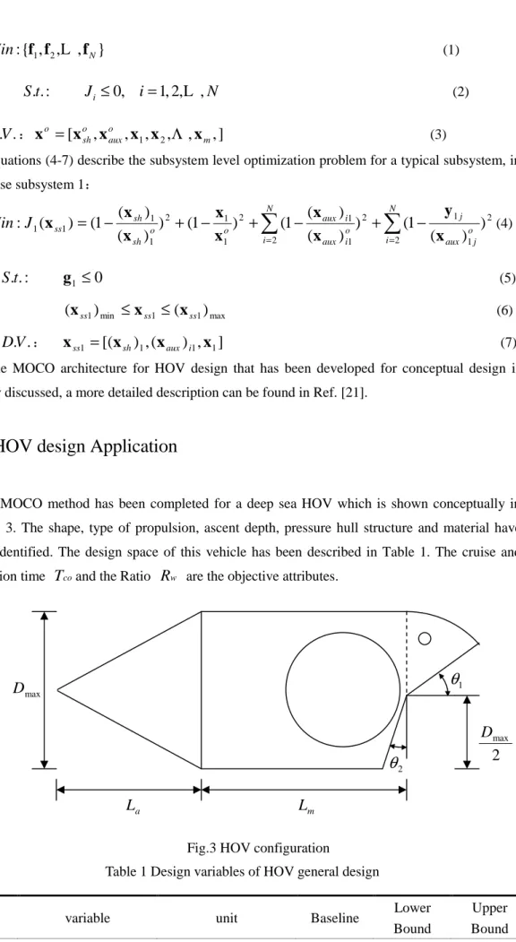
A MOCO method has been completed for a deep sea HOV which is shown conceptually in Figure 3. The shape, type of propulsion, ascent depth, pressure hull structure and material have been identified. The design space of this vehicle has been described in Table 1. The cruise and operation time
T
coand the RatioR
w are the objective attributes.Fig.3 HOV configuration
Table 1 Design variables of HOV general design
variable unit Baseline Lower
Bound Upper Bound 1
θ
2θ
2
maxD
aL
L
m maxD
1 m
L
m
4.45 4 5 2 aL
m
3.0 2.8 3.2 3D
m
3.0 2.6 3.2 4u
kn
2.5 2.5 3.0 5W
plkg
220 200 300 6E
kWh
110 90 140 7W
buokg
6374 5500 7000Firstly, we decompose the design problem into a system module and four disciplinary optimization modules: geometry & hydro, structure, propulsion, weight & volume. Figure 4 describes the MOCO architecture of the HOV design.
Fig.4 MOCO architecture of the HOV design
Equations (8-10) describe the formulation of system-level optimization problem, and Equations (11-21) describe the four subsystem optimization problems.
(1) System-level stand formulation:
:
Min
{
R
w,
T
co}
(8):
.
.t
S
J
i≤
ε
,
(
i
=
1
,
2
,
3
,
4
)
; (9):
.
.V
D
x
o=
[
D
o,
u
0,
E
o,
L
o,
R
To,
V
fo,
W
so,
V
so,
W
proo,
V
proo,
W
plo]
; (10) System optimizer Discipline 2 Structure Discipline 3 Propulsion Discipline 4 Weight & volumeo f o T o o
V
R
L
D
,
,
,
Discipline 1 Geometry & hydroo T o s o s o T o o
W
V
W
R
L
D
,
,
,
,
o pro o pro o oV
W
E
u
,
,
o f o T o s o s o pro o pro o buo o plV
W
V
W
V
W
W
W
,
,
,
,
,
,
1J
2J
3J
4J
(2) Discipline 1, Geometry and hydro subspace stand formulation:
:
Min
1(
1
)
2(
1
)
2(
1
)
2(
1
o)
2 f f o T T o oV
V
R
R
L
L
D
D
J
=
−
+
−
+
−
+
−
; (11):
.
.t
S
L
m
m5
4
≤
≤
;2
.
8
≤
L
a≤
3
.
2
m
;2
.
6
≤
D
≤
3
.
2
m
; (12):
.
.V
D
x
ss1=
[
L
a,
L
m,
D
]
; (13)(3) Discipline 2, structure subspace stand formulation:
:
Min
2(
1
)
2(
1
)
2(
1
)
2(
1
)
2(
1
o)
2 T T o s s o s s o oW
W
V
V
W
W
L
L
D
D
J
=
−
+
−
+
−
+
−
+
−
(14):
.
.t
S
2
.
6
≤
D
≤
3
.
2
m
; (15):
.
.V
D
x
ss1=
[
D
,
L
,
W
T]
; (16)(4) Discipline 3, propulsion subspace stand formulation:
:
Min
3(
1
)
2(
1
)
2(
1
)
2(
1
)
2(
1
o)
2 T T o pro pro o pro pro o oR
R
V
V
W
W
E
E
u
u
J
=
−
+
−
+
−
+
−
+
−
(17):
.
.t
S
2
.
5
≤
u
≤
3
.
0
kn
;90
≤ ≤
E
140
kWh
(18):
.
.V
D
x
ss1=
[
u
,
E
,
R
T]
; (19)(5) Discipline 4, weight & volume subspace stand formulation:
:
Min
4(
1
)
2(
1
)
2(
1
)
2(
1
)
2(
1
o)
2 s s o s s o f f o buo buo o pl plV
V
W
W
V
V
W
W
W
W
J
=
−
+
−
+
−
+
−
+
−
2 2 2)
1
(
)
1
(
)
1
(
o pro pro o pro pro o T TV
V
W
W
W
W
−
+
−
+
−
+
(20):
.
.t
S
200
300
plW
kg
≤
≤
;5500
≤
W
bou≤
7000
kg
;40
≤
ρ
swV
−
W
T≤
80
kN
;W
T≤
22
t
(21):
.
.V
D
x
ss1=
[
W
pl,
W
buo,
V
f,
W
s,
V
s,
W
pro,
V
pro]
; (22)5.1.
Results and Discussion
A Multi-Objective Collaborative Optimization has been run for 328 generation with a population of 50 HOVs. In system-level optimization problem, the relaxation factor of compatible constraints is set to 0.0001, the crossover probability, the mutation probability and the maximum generation are set to 0.9 , 0.1 and 350. For the sub-space optimization problems, the sequence quadratic programming (SQP) is used to attain the discipline optimization solution. The different
sub-space optimizations are solved in-parallel.
Results are presented in Figure 5. None of these HOV can be identified as "the best". Selection of the preferred design is up to the designer. Figure 5 provides the designer with important information to make this selection. Table 2 list four designs which is selected from the Pareto optimal solutions 0.0120 0.0125 0.0130 0.0135 0.0140 0.0145 0.0150 4.0 4.5 5.0 5.5 6.0 6.5 7.0 Parato front Tco ( h ) R w HOV1 HOV2 HOV3 HOV4
Fig. 5 Pareto optimal solutions of HOV’s multi-objective multidisciplinary design
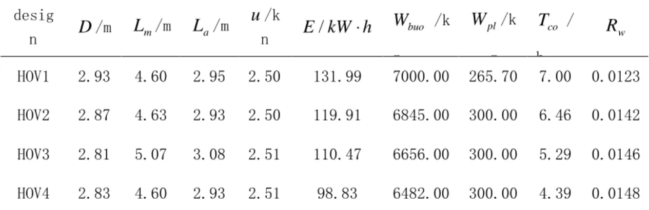
Tab. 1 The four designs in Pareto front.
desig n
D
/mL
m/mL
a/mu
/k nE kW h
/
⋅
buoW
/k g plW
/k g coT
/ h wR
HOV1 2.93 4.60 2.95 2.50 131.99 7000.00 265.70 7.00 0.0123 HOV2 2.87 4.63 2.93 2.50 119.91 6845.00 300.00 6.46 0.0142 HOV3 2.81 5.07 3.08 2.51 110.47 6656.00 300.00 5.29 0.0146 HOV4 2.83 4.60 2.93 2.51 98.83 6482.00 300.00 4.39 0.0148HOV1 and HOV4 are located at the ends of the Pareto front, and HOV2 and HOV3 are located at the middle of the Pareto front. HOV1 has the longest cruise and operation time which is up to 7 hours, but the alternative has the minimum ratio which is just 0.0123. In contrast, HOV4 has the maximum ratio and the shortest cruise and operation time. If the time is the most important performance for a HOV, the HOV between HOV1 and HOV2 are excellent choices.
4.
Summary and Conclusions
An application of Multidisciplinary Design Optimization to a HOV conceptual design has been presented. In this application, the MOCO architecture was used. The method integrates the multi-objective optimization methods within the collaborative optimization framework, which remains the main metrics of CO architecture and ability of PGA to seeking non-inferior solution set. So the method is effective in that it makes a chance to execute in-parallel for disciplinary design, and it is more flexible in that it enables the designer to select the fittest solution among the Pareto optimal set in according with their preference and the nature of the design problem. These practical advantages make the architecture well-suited for the design of HOVs.
References:
[1] Balling R J, Gale D L. Collaborative Optimization of Systems Involving Discrete Design at the Discipline Level [J]. Journal of Mechanical Design, 1998(120):32-39.
[2] Sobieszczanski-Sobieski J, Haftka R T. Multidisciplinary Aerospace Design Optimization: Survey of Recent Developments [J]. Structural Optimization, 1997, 14(1):1-23.
[3] Balling R J, Sobieszczanski–Sobieski J. Optimization of coupled systems: A critical overview of approaches [J]. AIAA Journal, 1996, 34(1):6–17.
[4] Braun R D, Moore A A, Kroo I M. Collaborative architecture for launch vehicle design [J]. Journal of Spacecraft and Rockets, 1997, 34(4):478-486.
[5] Sobieski I P, Kroo I M. Collaborative Optimization Applied to an Aircraft Design Problem[C]. AIAA Paper 96-0715, the 34th AIAA Aerospace Sciences Meeting and Exhibit. Reno, Nevada, January 15–18, 1996.
[6] Batill S M, Stelmark M A, Yu X Q. Multidisciplinary design optimization of an electric-powered unmanned air vehicle [J]. Aircraft Design, 1999(2):1-18.
[7] Kodiyalam S. Evaluation of methods for multidisciplinary design optimization, Phase I [R]. Tech. Report, NASA/CR-2000-210313, National Aeronautics and Space Administration, 1998.
[8] Belegundu A D, Halber E, Yukish M A, Simpson T W. Attribute-based multidisciplinary optimization of undersea vehicles [C]. AIAA Paper 2000-4865, the 8th AIAA/USAF/NASA/ISSMO Symposium on Multi- disciplinary Analysis and Optimization. Long Beach, CA, Sept. 6-8, 2000. [9] McAllister C D, Simpson T W, Kurtz P H, Yukish M. Multidisciplinary design optimization test
based on autonomous underwater vehicle design[C]. The 9th AIAA/ISSOM symposium on Multidisciplinary Analysis and Optimization. Atlanta, Georgia, Sept. 4-6, 2002.
[10] Kodiyalam S, Sobieszczanski-Sobieski J. Bi-level integrated system synthesis with response surfaces [J]. AIAA Journal, 2000, 38(8): 1485-1497.
[11] Braun, R. D. Collaborative Optimization: An architecture for large-scale distributed design [D]. Ph.D. thesis, Stanford University, Department of Aeronautics and Astronautics, 1996.
[12] Kroo I, and Manning V, Collaborative Optimization Status and Directions [C]. AIAA Paper 2000-4721, the 8th AIAA/USAF/NASA/ISSMO Symposium on Multidisciplinary Analysis and Optimization. Long Beach, CA, Sept. 6-8, 2000.
[13] DeMiguel A, Murray W. An Analysis of Collaborative Optimization Methods[C]. AIAA Paper 2000-4720, the 8th AIAA/USAF/NASA/ISSMO Symposium on Multidisciplinary Analysis and Optimization. Long Beach, CA, Sept. 6-8, 2000.
[14] Braun R D, Gage P, Kroo I M. Implementation and performance issues in collaborative optimization[C]. AIAA-96-4017, the 6th AIAA/USAF/NASA/ISSMO Symposium on Multidisciplinary Analysis and Optimization. Washington, September, 1996.
[15] Alexandrov N M, Lewis R M. Analytical and Computational Aspects of Collaborative Optimization for Multidisciplinary Design [J]. AIAA Journal, 2002, 40(2):301-309.
[16] Manning V. High Speed Civil Transport Design via Collaborative Optimization [D]. Ph.D. thesis, Stanford University. 1999.
[17] Jun S, Jeon Y, Rho J, D Lee. Application of Collaborative Optimization Using Response Surface Methodology to an Aircraft Wing Design [C]. AIAA-2004-4442, the 10th AIAA/ISSMO Multidisciplinary Analysis and Optimization Conference. Albany, New York, Aug. 30-1, 2004. [18] Rohl P J, He B, Finnigan P M. A collaborative optimization environment for turbine engine
development[R]. AIAA Paper, No. 98-4734, 1998.
[19] Sobieski I P, Kroo I M. Collaborative Optimization using Response Surface Estimation [J]. AIAA Journal, 2000, 38 (10): 1931-1939.
[20] Tappeta R V, Renaud J E. Multiobjective collaborative optimization [J]. Journal of Mechanical Design, 1997, 119(3): 403-411.
[21] Cao An-xi, Cui Wei-cheng. Multi-Objective collaborative optimization in multidisciplinary design for submersible [J]. Journal of Ship Mechanics, Vol.12, No.2, 2008.4.