BROSA Angle Sensor Operating Instructions
Angle sensor
Type 0804
Angle sensor Ex d
Type 0813
1 Description of the BROSA Angle Sensor
1.1 Structure and functionality
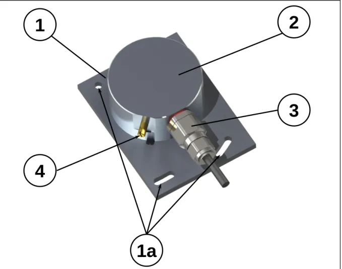
The BROSA angle sensors of types 0804 and 0813 are used to measure an angle relative to the direction of gravity in or on machines of all types. This relationship is given by the defini-tion of the measuring range in the form of defining the zero point and can be selected indi-vidually. Figure 1 shows the typical layout:
Figure 1: Angle sensor
The angle sensor consists of a base plate (1) that has facilities (1a) for mounting at the in-stallation site. It supports a housing (2) that contains the measurement electronics and has
1
2
3
1a
4
the elements necessary for the electrical connection (connector and cable, 3). The Ex d Type 0813 angle sensor is always equipped with a threaded pin (4) for electrical potential equali-sation (this is optional in the other types). Base plate and housing are made from an alumini-um alloy as standard; stainless steel is available as an option.
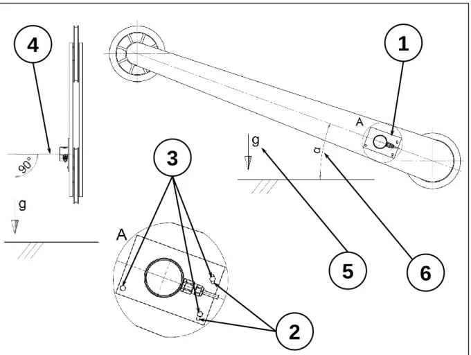
Figure 2 shows the typical installation conditions:
Figure 2: Installation conditions in an example for a crane boom
The angle sensor (1) is usually fixed at the installation site to the appropriately designed seatings (2) using securing elements (3). The normal to the measuring plane (4) is perpen-dicular to the direction of gravity (5). The measurement electronics measure the angular po-sition (6) of the angle sensor in the measuring plane and output this as an electrical signal. Versions with two measuring systems, either with output signals on separate connect-ors/cables or combined in one connector/cable, are available as options. More information can be found in the technical data sheets, which can be obtained free of charge from BROSA.
1.2 Information on explosion protection
The Ex d type 0813 angle sensor is encapsulated as pressure-resistant and thus suitable for use in potentially explosive atmospheres. The following specifications apply:
- Ignition protection types:
o II 2G Ex d IIC T4 Gb / Ex d IIC T4 Gb o II 2G Ex d IIB T4 Gb / Ex d IIB T4 Gb - Certificate numbers:
4
1
2
3
5
6
o ATEX: BVS 09 ATEX E 037 X
o IECEx: IECEx BVS 14.0110 X - Safety-related limit values:
o Active operational mode:
▪ Input voltage UE = 9…36 V DC ▪ Input current IE = 5…100 mA Use of the Ex d angle sensor in zone 0 is not allowed.
The angle sensor may not be opened inside a region with a potentially explosive atmosphere.
1.3 Label (nameplate, indication of measuring direction)
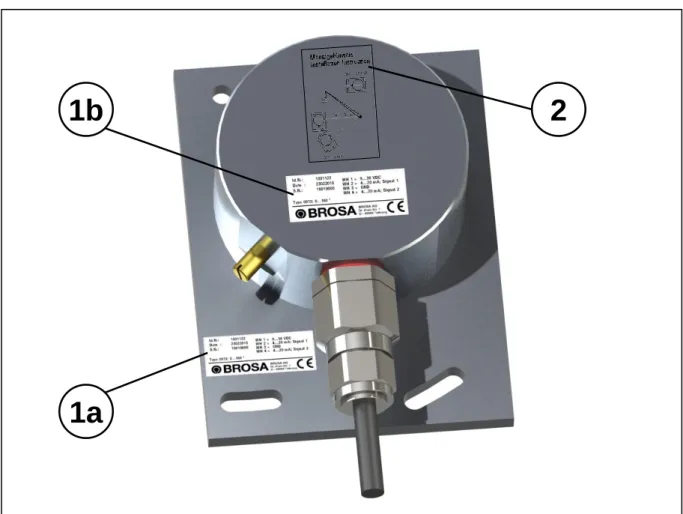
Each BROSA angle sensor is provided with a nameplate containing the information applica-ble for each variety. It can be attached either to the base plate (Figure 3, 1a) or to the hous-ing (Figure 3, 1b).
Figure 3: Nameplate positions, measuring direction
The alignment is shown on the upper side of the housing by an installation sketch (Figure 3, 2).
1a
2
1b
2 Advice on safe handling of BROSA angle sensors
WARNING! Non-compliance with the following instructions can lead to sensor damage and/or impairment of measurement results. The analysis of an erroneous measurement can result in personal injury or material damage.
WARNING! Despite their sturdy design, BROSA angle sensors may not be used for any other than the intended purpose (see Section 1.1). With improper use, dangers to life and limb of the user or third parties and/or impairment of the device in which the angle sensor is implemented or other material assets can be caused.
2.1 Handling
WARNING! BROSA sensors contain high-quality measurement electronics. Make sure you handle them carefully.
- BROSA angle sensors are delivered in secure, transport-proof packaging. We recom-mended that you remove the sensors from the package immediately prior to installation.
- BROSA angle sensors are to be protected against falling. Do not throw sensors!
- The use as a tool (e.g. for striking, slotting or levering) is not permitted; it can cause damage to the sensor and thus falsify the measurement results.
2.2 Installation and commissioning
2.2.1 General
We recommended taking the following actions in the given order using the “four-eye princi-ple”.
a) Checking the sensor – measuring point assignment: It must be ensured that the sensor to be installed is designed for use at the intended measuring point. For this purpose, check information on the nameplate, in particular the item or the identification number and the measuring range, against the data of the measuring point.
WARNING! A sensor not designed for the particular measuring point may not be in-stalled.
b) Checking that the sensor is undamaged and functions correctly: Inspection of the sensor for intactness and function: It must be ensured that the sensor to be incorporated is free of damage of any kind.
WARNING! A damaged sensor may not be installed!
c) Installation of the sensor into the measuring point: The angle sensor is to be attached to the device using the facilities available on the base plate (drilled holes, slots etc.) and appropriate securing elements.
After the attachment, the angle sensor is to be aligned in accordance with the label and then fixed in place. Attention must be paid to the correct alignment of the angle sensor (see label, see Section 1.3.)
WARNING! The angle sensor must not be aligned using impact tools!
WARNING! A misaligned sensor leads to erroneous measurement results!
d) Making the electrical connection: The electrical connection elements present on the sen-sor, if necessary including the earthing connection, are to be connected to the power supply and the evaluation system of the device. In doing so, the information given on the
nameplate for plug or cable assignment and, if applicable the installation guidelines of the cable, are to be observed.
WARNING! An incorrect or incomplete electrical connection impairs or prevents measurement.
e) Functional test: After the mechanical (see c) and electrical (see d) installations are com-pleted, the sensor is to be moved over the entire designated measuring range; the out-put measurement signals are to be subjected to a plausibility check.
WARNING! If, due to unusual observations (e.g. deformation or unusual noise), measurement results are considered implausible or there is suspicion that the sensor is malfunctioning for any other reason, it may not be put into operation.
2.2.2 Additional information for Type 0813 operation in areas subject to
explo-sion hazards
Only those sensors with the corresponding labels are approved for use in areas subject to explo-sion hazards.
If the open cable end is connected inside an area subject to explosion hazards, the connec-tion must be inside a terminal box/switching cabinet certified in accordance with directive 94/9 EC. If it is connected outside an area subject to explosion hazards, it must be in line with the general requirements for electrical equipment.
Close attention must be paid to the connection of the potential equalisation.
Cables supplied by BROSA are approved for use if they are fastened (strain-relieved) in are-as subject to explosion hazards.
2.3 Operation and maintenance
2.3.1 Operation
BROSA angle sensors operate automatically; the attaching of tools is not necessary for op-eration. Direct manual intervention by the operator is not necessary; there are therefore no requirements for the operator to wear protective equipment during operation. However, the relevant requirements for the device in which the angle sensor is implemented must be ob-served.
BROSA angle sensors emit neither airborne acoustic noise nor non-ionising radiation. BROSA angle sensors may not be opened during operation.
Operation of BROSA angle sensors is permitted only within the framework of the parameters and properties given in the technical data sheets and on the nameplate. These are, among others:
- Measuring range
- Temperature range
- Permissible supply voltage
- Electrical protection class
- Material
Tilting away from the measuring plane leads to falsification of the measurement results and is therefore to be avoided.
Inductive or capacitive coupling with the connection cable(s) of the sensor can distort the measurement result and must be avoided. Interference of this type can be caused e.g. by unfavourable cable routing (parallel power lines, frequency converters, transformers, motors, incorrect grounding/shielding and the like).
When performing electric welding in the vicinity of the sensor, all connections must be dis-connected and isolated. It must be ensured that no welding current is flowing through the sensor.
WARNING! Operation outside the specified parameters or contrary to existing properties or improper use can damage the sensor and cause it to fail or lead to faulty measuring results.
2.3.2 Maintenance
The BROSA angle sensor is, in its capacity as a sensor, maintenance-free. Each angle sen-sor is to be inspected regularly for flawless condition as a preventive measure. The interval between inspections depend on the intensity of use and must be determined by the end user. An inspection includes the following points:
- Visual inspection for damage to the measuring body and wiring as well as soiling
- Function test/plausibility check
The causes of existing errors are to be identified and remedied. If the test indicates an im-proper sensor state, it must be taken out of operation. If a malfunction or damage is detected on the sensor, it must be sent to the manufacturer's factory for diagnosis and, if necessary, repaired.
WARNING! The sensor may only be repaired at the factory. If agencies other than the manufacturer’s factory interfere with the device (e.g. opening, mechanical working on it or similar), the reliable operation of the sensor is no longer ensured and makes the guarantee null and void.
2.4 Disassembly
We recommend performing the following actions in the order given. a) Undoing the electrical connection
b) Removing the mechanical securing elements c) Removal of the angle sensor
WARNING! If the angle sensor is to be used again, it should not be removed by means of impact or levering tools!
2.5 Disposal
If the end of the service life is reached, the angle sensor is to be taken to an environmentally-friendly disposal facility. Since the non-metallic components are a small proportion of the overall weight of the angle sensor, it can be recycled completely as aluminium or steel scrap. If the sensor is stored before final disposal, an appropriate storage location is to be selected which prevents harmful substances from entering the environment. The sensor is to be cleaned as necessary.
WARNING! BROSA angle sensors contain traces of environmentally hazardous substanc-es. This is also true of the impurities created during use. Contamination of the environment by these substances is to be prevented.