ARCHITECTURAL FRAMEWORKS FOR
AUTOMATED DESIGN AND OPTIMIZATION OF
HARDWARE ACCELERATORS
A Dissertation
Presented to the Faculty of the Graduate School of Cornell University
in Partial Fulfillment of the Requirements for the Degree of Doctor of Philosophy
by Tao Chen May 2018
c
2018 Tao Chen ALL RIGHTS RESERVED
ARCHITECTURAL FRAMEWORKS FOR AUTOMATED DESIGN AND OPTIMIZATION OF HARDWARE ACCELERATORS
Tao Chen, Ph.D. Cornell University 2018
As technology scaling slows down and only provides diminishing improve-ments in general-purpose processor performance, computing systems are in-creasingly relying on customized accelerators to meet the performance and en-ergy efficiency requirements of emerging applications. For example, today’s mobile SoCs rely on accelerators to perform compute-intensive tasks, and dat-acenters are starting to deploy accelerators for applications such as web search and machine learning. This trend is expected to continue and future systems will contain more specialized accelerators. However, the traditional hardwaoriented accelerator design methodology is costly and inefficient because it re-quires significant manual effort in the design process. This development model is unsustainable in the future where a wide variety of accelerators are expected to be designed for a large number of applications. To solve this problem, the development cost of accelerators must be drastically reduced, which calls for more productive design methodologies that can createhigh-quality accelerators withlow manual effort.
This thesis addresses the above challenge with architectural frameworks that combinenovel accelerator architectureswithautomated design and optimization frameworksto enable designing high-performance and energy-efficient accelera-tors with minimal manual effort. Specifically, the first part of the thesis proposes a framework for automatically generating accelerators that can effectively
toler-ate long, variable memory ltoler-atencies, which improves performance and reduces design effort by removing the need to manually create data preloading logic. The framework leverages architecture mechanisms such as memory prefetch-ing and access/execute decouplprefetch-ing, as well as automated compiler analysis to generate accelerators that can intelligently preload data needed in the future from the main memory.
The second part of the thesis proposes a framework for building parallel ac-celerators that leverage concepts from task-based parallel programming, which enables software programmers to quickly create high-performance accelerators using familiar parallel programming paradigms, without needing to know low-level hardware design knowledge. The framework uses a computation model that supports dynamic parallelism in addition to static parallelism, and includes a flexible architecture that supports dynamic scheduling to enable mapping a wide range of parallel applications to hardware accelerators and achieve good performance. In addition, we designed a unified language that can be mapped to both software and hardware, enabling programmers to create parallel soft-ware and parallel accelerators in a unified framework.
The third part of the thesis proposes a framework that enables accelerators to perform intelligent dynamic voltage and frequency scaling (DVFS) to achieve good energy-efficiency for interactive and real-time applications. The frame-work combines program analysis and machine learning to train predictors that can accurately predict the computation time needed for each job, and adjust the DVFS levels to reduce the energy consumption.
BIOGRAPHICAL SKETCH
Tao Chen attended Fudan University from the year 2008 to 2012, where he re-ceived his Bachelor of Science degree (with distinction) in Microelectronics. Af-ter graduation from Fudan University, he began pursuing his Ph.D. degree in the School of Electrical and Computer Engineering at Cornell University, where he worked with his advisor, Professor G. Edward Suh, on topics in the field of computer architecture, with a focus on hardware accelerators.
ACKNOWLEDGEMENTS
Six years ago, I arrived at Cornell to pursue my Ph.D. degree. At that time, I was a young student who was nervous about the challenges ahead, and was uncer-tain if I could make it to the end. Six years later, I have successfully completed this dissertation and become a doctor. I am extremely grateful to have so many people help me along this exciting and rewarding journey.
First and foremost, I would like to express my sincerest gratitude to my ad-visor, Professor G. Edward Suh. Throughout my Ph.D. study, Ed has supported me without reservations and provided valuable guidance, advice, encourage-ment, and help whenever I needed them. Ed gave me the freedom to pursue research directions that I am passionate about, and at the same time providing necessary guidance so that I can stay on the right path. Ed is always ready to of-fer his generous help, whether it is about brainstorming ideas, revising a paper, or perfecting a conference talk. Ed is also always encouraging when I face diffi-culties, which helped me stay optimistic and motivated through the challenging journey of working towards a Ph.D. degree. I am deeply grateful to him.
I would like to thank my committee members, Professor David H. Albonesi and Professor Zhiru Zhang. Dave is a role model to me as a great computer ar-chitect who is passionate about research and teaching. Dave’s course on mem-ory systems is one of the most exciting classes that I took, and inspired me to pursue the research on memory optimizations for accelerators. Zhiru’s vision and his pioneering work on high-level synthesis is a major source of inspiration for my research. He also provided many helpful suggestions and comments that greatly improved my work.
I would like to thank Professor Christopher Batten for his guidance and sup-port, and for generously sharing the research infrastructure that his group
de-veloped. Chris also mentored me on the parallel accelerator project and pro-vided many insightful suggestions and advice. I am sincerely grateful to him.
Special thanks to my friends and colleagues at CSL who helped me tremen-dously both with my research and with navigating graduate school. I would like to thank members of the Suh Research Group. I want to thank Daniel Lo for pro-viding many helpful comments and insights that greatly helped my research. I would like to thank Ruirui (Raymond) Huang and Wing-kei (KK) Yu for sharing their experiences as senior Ph.D. students. Special thanks to Yao Wang for pro-viding great suggestions and directions throughout my Ph.D. journey. I would also like to thank Andrew Ferraiuolo, Mohamed Ismail, Benjamin Wu, Weizhe (Will) Hua, and Mulong Luo for their support and friendship, which made my life as a Ph.D. student a lot more enjoyable. Special thanks to Shreesha Srinath for being both a mentor and a good friend. I enjoyed discussing and debating research ideas with him, and also benefited from his suggestions and guidance as a senior student. I would also like to thank Xiaodong Wang, Gai Liu, Steve Dai, and all other CSL students, whom I am fortunate to be friends with. I am proud to be a member of this brilliant community.
I would like to thank my girlfriend Lin, for being caring and supportive for my life and research. Her encouragement helped me push forward in times of difficulties, and her warmth made me feel delighted every day.
Finally, I would like to express my deepest gratitude to my parents, Xin Chen and Meihua Liu, for their unconditional love and support. They taught me to be persistent and optimistic, and that hard work pays off, which got me this far in my academic endeavor. They encouraged me to think independently, and supported me no matter what decisions I have made in my life. I am proud to have them as my parents, and I hope I have made them proud of me too.
TABLE OF CONTENTS
Biographical Sketch . . . iii
Dedication . . . iv
Acknowledgements . . . v
Table of Contents . . . vii
List of Tables . . . x
List of Figures . . . xi
1 Introduction 1 1.1 Background . . . 1
1.2 Design Complexity of Accelerators . . . 3
1.3 Thesis Contributions and Organization . . . 6
2 Memory Optimization Framework for Efficient Data Supply 9 2.1 Introduction . . . 9
2.2 Overview . . . 12
2.2.1 System Architecture . . . 12
2.2.2 High-Level Synthesis . . . 13
2.2.3 Impact of Memory Accesses on Accelerator Performance . 14 2.2.4 Data Preloading Framework . . . 16
2.3 Prefetching . . . 18 2.4 Decoupled Access/Execute . . . 19 2.4.1 Access Unit . . . 23 2.4.2 Memory Units . . . 24 2.4.3 Execute Unit . . . 26 2.4.4 Deadlock Avoidance . . . 26
2.4.5 Customization of Memory Units . . . 27
2.4.6 Automated DAE Accelerator Generation . . . 28
2.5 Evaluation . . . 29
2.5.1 Methodology . . . 30
2.5.2 Experimental Setup . . . 31
2.5.3 Baseline Validation . . . 33
2.5.4 Performance Results . . . 34
2.5.5 Area, Power, and Energy Results . . . 36
2.5.6 Design Space Exploration: Queue Size . . . 42
3 Parallel Accelerator Framework 44 3.1 Introduction . . . 44
3.2 Computation Model for Dynamic Parallelism . . . 48
3.2.1 Primitives . . . 48
3.2.2 Continuation Passing . . . 50
3.2.3 Scheduling the Computation . . . 54
3.3 Accelerator Architecture . . . 56
3.3.1 FlexArch Tile and PE Architecture . . . 58
3.3.2 LiteArch Tile and PE Architecture . . . 64
3.3.3 Networks . . . 64
3.3.4 Memory Hierarchy . . . 65
3.3.5 CPU-Accelerator Interface . . . 66
3.4 Design Methodology and Framework . . . 67
3.4.1 Architectural Template . . . 67
3.4.2 Algorithm Description Format . . . 68
3.4.3 Accelerator RTL Generation . . . 69
3.5 Unified Framework for Parallel Accelerators and Software . . . . 71
3.5.1 CPPWD-TBB Library . . . 72
3.5.2 Programmability . . . 74
3.6 Evaluation . . . 75
3.6.1 Benchmarks . . . 76
3.6.2 Design Effort Comparison . . . 79
3.6.3 Hardware Prototype on Today’s FPGA . . . 81
3.6.4 Simulation Methodology . . . 82
3.6.5 Performance Results . . . 84
3.6.6 Resource Utilization . . . 95
3.6.7 Power and Energy Efficiency . . . 96
3.6.8 Cache Size Customization . . . 97
3.6.9 Parallel Software with Unified Description . . . 98
4 Predictive DVFS Framework for Energy Efficiency 101 4.1 Introduction . . . 101
4.2 Fine-grained DVFS for Hardware Accelerators . . . 104
4.2.1 System Setup . . . 104
4.2.2 Tasks and Jobs . . . 104
4.2.3 Execution Time Variation . . . 105
4.2.4 Current Approaches to DVFS . . . 106
4.3 Predictive DVFS Framework for Hardware Accelerators . . . 109
4.3.1 Source of Execution Time Variation . . . 112
4.3.2 Features from Hardware Accelerators . . . 113
4.3.3 Identifying and Obtaining Features . . . 115
4.3.4 Prediction Model . . . 116
4.3.5 Hardware Slicing . . . 119
4.3.6 DVFS Model . . . 120
4.3.7 Predictor Operation Modes . . . 121
4.3.8 Case Study . . . 122
4.4 Evaluation . . . 124
4.4.1 Methodology . . . 125
4.4.2 Experimental Setup . . . 126
4.4.4 Results for FPGA-based Accelerators . . . 135
4.4.5 Extensions . . . 136
5 Related Work 139 5.1 High-Level Design Methodologies for Accelerators . . . 139
5.1.1 High-Level Synthesis . . . 139
5.1.2 Hardware Generation Languages . . . 142
5.2 Data Supply for Accelerators . . . 142
5.2.1 Data Supply for In-Core Accelerators . . . 143
5.2.2 Memory Architecture for Standalone Accelerators . . . 144
5.2.3 Memory Optimizations in High-Level Synthesis . . . 145
5.3 Parallel Accelerators . . . 146
5.3.1 Task-Based Parallel Programming . . . 146
5.3.2 Design Methodologies for Parallel Accelerators . . . 147
5.4 Power Management for Systems with Time Constraints . . . 148
5.4.1 Dynamic Voltage and Frequency Scaling . . . 148
5.4.2 Execution Time Prediction . . . 150
6 Conclusion 151 6.1 Summary . . . 151
6.2 Future Directions . . . 152
6.2.1 Compiler Support for Parallel Accelerators . . . 152
6.2.2 Hybrid GPP-Accelerator Work-Stealing Architecture . . . 153
LIST OF TABLES
2.1 Comparison of prefetching and DAE. . . 18
2.2 Summary of benchmarks. . . 31
2.3 Lines of code (LOC) comparison between the input to the frame-work (C++ source code) and the generated Verilog code. Blank lines and comments are not counted. . . 32
2.4 Experiment parameters. . . 32
2.5 Area and power of the baseline and DAE accelerators. The Abs column shows absolute numbers, and the Norm column shows results normalized to the baseline. . . 37
2.6 Impact of the queue size customization on area and perfor-mance. Numbers are normalized to LQ16/SQ08. . . 43
3.1 Comparison between tile architectures. . . 58
3.2 Summary of task APIs. . . 68
3.3 Programmability comparison. M: Manual. A: Assisted by the compiler. . . 74
3.4 Summary of benchmarks. PA: Parallelization Approach, PF=parallel-for, FJ=fork-join, CP=continuation passing. R/N: Recursive/Nested Parallelism. DP: Data-Dependent Paral-lelism. MP: Memory Access Pattern. MI: Memory Intensity. . . . 77
3.5 Lines of code (LOC) comparison between Cilk Plus, CPPWD (the input to the framework), and the generated Verilog code. Blank lines and comments are not counted. . . 80
3.6 Platform configuration. . . 83
3.7 Scalability of Cilk Plus. The numbers are the speedup of a n-core implementation over a single core implementation. . . 85
3.8 Scalability of the accelerators. The numbers are the speedup of a n-PE implementation over a single PE implementation. . . 86
3.9 FlexArch accelerators resource utilization. Each tile consists of four PEs and a cache. DSPs are shown in the number of DSP48 slices. BRAMs are shown in the number of RAM18’s (each RAM36 counts as two RAM18’s). . . 94
3.10 LiteArch accelerators resource utilization. Each tile consists of four PEs and a cache. . . 95
4.1 Summary of features in prediction model. . . 115
4.2 Variables in prediction model. . . 118
4.3 Summary of benchmarks. . . 127
4.4 Summary of workloads. . . 127
LIST OF FIGURES
1.1 Current accelerator design flow. . . 3
2.1 System architecture. . . 13
2.2 High-level synthesis flow. . . 14
2.3 The inner loop of sparse matrix vector multiplication. . . 15
2.4 Example schedule of an HLS SpMV accelerator with (a) ideal memory (b) cache that has a miss when accessingvec. . . 15
2.5 Modified memory request message format. . . 19
2.6 Example schedule of the access part of a decoupled SpMV accel-erator when there is a cache miss. . . 21
2.7 Architecture of access/execute decoupled accelerators. . . 22
2.8 Hardware structure of the memory unit. . . 24
2.9 High-level flow of decoupled access/execute accelerator gener-ation. . . 28
2.10 Comparison of baseline accelerators performance with processors. 34 2.11 Performance of the proposed schemes normalized to the baseline accelerator. . . 35
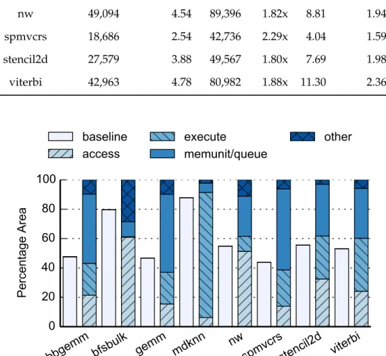
2.12 Area breakdown of DAE accelerators. The baseline area is shown for comparison. . . 37
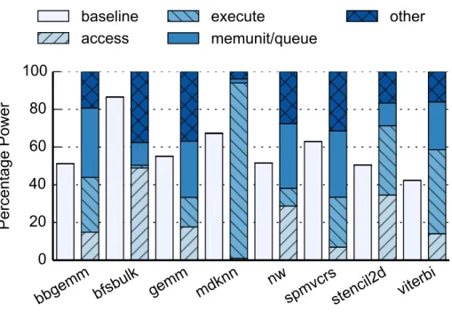
2.13 Power breakdown of DAE accelerators. The baseline power is shown for comparison. . . 39
2.14 Energy comparison. . . 40
2.15 Energy breakdown of DAE accelerators. The baseline energy is shown for comparison. If baseline energy is higher than DAE, it is annotated with a number on top of the bar. . . 41
2.16 Performance comparison when varying load queue (LQ) sizes. . 42
3.1 Continuation passing for (a) sequential composition of tasks, (b) fork-join. Downward arrows represent spawning tasks. Hori-zontal arrows represent creating successor tasks. Dotted arrows represent returning values (arguments). . . 51
3.2 Task graphs constructed using continuation passing. (a) Vector-vector add. Node labels represent the start and end indices of the sub-vectors. (b) Fibonacci. Each numbered node represents the task for fib(n). Nodes labeled S represent the successor (sum) tasks. (c) Dynamic programming. Solid arrows represent spawns along which the continuation is passed. Result values are passed along dotted arrows, with the final result sent to the continuationk. . . 52
3.3 System architecture. The accelerator is shown in the shaded box. 57 3.4 FlexArch tile. . . 59
3.6 LiteArch tile. . . 64
3.7 Accelerator design flow. . . 67
3.8 C++-based worker description for Fibonacci. . . 70
3.9 Unified parallel accelerator and software flow. . . 71
3.10 Hardware and software implementation stacks. . . 73
3.11 Accelerators performance compared to parallel software on Zed-board. . . 82
3.12 Normalized accelerator performance. The x-axis is the number of workers (PEs). The y-axis is performance normalized to a sin-gle OOO core. The horizontal bar indicates the performance of an eight-core Cilk Plus implementation. . . 88
3.13 Execution time breakdown for FlexArch accelerators. Busy: PE is actively processing a task. Wait: PE is waiting to steal a task. Steal: PE is performing task stealing. . . 90
3.14 Maximum Task Queue and P-Store Occupancy for FlexArch ac-celerators. The x-axis is the number of PEs. The y-axis is the maximum number of occupied entries in any task queue or P-store at any point of execution. . . 93
3.15 Normalized performance and energy efficiency. Energy effi-ciency is the inverse of energy consumption. Both performance and energy efficiency are normalized to the Cilk Plus implemen-tation on 8 OOO cores. Points to the right of the vertical line have better performance. Points above the horizontal line have bet-ter energy efficiency. The diagonal line represents the iso-power line. Points above the diagonal line have lower power. Points for the same benchmark are linked. Note that both axes are in log scale. . . 97
3.16 Performance when varying accelerator L1 cache size. . . 98
3.17 Performance comparison between parallel software implemen-tations. . . 99
4.1 A sequence of jobs for a task. . . 105
4.2 Execution time of H.264 decoder for three video clips at 60fps. Each point is one job (frame). . . 106
4.3 Actual execution time and execution time predicted by PID con-troller for H.264. . . 108
4.4 Operation of predictive DVFS. . . 110
4.5 Accelerator with execution time prediction-based DVFS. . . 110
4.6 Execution time prediction flow. . . 111
4.7 Control-Datapath structure of an accelerator. . . 112
4.8 Example Finite State Machine in control unit. . . 113
4.9 Predictor operation modes. . . 122
4.11 Errors of slice-based execution time prediction. The box extends from the 25% to 75%, with a line at the median. The whiskers show the range of the data. Outliers are shown as individual points. . . 130 4.12 Normalized energy and deadline misses of different DVFS
schemes. . . 130 4.13 Area, energy and execution time overhead of prediction slice. . . 131 4.14 Normalized energy and deadline when overhead is removed. . . 132 4.15 Normalized energy and deadline misses with voltage boosting. . 133 4.16 Normalized energy and deadline misses when varying
dead-lines (averaged across all benchmarks). . . 134 4.17 Normalized energy and deadline misses for FPGA-based
accel-erators. . . 135 4.18 Area, energy and execution time overhead of prediction slice for
FPGA accelerators. . . 136 4.19 Comparison of prediction errors and deadline misses between
slicing at RTL and HLS level. . . 137 4.20 Comparison of area, energy and execution time overhead
CHAPTER 1
INTRODUCTION
As technology scaling slows down and only provides diminishing improve-ments in general-purpose processor performance, computing systems are in-creasingly relying on customized accelerators to meet the performance and en-ergy efficiency requirements of emerging applications. For example, today’s mobile SoCs rely on accelerators to perform compute-intensive tasks such as multimedia processing and face recognition [10,89], and datacenters are starting to deploy FPGA and ASIC accelerators for applications such as web search [87] and machine learning [56]. This trend is expected to continue and future systems will contain more specialized accelerators. However, the traditional hardware-oriented accelerator design methodology is costly and inefficient be-cause it requires significant manual effort in the design process. As a result, only the most widely used applications today are able to amortize the high de-velopment cost and benefit from accelerators. This dede-velopment model is un-sustainable in the future where a wide variety of accelerators are expected to be designed for a large number of applications. To address this problem, the development cost of accelerators must be drastically reduced, which calls for more productive design methodologies that can createhigh-quality accelerators withlow manual effort.
1.1
Background
In the past five decades, the landscape of semiconductor technology scaling has been largely governed by two laws: Moore’s law [71] and Dennard scaling [38].
onto an integrated circuit doubles with each technology generation. Dennard scaling states that when voltages are scaled along with transistor dimensions, metal-oxide semiconductor field-effect transistors (MOSFETs) can be made to switch faster, and at the same time, consume less power. For decades, computer architects have successfully harnessed architecture scaling, enabled by Moore’s law, and frequency scaling, enabled by Dennard scaling, to design microproces-sors with exponentially higher clock frequencies and new architecture features, achieving tremendous growth in performance and energy efficiency.
Unfortunately, technology scaling is becoming increasingly more difficult today. Dennard scaling started to break down around the mid-2000s, when it became clear that scaling supply voltage proportionally with transistor feature size is no longer feasible due to the difficulties in scaling the threshold voltage. As a result, continuing to scale transistor frequency would lead to drastically increased power density, which is impractical due to cooling constraints. This is known as thepower wall, which effectively ended the exponential increase of microprocessor clock frequency, and prompted the industry to shift to multi-core architectures. Moore’s law has significantly slowed down too: as transistor feature sizes approach physical limits, developing new technology generations is becoming increasingly difficult and costly. It is likely that in the near future, we will enter an era without Moore’s law or Dennard scaling. As a result, con-tinuing to scale the number of cores on a chip is unsustainable without Moore’s law. To make things worse, not all cores can be powered on at the same time due to power limits [39]. As a result, computer architects have to turn to other approaches to continue improving performance and energy efficiency. Among many candidates, accelerators are emerging as a promising solution. Accelera-tors trade off generality for efficiency by specializing the hardware for a reduced
Netlist System RTL Bitstream Layout Chip Architecture Design Hardware Design Logic Synthesis Algorithm Architecture RTL Integration Algorithm Architecture RTL Place Route Fabrication • • • • • • ASIC FPGA
Figure 1.1: Current accelerator design flow.
set of applications. Accelerators have been shown to deliver orders of mag-nitude better performance and energy efficiency compared to general-purpose processors [24, 56], and offer a promising way going forward in the absence of technology scaling benefits.
1.2
Design Complexity of Accelerators
Accelerators achieve efficiency through specialization. By focusing on a reduced set of applications (often just one), the data path and memory circuitry of an ac-celerator can be specialized and optimized, thus achieving better performance and/or energy efficiency. It has been shown that many of the optimizations in accelerators are algorithm-specific [50], which means that different applications will need to use different accelerators to in order to achieve the best efficiency. For this reason, we focus on accelerators that are custom designed for their tar-get applications in this thesis. Future systems need to use an increasing number of accelerators for various applications in order to sustain the growth in perfor-mance and energy efficiency. This trend can already be seen in the mobile space, where each generation of SoCs integrates more accelerators [27, 102].
Unfortunately, an increasing number of accelerators creates a design com-plexity problem. Most of today’s accelerators are designed using a low-level hardware design methodology that involves significant manual effort and in-curs high non-recurring engineering (NRE) costs per accelerator. As a result, the design complexity and cost grows quickly with the number of accelerators, which limits the number of accelerators that can be economically designed, and thus limiting the number of applications that can be accelerated. We call this problem the design complexity wall. Just as the power wall ended microproces-sor’s frequency increase, the design complexity wall may end the growth of accelerators too. Figure 1.1 shows the major steps of today’s accelerator design flow. For each algorithm that needs to be accelerated, designers first conceive the architecture of the accelerator, and then perform hardware design by writ-ing register-transfer-level (RTL) descriptions of the accelerators uswrit-ing hardware description languages such as Verilog or VHDL, or using software tools to gen-erate the RTL. Then the designers integrate the RTL descriptions of the accel-erators into a system which may contain other components such as general-purpose processor cores and memory controllers, and then run the standard synthesis, place and route tools to obtain the physical layout for ASIC imple-mentation, or the bitstream for FPGA implementation. During each step of the process, designers also need to test the accelerators and repeat the step until the design meets the performance and functionality specifications. The poor productivity of this flow, especially the process of converting each algorithm to efficient hardware architectures and RTL, is a major contributor to the design complexity problem. Studies have shown that designing accelerators using this flow often takes months, which can be an order of magnitude longer compared to software implementations [36, 65, 109]. We observe that one primary reason
for the low productivity is the high manual effort involved in the design pro-cess. Today’s accelerator design methodologies require designers to manually describe the low-level details of an accelerator’s operations statically at design time. In contrast, modern computer architectures and system software support many dynamic features that automatically adapts to application behavior at runtime for improved programmer productivity, performance, and/or energy efficiency. For example, dynamic scheduling, automatically managed memory hierarchy, and data prefetching free programmers from needing to manually manage instruction scheduling and data movements. Power management tech-niques such as dynamic frequency and voltage scaling (DVFS) adaptively adjust to application behavior to achieve energy savings. Task-based parallel program-ming frameworks provide abstractions for easily expressing diverse types of parallelism, and adaptively schedules the computation to allows programmers to write efficient parallel programs without needing to worry about low-level details.
Solving the design complexity problem would require hardware design to be much more productive, and more like modern software design. Just like high-level languages, reusable libraries, and optimizing compilers freed soft-ware programmers from needing to write low-level assembly code and dras-tically improved productivity, today’s accelerator design also needs high-level abstractions, reusable architectures, and automated design frameworks in order to be productive and efficient. In addition, just as optimizing compilers needed to generate code with comparable quality to hand-written assembly, high-level accelerator design frameworks also need to generate high-quality hardware in order to be widely used.
1.3
Thesis Contributions and Organization
This thesis proposes to address the design complexity problem with archi-tectural frameworks that combine novel accelerator architectures with automated design and optimization frameworks to enable designing high-performance and energy-efficient accelerators with minimal manual effort. The accelerator ar-chitectures provide high-level abstractions and reusable architecture templates that offer dynamic and adaptive features which can be applied to the design of high-quality accelerators for a wide range of applications. The automated frameworks include a structured HLS design methodology that combines the benefits of high-level synthesis and hardware generation techniques to enable designing accelerators with high productivity while retaining the flexibility of quality advantages of RTL designs. In addition, the frameworks leverage pro-gram analysis and compiler optimization techniques to enable generating op-timized accelerators with novel architectural features. Specifically, the thesis proposes three such architectural frameworks to address concrete challenges in today’s accelerator design, and achieve reduced design complexity, improved performance, and better energy efficiency.
1. The thesis proposes an architectural framework for automatically generat-ing accelerators that can effectively tolerate long, variable memory laten-cies, which improves performance and reduces design effort by removing the need to manually create data preloading logic [23]. The framework leverages architecture mechanisms such as memory prefetching and ac-cess/execute decoupling, as well as compiler analysis to generate acceler-ators that can intelligently preload data needed in the future from the main memory. The framework uses program slicing and architecture templates
together with high-level synthesis to enable generating fully synthesizable accelerators automatically from high-level languages.
2. The thesis proposes an architectural framework for building parallel ac-celerators that leverages concepts from task-based parallel programming, which enables programmers to quickly create high-performance accelera-tors using familiar parallel programming paradigms, without needing to know low-level hardware design knowledge [22]. The framework uses a computation model that supports dynamic parallelism in addition to static parallelism, and includes a flexible architecture that supports dy-namic scheduling to enable mapping a wide range of parallel applications to accelerators and achieve good performance. The framework includes an architecture template and uses hardware generation to automatically generate accelerators with the proposed architecture from high-level de-scriptions. In addition, the thesis proposes a unified language that can be mapped to both software and hardware, enabling programmers to create parallel software and parallel accelerators in a unified framework.
3. The thesis proposes an architectural framework that enables accelera-tors to perform intelligent dynamic voltage and frequency scaling (DVFS) to achieve good energy-efficiency for interactive and real-time applica-tions [21]. The framework combines program analysis and machine learn-ing to train predictors that can accurately predict the computation time needed for each job, and adjust the DVFS levels to reduce the energy con-sumption. The framework automatically generates the prediction hard-ware from the RTL description of an accelerator.
frame-the framework for generating parallel accelerators that support dynamic paral-lelism, and the unified language for describing both parallel hardware and soft-ware. Chapter 4 describes the framework for generating accelerators that can perform intelligent dynamic voltage and frequency scaling. Finally, Chapter 5 summarizes related work, and Chapter 6 concludes the thesis and discusses fu-ture directions.
CHAPTER 2
MEMORY OPTIMIZATION FRAMEWORK FOR EFFICIENT DATA SUPPLY
2.1
Introduction
This chapter proposes a framework to automatically optimize hardware accel-erators and enable them to effectively hide long, variable memory latencies of an SoC memory hierarchy by preloading data in parallel to computations. The effective data preloading is achieved through hardware prefetching and design transformations to decouple memory accesses and computations. This framework is generally applicable to accelerator designs that are attached to the memory bus or the last-level cache and have their own memory access logic. This accelerator design style is widely adopted both in the industry and the re-search community [21, 24, 32, 66, 89, 113]. While the techniques proposed in this framework can be applied to any accelerator in general, the framework is de-signed to target accelerators that are generated usingHigh-Level Synthesis(HLS). HLS compiles high-level languages such as C/C++ [20, 114], OpenCL [54], or domain-specific languages [11, 58] into RTL. HLS is becoming an increasingly popular approach to design accelerators because it raises the level of abstrac-tion of hardware design, and is used in both industry designs [42] as well as hardware accelerator research [92, 98].
Unfortunately, even with HLS, data supply from memory often needs to be carefully coordinated with manual optimizations in order to achieve high per-formance in hardware accelerators. For example, today’s HLS tools assume
write explicit logic to manage the communication between DRAM and on-chip scratchpad memory. This approach requires serious manual design efforts, and the resulting management logic is accelerator-specific and not reusable for other designs. Alternatively, designers can use caches to ease communication man-agement given locality in memory accesses [8]. However, we found that caches are not sufficient to provide high performance without carefully orchestrated data supply. Unlike modern processors with expensive latency-hiding mecha-nisms such as dynamic scheduling, typical accelerators rely on a static pipeline schedule and a cache miss stalls the entire pipeline.
This framework proposed in this chapter aims to enable efficient data supply for HLS-based accelerators without manual efforts necessary today. To achieve this goal, we remove inefficiencies in today’s cache-based accelerators in two ways. First, we use a prefetch engine to remove cache misses for easy-to-predict memory accesses. The prefetch engine is general and common across accel-erators. For example, we use a stride prefetcher in our experiments. Second, to handle complex memory access patterns, we propose to decouple memory access logic of an accelerator from the main computation pipeline. For many accelerators, memory addresses of data that need to be accessed are often in-dependent of main computations and can be computed ahead to fetch data in parallel to the main computation. Thus, by decoupling the memory access logic from the computation pipeline, it can run ahead to fetch and buffer the data to be consumed by the computation pipeline. As long as the access logic runs sufficiently ahead, it can absorb cache misses without stalling the computation pipeline, this hiding memory latency. In fact, data supply in manually opti-mized accelerators relies on such decoupling and preloading. In this chapter, we show that this decoupling can be done automatically using program slicing
on a high-level accelerator design. The framework can be applied to existing high-level synthesis tools with minimal manual efforts.
While prefetching and access/execute decoupling have been studied for pro-cessing cores, we found that applying them to accelerators introduce new chal-lenges. For prefetching, unlike processing cores, accelerators do not have pro-gram counters (PCs) that can be used to easily distinguish different sources of memory accesses. In order to apply traditional prefetch algorithms, we aug-ment our accelerator generation process to automatically add additional tags.
We also found that simply decoupling memory accesses from main com-putations alone does not significantly improve the performance of acceler-ators unless independent accesses can be overlapped. The decoupled ac-cess/execute (DAE) architecture on processing cores rely on expensive out-of-order or dataflow execution to perform multiple accesses in parallel. For hardware accelerators with static pipelines, we show that simple decoupling of memory accesses through dedicated forwarding logic is sufficient to achieve good performance with minimal overhead in most cases.
In order to evaluate the effectiveness of the proposed framework, we ap-plied prefetching and access/execute decoupling to eight HLS-based accelera-tors. The experimental results show that the proposed framework can be ap-plied to accelerators with minimal manual efforts and significantly improve the performance compared to the baseline accelerator. The DAE architecture alone improved performance by 1.89x on average while the average speedup increased to 2.28x when prefetching was added. The optimizations also reduce energy consumption for many accelerators, by 15% on average.
The rest of the chapter is organized as follows. Section 2.2 provides an overview of the accelerator data supply problem and briefly discusses the pro-posed solution. Section 2.3 describes prefetching as an approach to improve accelerator data supply and a technique to enable efficient prefetching for hard-ware accelerators. Section 2.4 describes the architecture of access/execute de-coupled accelerators as well as a framework to automatically generate them from a high-level description. Section 2.5 discusses our evaluation methodol-ogy, experimental setup, and evaluation results.
2.2
Overview
2.2.1
System Architecture
Figure 2.1 shows the high-level system architecture that we assume in this chap-ter. The system is a heterogeneous SoC that consists of general-purpose process-ing engines such as processor cores and GPGPUs as well as a large number of accelerators. We consider stand-alone accelerators that are loosely-coupled to the cores and have their own memory interfaces to access main memory. A processing core configures and initiates an accelerator, then the accelerator per-forms its computation without intervention from the core. Each accelerator has its own compute pipeline and accesses memory through an on-chip cache.
Shared LLC Interconnect Memory Interface
● ● ●
Core $ GPGPU Core $ Accelerators $ Compute PipelineFigure 2.1: System architecture.
2.2.2
High-Level Synthesis
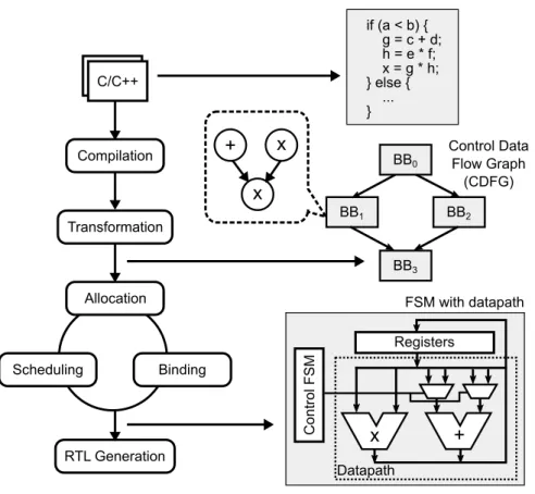
In this work, we target accelerators that are generated using High-Level Syn-thesis (HLS). Figure 2.2 shows a typical HLS flow that automatically transforms a functional description of the accelerator written in a high-level language such as C or C++ into a register-transfer level (RTL) description. To achieve this, HLS tools first transform source code into control data flow graphs (CDFG), and then perform allocation, scheduling, and binding to generate the final RTL. HLS tools usually pipeline the computation in order to achieve high performance. The pipeline is generated using a static schedule, where each operation is placed in a fixed slot determined at compile time. This approach works well if all func-tional units and memory operations have a short fixed latency. For operations with an uncertain latency, the HLS tool has to use a best guess for scheduling. For example, cache accesses are usually assumed to be a hit in order to gener-ate a compact pipeline schedule. Then, the pipeline is stalled at run-time if an access turns out to be a cache miss.
if (a < b) { g = c + d; h = e * f; x = g * h; } else { ... } + Control FSM Registers x Datapath BB0 BB1 BB2 BB3 C/C++ Compilation Transformation Allocation Scheduling Binding RTL Generation + x x Control Data Flow Graph (CDFG) FSM with datapath
Figure 2.2: High-level synthesis flow.
2.2.3
Impact of Memory Accesses on Accelerator Performance
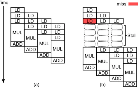
We use an example to illustrate how a long memory access latency on a cache miss can impact accelerator performance. The code in Figure 2.3 shows the inner loop of a sparse matrix vector multiplication (SpMV) accelerator. Note that the access to thevecarray is an indirect memory access that has an irregular access pattern, and is likely to miss in the cache.
An example pipeline schedule for the corresponding accelerator is shown in Figure 2.4. The pipeline has an initiation interval (II) of one, that is, a new iteration can begin execution every clock cycle in the ideal case, as illustrated in Figure 2.4(a). The three load operations in each iteration are toval,cols, and
1 for (j = begin; j < end; j++) {
2 #pragma HLS pipeline
3 Si = val[j] * vec[cols[j]];
4 sum = sum + Si;
5 }
Figure 2.3: The inner loop of sparse matrix vector multiplication.
LD LD LD MUL ADD LD LD LD MUL ADD LD LD LD MUL ADD LD LD LD MUL ADD LD LD LD MUL ADD Time LD LD LD LD LD LD MUL ADD LD MUL ADD LD LD MUL ADD LD LD LD MUL ADD Stall (a) (b) miss
Figure 2.4: Example schedule of an HLS SpMV accelerator with (a) ideal memory (b) cache that has a miss when accessingvec.
vec, respectively. Figure 2.4(b) shows an actual pipeline operation when access-ingvecin the first iteration incurs a cache miss. Since the schedule is static, the entire pipeline has to stall until the miss is resolved, even though the memory accesses of later iterations might have been hits. The stall due to a long memory access latency can have a large impact on the accelerator’s performance. For example, in Figure 2.4(b), although only one out of four iterations has a cache miss, the effective initiation interval for the four iterations is increased from one to two, essentially lowering the throughput by half. The impact can be even larger for accelerators with deeper pipelines where one cache miss can
poten-tially stall many more operations than what is shown in the example.
Our experimental results on a set of HLS-based hardware accelerators sug-gest that the performance loss due to long memory accesses is significant. There exists a large performance gap between accelerators with ideal memory (1-cycle) and a realistic cache-based memory hierarchy. This work aims to bridge this gap by developing techniques to automatically preload data for accelera-tors. An ideal preloading scheme would effectively eliminate cache misses, and allow the pipeline to run at the full throughput possible with the ideal memory.
2.2.4
Data Preloading Framework
There are a few challenges in developing a data preloading scheme to enable efficient data supply for accelerators. First, the scheme needs to accurately pre-dict future data needs of an accelerator so that data can be preloaded. Second, the prediction needs to be early enough to hide memory latency. Third, the pre-diction and memory accesses need to be decoupled from computation so that accesses and computation can happen in parallel. Fourth, all the above need to be performed automatically with minimal manual efforts.
In this work, we use two data preloading techniques to hide long memory accesses: (1) prefetching and (2) access/execute decoupling. These two tech-niques have complementary characteristics, and can both be applied with min-imal manual efforts.
Hardware prefetchers predict likely memory addresses to be accessed in the future by observing a sequence of memory accesses at run-time. For
exam-ple, a stride prefetcher is widely used to detect and preload streaming mem-ory accesses with a fixed stride. In our example, simple strided accesses such asval[j]andcols[j] can easily be detected and preloaded by a hardware prefetch engine. Moreover, the prefetch engine is inherently decoupled from ac-celerators and can perform multiple prefetching operations in parallel. On the other hand, on-line prefetching often cannot accurately predict complex mem-ory access patterns such as the indirect accesses (vec[cols[j]]) in our exam-ple.
For difficult-to-predict memory accesses, we use decoupled access/execute (DAE) architecture. In this approach, we observe that program slicing tech-niques can be used to automatically separate parts that are necessary to com-pute addresses for memory accesses (access part) from the rest that performs main computations (execute part). Then, the access part can run ahead of the execute part to preload data. In a sense, the DAE approach provides a per-fectly accurate predictor for future memory accesses. However, decoupling and providing early predictions can be more difficult in the DAE architecture compared to prefetching. In DAE, address generations must be exact (binding) unlike prefetching whose predictions may be incorrect (non-binding). Also, in certain cases, it may be difficult to decouple the access and execute parts due to dependencies. Table 2.1 summarizes the characteristics of prefetching and DAE in terms exactness in address generation, accuracy, and timeliness.
Our experiments show that prefetching and DAE can complement each other. DAE enables accurate preloading of memory addresses when possible. Prefetching provides speculative preloading for simple access patterns when DAE cannot generate exact addresses early enough.
Table 2.1: Comparison of prefetching and DAE.
Binding Accuracy Timeliness Prefetch No Good when regular Good
DAE Yes Good Depends
2.3
Prefetching
As we mentioned in the previous section, hardware prefetchers observe the memory address stream and predict the addresses that are likely to be refer-enced in the future. In most cases, just looking at a global address stream is not enough to make good predictions, as the global stream is usually a mix-ture of multiple data streams with different strides as well as irregular accesses, making it difficult to learn the access pattern and make predictions. Thus, most hardware prefetchers perform stream localization to separate a global address stream into multiple local address streams that can be learned and predicted ef-fectively, and to exclude irregular accesses with poor predictability. Since most hardware prefetchers are designed for general-purpose processing cores, they often use the program counter (PC) of load and store instructions as a hint for stream localization [13, 75], with the intuition that different streams come from different instructions in the program. In addition, the PC is also used for other purposes such as spatial correlation prediction [103] to improve the accuracy of prefetching. Hardware accelerators, on the other hand, usually do not have a PC. Thus, traditional hardware prefetchers that rely on a PC would not be effective when used naively with hardware accelerators.
type len addr data
type len addr data tag
Original Memory Request Message Format
Modified Memory Request Message Format
Figure 2.5: Modified memory request message format.
indicate which memory instruction in a program a memory access comes from. If we replace the PC with a unique identifier for each memory instruction, the prefetcher would work equally well as the identifier provides the same amount of information for stream localization. Thus, we propose to tag each memory access operation in a hardware accelerator with a unique identifier that is sent to a prefetch engine in place of the PC for each memory access. In our implemen-tation, we modified the memory request message format of the accelerators to include a tag field, as shown in Figure 2.5. To generate the tags, we add an extra pass to the HLS compiler frontend, which traverses all basic blocks in the code, and tags each memory operation with a unique identifier that emulates a PC. The pseudo-code of the pass is shown in Algorithm 1. Using the tag, features such as PC-based stream localization would work correctly, and the hardware prefetcher is able to effectively prefetch memory addresses of hardware acceler-ators.
2.4
Decoupled Access/Execute
While hardware prefetchers are effective in prefetching regular memory ac-cesses, they work less well for complex access patterns or short streams that do
Algorithm 1: Generate tags for memory accesses
1: procedureGENERATETAGS 2: t ←0
3: for allbasic blocksdo
4: for alloperations in the basic blockdo 5: ifop.type =loadorop.type =storethen
6: op.tag← t 7: t ←t+4 8: end if 9: end for 10: end for 11: end procedure
not trigger hardware prefetching. The fundamental limit of hardware prefetch-ers is the lack of semantic information about the computation. Previous stud-ies have proposed various techniques to employ semantic information to en-able more accurate prefetching for software programs. For example, software prefetching [72] allows programmers or compilers to embed prefetch instruc-tions into the code, which provide hints to the hardware about the addresses to be accessed in the future. Helper thread [35] and runahead execution [73] pre-execute a part of the program or a specially crafted program slice to bring data into the cache. All these techniques rely on the assumption that memory ad-dresses can often be computed well ahead of when the data are needed. Decou-pled access/execute (DAE) [101] materializes this assumption to a full extent by allowing the memory access part, where memory addresses are computed and data accesses are performed, to run ahead of the execute part, where data are
Time LD miss LD LD LDLD LD LD LD LD LDLD LD Stall
Figure 2.6: Example schedule of the access part of a decoupled SpMV ac-celerator when there is a cache miss.
consumed. In a typical access/execute decoupled architecture, the access part manages all communications with the memory and supplies data to the execute part; the execute part does not have a memory interface.
A key requirement for achieving performance improvements with DAE is that the access part in the decoupled architecture must run faster than the non-decoupled architecture, otherwise the performance is limited by the access part. However, in highly pipelined accelerators, this is unlikely true. Figure 2.6 shows an example schedule of the access part of a decoupled SpMV accelerator where the same miss occurs as in the non-decoupled version shown in Figure 2.4. The miss has the same performance impact on the access part as in the non-decoupled version. Thus, simply dividing the accelerator pipeline into access and execute parts is unlikely to improve performance significantly when the access part has the same rigid pipeline that cannot tolerate memory latencies. Allowing the access pipeline to tolerate cache misses is a key challenge in de-signing the DAE accelerator architecture.
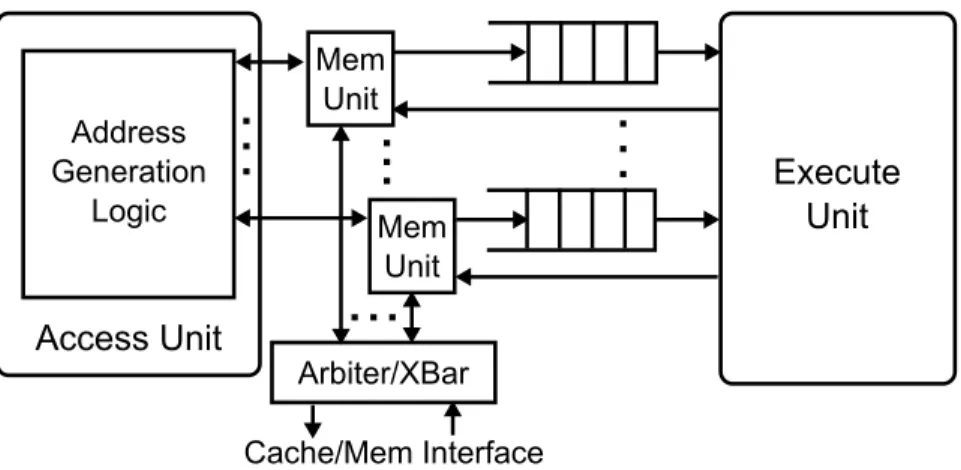
Access Unit Execute Unit Cache/Mem Interface Arbiter/XBar Address Generation Logic Mem Unit Mem Unit
Figure 2.7: Architecture of access/execute decoupled accelerators.
accelerator, consisting of the Access Unit, Execute Unit, Memory Units, and de-coupling queues. A visible difference from classic access/execute decoupled ar-chitectures is the added memory units, which is a proxy through which memory accesses are performed. Later we will show that this is necessary for tolerating the memory latency. The access unit generates memory addresses and request types, and then sends them to the memory unit to be forwarded to memory. For load operations, once responses come back, the memory unit enqueues the data into the Load Queue (LQ) to be read by the execute unit. For store op-erations, the memory unit combines the address from the access unit and data from the execute unit, and then sends the request to memory. An access/execute decoupled accelerator can have multiple memory units, which share the cache interface.
2.4.1
Access Unit
In a simple DAE accelerator implementation, the access unit is responsible for address generation, handling memory requests/responses, and forward-ing data to the execute unit, all in a sforward-ingle static schedule generated by the HLS tool. Among these tasks, address generation and sending out memory requests usually have a fixed latency and thus would work well under the static schedule. Handling memory responses and forwarding data, however, have variable latencies depending on when the response comes back from memory. This has two implications. First, they cannot be executed efficiently under the static schedule generated by HLS. Second, they may stall address generation and sending out requests for other independent accesses. To address this prob-lem, we propose to decouple memory response handling and data forwarding from address generation and sending out requests. Specifically, we delegate these tasks to the memory unit, which handles them independently, decoupled from the access unit.
The result of a load operation can either be used by the execute unit for data computation or by the access unit for address computation. In the first case, the access unit is not involved in handling the load result. This type of load opera-tions are called terminal loads [49]. In the second case, however, the access unit would need to wait for the load result and thus its pipeline could be stalled if the load is a miss. One way to enable the access unit to continue to perform independent operations is to employ an out-of-order core as the access unit, or use dataflow execution for memory accesses [51]. Though these approaches can achieve higher performance, we choose not to employ them because we observe that the load dependency chains in many accelerators are short. In fact, a large
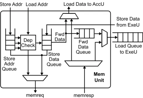
Load Queue to ExeU Mem Unit Dep Check memreq memresp Store Addr Store Data from ExeU Load Addr Store Addr Queue Store Data Queue Fwd Data Queue Load Data to AccU
Fwd Data
Figure 2.8: Hardware structure of the memory unit.
portion of load operations are terminal loads. This is because many accelerators mostly perform parallel operations, instead of serial operations through mem-ory such as pointer chasing. Decoupling just terminal loads, i.e. the last node of a load dependency chain, provides most of the benefits with a low cost. Hence, our architecture would work reasonably well for short memory dependency chains, and we trade off the ability to handle long chains for low hardware complexity.
2.4.2
Memory Units
Figure 2.8 shows the hardware structure of the memory unit. It mainly consists of load queue, store queue, forward data queue, dependency checking logic, and memory request/response routing logic.
sent to memory, either because the store data have not been computed yet, or because it is waiting for access to the memory interface. The Store Data Queue (SDQ) buffers store data from the execute unit. The head entries of SAQ and SDQ are paired to form a store request to be sent to memory.
Each load request from the access unit contains a dest field indicating whether the result is used by the access unit or the execute unit. The field is kept in the corresponding response to the request. When the memory unit re-ceives a load request, it checks whether there is an entry in the SAQ matching the store address. If there is a match, the load waits until the corresponding entry in the SDQ is valid, and data is forwarded from the SDQ to either the For-ward Data Queue (FwdQ) or the access unit, depending on whether the load operation is a terminal load or not. If there is no match, the load request is sent to the memory. The load and store requests share the memory port. Load requests are given priority over stores to reduce load latency.
The Load Queue (LQ) contains data to be forwarded to the execute unit. When a load response returns from memory, itsdestfield is inspected to route the response data to the LQ, the access unit, or both. Because the execute unit consumes data from memory in a program order, the LQ entries are reserved and maintained in the request order. For example, responses from the memory and the Forward Data Queue are placed in the LQ in the program order. The memory unit supports multiple in-flight requests. If the cache returns responses out-of-order, the LQ is used to reorder and return them in order.
2.4.3
Execute Unit
The execute unit is generated using HLS from the execute slice, and mainly consists of the data computation pipeline.
2.4.4
Deadlock Avoidance
There exist two possible deadlock situations in the proposed access/execute de-coupled architecture. Here we describe them and discuss how to prevent them.
Pipelining-Induced Deadlocks: A deadlock may occur when accelerator pipeline interacts with a store queue of insufficient size. Suppose the exe-cute unit pipeline has latency Land initiation interval I I, it needs to consume
N = dL/I Ie inputs before producing the first output. If the store queue size is less than N, it may fill up and block the access pipeline. Because the exe-cute pipeline depends on the access pipeline for data supply, it also blocks and the accelerator deadlocks. The deadlock occurs because pipelines generated by most HLS tools do not support flushing by default. That is, a blocking oper-ation stalls the entire pipeline, not just subsequent iteroper-ations. This restriction enables HLS tools to generate simple pipelines without complex control logic and buffering, but causes deadlocks in this situation.
Pipeline synthesis techniques that support flushing [37] can be used to avoid this deadlock. If the HLS tool does not support flushing, another approach is to ensure that size of the SAQ is larger than N = dL/I Ie, so that it would not become full before the execute pipeline produces the first output. Often the SAQ size required for performance reasons is already greater than N, then no
additional changes are needed in this case.
Deadlock Due to Full Load/Store Queues: A deadlock can occur when the queues are full and form a circular dependency. For example, a load response returns from memory when the load queue and store queue are both full, and the memory system cannot accept another request because it has reached the maximum number of in-flight requests. In this situation, the load queue cannot be drained because the execute unit is stalled trying to write to the full store queue, which is waiting for the memory system, which in turn is waiting for the load queue. This creates a circular dependency, causing a deadlock. This deadlock can be avoided by ensuring that not all queues can become full at the same time. Specifically, we track the number of in-flight load operations and free entries in the load queue, and delay issuing a load if the response would cause the load queue to become full.
2.4.5
Customization of Memory Units
The memory unit design described in Section 2.4.2 can be customized to fit the needs of a particular accelerator, providing just enough resources and features but not more. The sizes of various queue structures can be adjusted to fit the accelerator’s memory characteristics. For example, if the accelerator rarely per-forms stores, sizing down the store queue would help save area and energy. If a certain feature is unused by an accelerator or does not help too much, it can be removed. For example, if a memory port is read-only, the memory unit can be made much simpler by removing any store-related features such as store queue and dependency checking logic. As another example, store to load forwarding
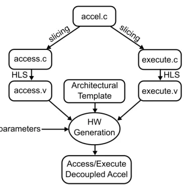
accel.c Architectural Template HW Generation access.v execute.v Access/Execute Decoupled Accel slicing slicing parameters access.c execute.c HLS HLS
Figure 2.9: High-level flow of decoupled access/execute accelerator gen-eration.
can be removed if the accelerator does not need it.
2.4.6
Automated DAE Accelerator Generation
Figure 2.9 shows the high-level flow used by the framework for automatically generating accelerators with access/execute decoupling. Starting from a single source code written in a high-level language, the framework uses program slic-ing [110], which is built in modern optimizslic-ing compilers, to generate access and execute slices. To generate the access slice, the program slicing algorithm back-tracks from loads and stores in the Control Data Flow Graph (CDFG) of an ac-celerator and keeps all necessary operations for computing memory addresses, while removing others. To generate the execute slice, the algorithm backtracks
from stores and finds all operations needed to compute store values. The slicing process also performs transformations to enable decoupling. In the access slice, stores are transformed intostore addr operations, which only have address but not data. Terminal loads are identified as loads that are not in the back slice of address calculations, and are transformed into load fwdoperations which indicate that the result should be consumed by the execute slice. In the execute slice, all loads and stores are replaced with queue reads and writes. The frame-work then synthesizes the resulting access and execute slices into Verilog RTL using HLS.
The framework implements the decoupled accelerator architecture shown Figure 2.7 in as an architectural template written in a hardware generation lan-guage PyMTL [69]. The template includes RTL implementations of the compo-nents such as memory unit, queue structures, arbiters, and memory crossbars. The architectural template is designed to be fully configurable to allow cus-tomization of the modules as described in Section 2.4.5. For example, the sizes of the load and store queues, as well the architecture features can be configured.
To generate the final RTL of the accelerator, the framework elaborates the template with the parameters specified by the designer, and combines it with the access and execute slices to output the RTL of the access/execute decoupled accelerator.
2.5
Evaluation
In this section, we present the evaluation results for the proposed data supply framework for accelerators. We first discuss our evaluation methodology and
experimental setup. Then, we show the performance, area, and energy results.
2.5.1
Methodology
We use an integrated evaluation methodology that combines cycle-level, register-transfer-level, and gate-level modeling.
Cycle-level modelingis used to model the performance of the system com-ponents including caches, interconnect, memory controller, and main memory. We use gem5 [15] for this purpose.
Register-transfer-level modeling is used to accurately model the perfor-mance of hardware accelerators. Vivado HLS 2015.2 is used to synthesize a C-based description of the accelerators into Verilog. For DAE accelerators, RTL of the memory unit and queue structures are generated from the architectural template. Verilator [3] is used for RTL simulation. We integrated Verilator with gem5 for co-simulation of accelerators and system components.
Gate-level modeling is used to build accurate area and energy models for the accelerators. We synthesized, placed and routed each accelerator using Syn-opsys Design Compiler and IC Compiler with the TSMC 65nm standard cell library to obtain area numbers. Design Compiler automatically inserts clock gating logic for all designs. Power and energy analysis were performed using Synopsys PrimeTime PX with the switch activity factors obtained from simula-tions of the place and routed netlist.
Table 2.2: Summary of benchmarks.
Benchmark Description
bbgemm Blocked matrix multiplication bfsbulk Breadth-first search
gemm Dense matrix multiplication
mdknn Molecular dynamics (K-nearest neighbor) nw Needleman-Wunsch algorithm
spmvcrs Sparse matrix vector multiplication stencil2d 2D stencil computation
viterbi Viterbi algorithm
2.5.2
Experimental Setup
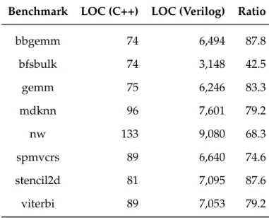
We use a set of eight benchmark accelerators adapted from MachSuite [92] in our experiments. Table 2.2 summarizes the accelerators. For each benchmark, we use the framework to generate the Verilog RTL of the accelerator with DAE and prefetching from a C++ source code. Each accelerator has a private L1 cache connected to the DRAM controller through the system bus. For prefetching, we use a stride hardware prefetcher. Table 2.3 compares the lines of code between the C++ source code and the generated Verilog RTL. The results demonstrate that the framework is able to generate high-quality accelerators from a small amount of high-level code.
Table 2.4 shows the detailed experiment parameters. We compare the fol-lowing schemes:
Table 2.3: Lines of code (LOC) comparison between the input to the frame-work (C++ source code) and the generated Verilog code. Blank lines and comments are not counted.
Benchmark LOC (C++) LOC (Verilog) Ratio
bbgemm 74 6,494 87.8 bfsbulk 74 3,148 42.5 gemm 75 6,246 83.3 mdknn 96 7,601 79.2 nw 133 9,080 68.3 spmvcrs 89 6,640 74.6 stencil2d 81 7,095 87.6 viterbi 89 7,053 79.2
Table 2.4: Experiment parameters.
Technology 65nm
Frequency 500MHz
DAE MemUnit 16-entry LQ, 8-entry SQ
Cache 16KB / 2-way / 32B line size / 1 cycle latency / 4 MSHRs Prefecher Stride prefetcher, degree=8
DRAM Single-channel 32-bit LPDDR3-1600, 6.4GB/s BW
2. Stride has the stride prefetcher enabled but not DAE. The memory ac-cesses are tagged to facilitate prefetching.
3. DAE is the access/execute decoupled implementation, but without the stride prefetcher.
2.5.3
Baseline Validation
HLS-based accelerators have a large design space. Depending on the parame-ters used, the same accelerator can be synthesized to have different area, per-formance, and power. We use the same set of parameters when synthesizing the baseline and DAE versions to exclude the possibility that the improvement comes from different synthesis parameters. To ensure that the improvement is not from poorly optimized baseline, we apply most HLS optimizations includ-ing pipelininclud-ing and unrollinclud-ing so that baseline accelerators have best performance within the system-level constraints (such as the number of memory ports or memory bandwidth).
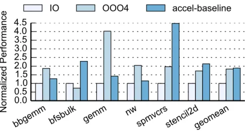
To validate the performance of the baseline, we simulated the performance of functionally equivalent software implementations of these accelerators. Fig-ure 2.10 shows the performance comparison between in-order, 4-wide out-of-order processors, and the baseline accelerators. Note thatmdknnandviterbi are not included because we use custom-precision fixed-point arithmetic in their implementations, which would be inefficient to emulate in software on proces-sors. On average, the performance of the baseline accelerators is about 2x of an in-order processor, and is comparable to an out-of-order processor. These numbers are roughly in line with previous studies [43, 108]. The performance of the baseline accelerators is mainly limited by the memory bottleneck. We will show that with the proposed techniques to enable efficient data supply, the accelerators could achieve much higher performance.
bbgemm bfsbulk gemm
nw
spmvcrsstencil2dgeomean
0.0
0.5
1.0
1.5
2.0
2.5
3.0
3.5
4.0
4.5
Normalized Performance
IO
OOO4
accel-baseline
Figure 2.10: Comparison of baseline accelerators performance with pro-cessors.
2.5.4
Performance Results
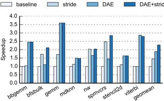
Figure 2.11 compares the performance of the proposed optimization schemes normalized to the baseline accelerator. Overall, the stride prefetcher with mem-ory access tags improves the performance by 45% on average over the baseline. DAE alone achieves an average speedup of 1.89x, while DAE combined with stride prefetching achieves a 2.28x speedup.
Comparing stride prefetching and DAE, DAE usually achieves higher per-formance due to decoupling and having more precise knowledge about the ad-dresses to be accessed next. One such case is when the access pattern is irreg-ular, but the addresses can be computed early. For example, mdknncomputes the force between a molecule and its N nearest neighbors. The access pattern is highly irregular because the addresses of the N neighbors in memory usually do not have a pattern. However, the addresses can be computed early because the indices of these N neighbors are known. Hence, the access unit can send out
bbgemmbfsbulk gemm mdknn
nw
spmvcrsstencil2d viterbi
geomean
0.0
0.5
1.0
1.5
2.0
2.5
3.0
3.5
4.0
Speedup
baseline
stride
DAE
DAE+stride
Figure 2.11: Performance of the proposed schemes normalized to the base-line accelerator.
load requests early to hide memory latency. In contrast, the stride prefetcher is unable to predict the addresses and thus unable to prefetch them.
DAE also has advantages when the accesses consist of regular but short streams. One example isviterbi. The stride prefetcher needs warm-up, thus is too late in sending out prefetch requests. It also prefetches beyond the end of the stream before realizing the stream has ended, wasting memory bandwidth and causing cache pollution. In contrast, DAE has precise information about when the stream begins and ends, thus is able to preload data effectively.
There are some cases where prefetching is more effective than DAE. For ex-ample, bfsbulk performs a graph traversal, which is dominated by memory accesses with dependencies. As a result, the access unit in the decoupled ar-chitecture is not able to pre-calculate the addresses. Prefetching, on the other