A Graph Based Requirements Clustering
Approach for Component Selection
Muhammad Ali Khan
aand Sajjad Mahmood
bCollege of Applied and Supporting Studies
a, Information and Computer Science Department
bKing Fahd University of Petroleum and Minerals
Dhahran 31261, Saudi Arabia
[email protected]
a, [email protected]
b✦
Abstract
In recent years, Component Based System (CBS) development has found widespread application, particularly in the domain of engineering software where it is often necessary to adapt and integrate existing software tools to handle new problems. The ability to identify suitable components that match system requirements is fundamental to CBS success. To date, CBS selection techniques often make an ideal assumption that there is one-to-one mapping between requirements and components. In reality, components are usually designed for general purposes and provide a range of features that can be adapted to meet the needs of a CBS. This implies that a component can potentially match more than one functionality of a CBS. On the other hand, system requirements are usually not independent of each other and a component selection process needs to consider the dependencies between system goals. Furthermore, the existing component selection methodologies usually provide a single solution for the component selection problem, thus limiting the options available to a CBS developer. In this paper, we present a component selection process that uses a signed graph to model interdependencies of CBS-to-be needs and groups related goals into clusters, based on the usage, non-functional and threat dependencies. Subsequently, the matching index of each cluster of related goals is used as a criterion to identify a portfolio of candidate components for a CBS, providing multiple solutions for the component selection problem whenever possible. The component selection process helps a developer to elicit stakeholder needs, analyze their interdependencies and select components for a CBS. We also present application of our approach to a Meeting Scheduling System (MSS) and a Construction Management System (CMS).
Index Terms
Component based software system, software component selection, signed graph clustering, matching index.
1
I
NTRODUCTIONOver the last couple of decades, the widespread use of software has placed new expectations on the software industry [1] and there is an ever growing push towards software reuse. CBS development is
an approach that aims to move the software industry away from developing each system from scratch. It focuses on integrating existing components to build a software system, with the potential benefits of reducing development time and delivering quality system by using quality components. Due to these advantages, CBS development has been utilized in a variety of engineering applications such as computer-aided design and manufacturing [2], biomedical modeling [3], finite element software [4] and the list keeps growing. The success of a CBS project requires a collaborative process in which both system stakeholders and candidate components balance the conflicting interests between what is needed and what is available [5], [6]. This collaborative process needs to focus on negotiating individual interests during the component selection phase of a CBS. In this paper, we adopt Szyperski’s definition of a component [7]: ‘A software component is a unit of composition with contractually specified interfaces and explicit context dependencies only. A software component can be deployed independently and is subject to composition by third parties’.
Recent research [8], [9] shows that CBS success depends on the ability to identify suitable components. Inappropriate component selection can lead to adverse affects such as shortlisting components that barely fulfill the needed functionality or introduction of extra costs in integration and maintenance phases [10]. The component selection process is further complicated by the fact that individual components usually provide fixed capabilities and it may not be possible to satisfy all system needs by the available components. On the other hand, components can sometimes provide additional features that may not be needed (or even desirable) in a given system. Furthermore, component selection is usually carried out by dealing with unstructured information on the web [11], [12], which makes detailed evaluation of all possible candidate components highly costly and impractical.
In line with traditional systems, stakeholder requirements for a CBS are usually not independent from each other and more than one requirement can collaborate to achieve certain features of a CBS. Hence, the component selection process cannot assume that there will always be one-to-one mapping between requirements and candidate components. Although consolidation of requirements into clusters, based on their interdependencies, is essential to understand such a process, it is not sufficient on its own as it may be impossible to find a suitable component to match a consolidated requirement. An assessment of the availability of matching components is therefore essential to validate the practicality of requirements clustering. We believe that the CBS selection process needs to focus on how to analyze interdependent requirements, consolidate related requirements in a meaningful way and facilitate shortlisting of compo-nents that match these consolidated requirements. Additionally, whenever possible the selection process should provide multiple solutions for the component selection problem to offer greater flexibility to a CBS developer. This implies that component selection should not be opportunistic; rather it should be carefully planned, based on requirements dependencies and availability of components.
In this paper, we present a component selection process that provides guidelines for CBS developers to consolidate related requirements into clusters and shortlist components that best match the required functionalities of a CBS. The component selection process developed in this paper consists of three phases:
(i)goal-oriented specificationwhich elicits CBS-to-be needs; (ii)dependency analysisthat focuses on analyzing the dependencies between CBS-to-be needs; and (iii)cluster analysis that organizes interdependent CBS-to-be needs into clusters and uses thematching indexto identify candidate components for a CBS.
We adopt the goal elicitation and refinement rules presented in [13], [14] for phase (i). In phase (ii), we introduce three types of goal dependencies, namely usage,non-functional andthreat dependencies based on the types of interaction between CBS goals. In phase (iii), we define thegoal dependency graph, which is a signed graph, to represent the relationship between CBS goals and modify the local optimization signed graph clustering algorithm [15] to cluster interdependent goals together while also taking into account the availability of suitable components. Signed graphs have often been used to capture positive and negative relationships in networks [15], [16], [17], [18]. Thus the signed graph representation lends itself to CBS goal analysis, as goals can interact positively or negatively with each other (see Section 5). In addition, the proposed representation and clustering method yields a list of candidate components that can be further evaluated for selection. We also present applications of our approach to Meeting Scheduling System (MSS) and Construction Management System (CMS) case studies. The main contributions of our work include:
• developing a dependency analysis technique for CBS goals, • introducing the concept of goal dependency graph,
• adapting signed graph clustering for consolidating CBS goals,
• introducing the concept of matching index to select components for a CBS, and • providing multiple candidate components for a CBS, whenever possible.
The remainder of this paper is organized as follows. Section 2 reviews related literature. In Section 3, we give an outline of our approach. Section 4 describes the goal-oriented specification while Section 5 presents the goal dependency analysis. In Section 6 we describe our clustering algorithm. Case studies are presented in Section 7 and 8. In Sections 9 and 10, we discuss some observations based on the findings of our case studies and propose directions for future work.
2
RELATED
WORK
2.1 Component Based Systems Overview
CBS development is an integration centric methodology with emphases on using pre-fabricated com-ponents to build a software application. Qureshi and Hussain [19] argued that the traditional software process models are not adequate for CBS development and pointed out the drawbacks of the existing CBS development models. They proposed a CBS development model by modifying the object oriented process model [20]. In addition to traditional waterfall model phases [21], the CBS development needs additional phases of component selection, engineering and testing; and evaluation [19]. Figure 1 gives an overview of the CBS development life cycle, adapted from [19].
The CBS development process can be divided into five main stages, namely, communication, planning, analysis and component selection, engineering and testing, and evaluation phases. The first phase, com-munication, gathers the overall objectives of the CBS-to-be. The communication phase is carried out at the start of a project to collect the basic requirements and initial use cases of the CBS-to-be. The planning phase focuses on preparing the project specification document. The project specification document is used for the feasibility and risk assessment of a CBS project.
The third phase, analysis and component selection, consist of two sub steps namely, ‘analysis’ and ‘component selection’. The ‘analysis’ sub step helps in gathering detailed requirements of a CBS. The dependencies between requirements are also analyzed in this phase of the CBS development life cycle. The ‘component selection’ sub step uses the detailed requirements to select suitable components from the components repository. The fourth phase deals with integration and testing process by focusing on adapting the selected components and writing glue-code to assemble them into a CBS. Finally, the fifth phase, evaluation, deals with customer evaluation and verification of a CBS with respect to stakeholder requirements. In this paper, we are only concerned with the ‘analysis and component selection’ phase.
Component Repository Communication Planning Analysis Component Selection
Engineering and Testing Requirements
Evaluation
2.2 Requirements Analysis and Component Selection
Requirements analysis and component selection are recognized as entwined processes that play a central role in the overall development of a CBS [1], [22]. Commercial Off-The-Shelf Components (COTS) Aware Requirements Engineering (CARE) [23] is a goal-oriented approach which highlights the importance of keeping requirements flexible as they help in finding suitable components. The CARE method aims to reduce the gap between stakeholder requirements and component features by using a knowledge base repository. The CARE proposes two main models, namely, process and product. The process model specifies the activities performed to define the system agents, goals and system architecture. The product model describes the format of the product created using the process.
Maiden and Ncube [24] presented an interactive process of requirements analysis and component evaluation. Their process uses templates to progressively refine the candidate component list to select suitable components for a CBS. The process model is used to identify system goals and specify the steps for achieving these goals, whereas the product model provides the semantics for modeling software products. For each iteration, the software development team acquires requirements, identifies and rejects candidate components that are not compliant with these requirements using multicriteria decision-making and explores the remaining candidates to discover possible new requirements. However, the approach lacks details on how requirements are used in the evaluation process.
COTS Based Requirements Engineering (CRE) [25] is an approach to evaluate components in terms of how well they match customer requirements. The CRE approach also considers non-functional re-quirements to evaluate alternative components by using description of quality attributes that candidate components have to meet. Clark et al. [26] proposed an approach to identify and select components in Commercial-Off-The-Shelf (COTS) repositories. The proposed model enables a system analyst to specify functional requirements at different abstraction levels and select components. This approach also allows system analysts to define required component attributes as preferences. It aims at reducing component selection process risk by making compatibility checks between components.
Cechch and Piattini [11] developed an early evaluation method for the suitability of COTS. They have proposed a set of metrics to quantify the suitability of a component in terms of compatible, missing and additional features. Like [11], our work supports early selection of components. However, we specially concentrate on the interdependencies of CBS requirements and introduce the concept of matching index as a criterion to shortlist suitable candidate components for a CBS.
Harman [27] characterized individual components by a weight and a cost value. A component’s weight consists of customer desirability and expected revenue. Similarly, a component cost is calculated as a sum of acquisition and development costs. Finally, component selection problem is formulated in term of a series of feature selection problem based on associated weight and cost.
the component selection. Case base reasoning approach consists of four steps, namely, retrieve, reuse, revise and retain. However, the proposed approach assumes that user requirements are given as a set of keyword functionalities.
Birkmeier and Overhage [29] presented a survey on the state of the art in component identification and introduced a classification scheme to analyze the respective strengths and weaknesses of different approaches. One of the main conclusions of their survey is the need to use different common efforts from diverse areas to address the challenges associated with the complex component identification process.
2.3 Clustering Approaches
Different clustering techniques have been employed in the requirements analysis of traditional and component based systems. For example, Jain et al. [30] used a clustering algorithm to assist a system analyst in selecting suitable components for a CBS. The approach uses classes defined in a domain model. The classes with the highest number of relationships are grouped together in one cluster. The approach uses a set of heuristics for further refining the clusters and subsequently selecting components for a CBS. Similarly, Lee et al. [31] have presented a component identification algorithm that aims to achieve high cohesion and low coupling among subsystems of a CBS. The subsystems are re-organized based on cohesion and coupling values by using a clustering algorithm.
Vitharana et al. [32] presented a business strategy driven approach to design components and support the fabrication process of component development. The approach maps a set of managerial goals to architectural features for component design. The authors also present a mathematical model called Business Strategy-based Component Design (BusCod) to optimally achieve the required business strategy during the design of a component. However, the approach only considers managerial goals and not the specific system functionalities required to achieve these goals.
Various fuzzy clustering techniques have also been applied to the component selection problem. For instance, Serban, Vescan and Pop [33] developed an algorithm based on metrics and fuzzy clustering to address the component selection problem. The algorithm uses the fuzzyn-means algorithm to determine the fuzzy partition of the set of components.
Recently, Cai et al. [34] introduced a fuzzy formal concept analysis technique for identifying business components by constructing a fuzzy formal context from the business models. The fuzzy formal context is later used to build the concept lattice. Finally, the concepts are analyzed and related concepts are clustered into components. Similarly, Cui and Chae [35] presented results from a series of experiments to analyze the use of agglomerative hierarchical clustering algorithms in software re-engineering. The experiment results indicate that hierarchical clustering algorithms produce quite different clustering results for component identification and the results depend on the proposed size, coupling and cohesion criteria.
2.4 Addressing the Open Problems
Despite the interest in component based systems, a number of key questions regarding the selection of suitable components remain open. The component selection approach developed in this paper aims to address several open problems that have been recently raised in the literature. For instance, Land and Blanker [36] provide a literature survey of component selection techniques and present a meta-model to compare existing component selection techniques. The authors advocate the need of a component selection technique that is intertwined with requirements engineering and gives a level of confidence measure to be used at the evaluation and decision stage of component selection process. The approach developed in this paper does both. The component selection process starts from requirements analysis phase and uses the ‘matching index’ as a confidence measure for the selection and evaluation stages of CBS development life-cycle.
In another survey paper, Mohamed et al. [37] evaluate eighteen different component selection ap-proaches and present a set of open research questions surrounding the component selection problem. One of the main issues raised by the authors is that the current component selection approaches usually provide ‘one’ optimal solution to the component selection problem. This limits the system analyst’s participation and control over the decision making process. The component selection process developed in this paper rectifies this problem by providing multiple solutions for component selection where possible. Moreover, our work combines several benefits of the methodologies discussed in Section 2.2 and Section 2.3. For instance our approach presents a systematic way of narrowing down suitable components in large repositories (i.e. the approach by Clark et al.) based on the capabilities of available components (such as CARE), while also paying due attention to non-functional requirements (as in CRE). Furthermore, the clustering paradigm is used (like [34]) to ensure that interdependent system features are bunched together in the same component. The clustering approach developed in this paper starts from the CBS business objectives, refines them to technical goals of the system and investigates a wide variety of dependencies between these technical goals. Both functional and non-functional technical goals are considered and clustered into consolidated goals of suitable granularity such that a significant number of matching components are found in the repository.
3
METHODOLOGY AND
RESEARCH
FRAMEWORK
CBS development needs a component selection process in which the potential mismatches between CBS requirements and candidate components are analyzed together to provide a portfolio of suitable components. We believe that a component selection process needs to address three key issues: understand stakeholder’s needs, analyze interdependencies of requirements; and subsequently identify a group of suitable components that best match the system requirements.
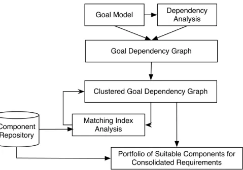
The cluster based component selection process, as shown in Figure 2, consists of three phases: namely, goal-oriented specification,dependency analysisandcluster analysis. The first phase, goal-oriented specification,
Goal Model Dependency Analysis
Goal Dependency Graph
Clustered Goal Dependency Graph
Matching Index Analysis Component
Repository
Portfolio of Suitable Components for Consolidated Requirements
Fig. 2. Cluster Based Component Selection Process Overview
uses a goal-based requirements elicitation technique [13], [14] to specify CBS requirements. The CBS requirements are classified into two abstraction levels, namely, high-level goals and concrete-level goals, based on the refinement rules defined in [14]. The second phase, dependency analysis, investigates the interplay between concrete-level goals. The third phase, cluster analysis, organizes interdependent concrete-level goals into clusters and creates consolidated goals, taking into consideration the availability of suitable components. As a result, a portfolio of candidate components is identified for each consolidated goal. The different stages of the cluster based component selection are explained in detail in Sections 4 -6.
In this paper, we follow the design science research framework [38] to present the cluster based component selection process. Hevner et al. [38] have presented seven design science research guidelines, namely, ‘design as an artifact’, ‘problem relevance’, ‘design evaluation’, ‘research contributions’, ‘research rigor’, ‘design as a search process’ and ‘communication of research’. The ‘design as an artifact’ guideline indicates that research must produce an artifact in the form of a model or method. ‘Problem relevance’ points out the need to develop technology-based solutions to relevant problems. The ‘design evaluation’ guideline suggests that the quality of a design artifact must be demonstrated via evaluation method such as case study or experiments. By ‘research contribution’ it is implied that the research should make clear contribution in the area of the design artifact. The ‘research rigor’ guideline points out that the model should use rigorous methods in the development and evaluation of a design artifact. By ‘design as search process’ it is meant that the search for an effective artifact requires utilizing available means
to reach desired ends while satisfying laws in the problem domain [38]. Finally, the ‘communication of research’ states that the research must be presented to technology-oriented as well as management-oriented audiences.
We discuss our approach with reference to these guidelines as follows:
• Design as an artifact: The main artifact of our research is the cluster based component selection process that achieves the collaboration of CBS requirements analysis and component selection. The cluster based component selection process uses the goal-oriented specification technique to elicit CBS requirements. The dependency analysis is applied to analyze the relationships between CBS requirements and finally cluster analysis is used to consolidate related requirements and select components for a CBS.
• Problem Relevance:Our research problem is highly relevant to the field of software engineering. First of all, the selection of appropriate components is critical to CBS success [3], [8], [9], [11]. Furthermore, component selection should be a collaborative process whereby both stakeholders and candidate components balance the conflicting interests of what is needed and what is available [5], [6]. As discussed in Section 2.4, researchers have highlighted the need for a component selection technique that is intertwined with requirements analysis [36], and identifies multiple candidate components [37] that match system requirements. The technique developed in this paper is aimed at fulfilling these needs. Hence, the problem of component selection, based on a thorough requirements analysis, addressed in this paper is an important problem in software industry.
• Design Evaluation:The component selection method presented in this paper is evaluated using two real-life case studies, namely, meeting scheduling system and construction management system. In Sections 7 and 8, we present the two case studies and discuss our component selection approach in detail. Furthermore, in Section 9, we discuss some observations based on the findings of the two case studies.
• Research Contribution: The main research contributions of our work are (1) development of a de-pendency analysis technique for CBS goals, (2) introduction of the concept of goal dede-pendency graph, (3) adapting signed graph clustering for consolidating CBS goals, (4) introducing the concept of matching index to select suitable components for a CBS, and (5) providing multiple candidate components for a CBS, whenever possible. All of these contributions have been demonstrated using the two case studies. Our cluster based component selection process addresses important research gaps identified in the literature (see [36], [37]) by helping system analysts to model interdependences of CBS requirements and facilitating the selection of a portfolio of candidate components that satisfy system requirements.
• Research Rigor: In this paper, we present a component selection process that uses a signed graph to model interdependencies of CBS-to-be needs and groups related goals into clusters, based on
the usage, non-functional and threat dependencies. The CBS-to-be needs are elicited using a well-established goal-oriented approach [13], [14], [39] and they are grouped into clusters using a local optimization signed graph clustering algorithm [15], [16], [17], [18] that is mathematically sound and has a long history. Hence, this research draws from a clearly defined and tested base of requirements literature and signed graphed clustering techniques.
• Design as a Search Process:The design presented in this paper consists of an iterative search for the best trade-off between CBS requirements dependencies and the availability of components. The process developed in this paper satisfies the commonly accepted laws and practices of software engineering; in fact it draws heavily from them (see the previous item). We present a heuristic approach to select components from large repositories that match CBS requirements and verify its usefulness by means of two case studies.
• Communication of Research: The main audience of this paper is CBS analysts who are familiar with goal-oriented requirements process and graph based clustering approaches. However, since the stake-holder requirements play a central role in our approach, there is strong motivation for managerial audience to adopt our approach. We further show that tools (like pajek) are readily available, with enough documentation for non-technical personnel, to understand and benefit from our approach. Moreover, the successful application of our methodology to two case studies makes it more interesting from a commercial point of view.
4
G
OAL-O
RIENTEDS
PECIFICATION ANDM
ODELCBS development needs a flexible requirements specification technique [5] that provides an opportunity for a system analyst to shortlist candidate components that either completely or partially provide the desired functionalities. Flexibility of CBS requirements is especially important for the component selection process as it increases the probability of finding closely matched components [40]. Goal-driven techniques [13], [14], [39] have been used for CBS requirements analysis because they inherently support defining the granularity of goals at different levels of abstraction. For example, Alves and Finkelstein [5] applied the concepts of goal modeling to elicit stakeholder’s needs and investigate requirements conflicts in a CBS. Similarly, Mohamed et al. [41] used a goal-driven approach to define strategic and technical goals for the component selection process. In this paper, we adopt Lamsweerde’s definition of a goal [14]: ‘. . . an objective the composed system should meet. The goals can be stated at different levels of abstraction ranging from high-level strategic objectives of the organization to low-level finer-grained goals stating technical objectives related to system design options’.
In this paper, we adopt goal elicitation approach presented in [14]. We classify CBS requirements into two refinement levels, namely, High-Level Goal (HLG) and Concrete-Level Goal (CLG). An HLG represents CBS requirements that contribute to achieve business objectives but are not detailed enough to be directly used for component selection and evaluation. For example, in the Meeting Scheduling System
(MSS) case study discussed in Section 7, ‘convenient meeting scheduled from request’ is a high-level goal which contributes to achieve the ‘effective meeting scheduling’ business objective but needs refinement to sub-goals that can be directly used to identify suitable components from a repository. On the other hand, a CLG represents a finer-grained goal that can be directly used for component selection. For example, ‘constraints request’ is a concrete-level goal, refined from ‘convenient meeting scheduled from request’, that can be directly used to find suitable components from a repository.
We further classify the CLGs into two types, namely, functional CLGs and non-functional CLGs. A functional CLG specifies the intended system behavior [14]. For example, ‘constraints requested’ is a functional CLG that prescribes that constraints are requested from participants of a meeting. A non-functional CLG represents preferences among alternative non-functional behaviors. Every non-non-functional CLG is associated with a single functional CLG and influences the solution (for example, the choice of a candidate component) for the corresponding functional CLG. For example, ‘minimum interaction with participants’ is a non-functional CLG, associated with the functional CLG ‘constraints entered’, that has a range of fulfillment degrees for different alternative solutions for constraint input. It is important to note that in our approach a non-functional CLG cannot be associated with more than one functional CLG as it may lead to misleading solutions in the clustering phase.
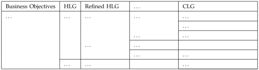
In this paper, we use the goal specification methodology [14] to elicit CBS requirements. CBS require-ments specification starts with the selection of the overall business objective of the system. The business objective is refined into high-level goals that contribute to achieving it. Subsequently, each high-level goal is refined into finer-grained goals till concrete-level goals are identified. The concrete-level goals are the leaf nodes in the refinement tree whose responsibility can be assigned to a single agent. An agent [14] is a system component playing a specific role in goal satisfaction. An agent can be an existing software component or a new software component forming part of the CBS-to-be. CBS requirements are specified into hierarchical levels and the number of hierarchical levels depends on the system [14]. We refer to this refinement as the Goal Model (GM) of the CBS, as shown in Table 1. A CLG acts as a unit of analysis during dependency analysis and the clustering phases of our approach.
TABLE 1 Goal Model
Business Objectives HLG Refined HLG . . . CLG
. . . . . . . . . . . . . . . . . . . . . . .
5
DEPENDENCY
ANALYSIS
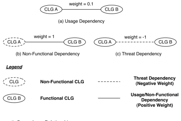
The goal model organizes high-level goals and concrete-level goals using refinement relationships. The goal model helps us in identifying the CLGs that can be used for component selection. However, the component selection process needs to consider the semantic dependencies between CLGs. We classify the relationships between concrete-level goals into three types of semantic dependencies, namely,usage, non-functional and threat, as shown in Figure 3. The dependencies are modeled as a signed graph as described in Section 5.4, with every node representing a CLG and every edge representing a semantic dependency. Each edge is assigned a positive or negative weight to show the nature and the strength of the corresponding dependency. In the following, we discuss the semantic dependencies and their graphical representation in detail. We provide examples from the MSS case study, where appropriate.
5.1 Usage Dependency
Usage dependencies specify the usage associations between functional concrete-level goals such that one concrete-level goal requires another concrete-level goal for its correct functionality or implementation [42], [43]. For example, ‘meeting scheduler’ functional CLG depends on ‘schedule conflict free meeting’ for its correct functionality. Figure 3 (a) illustrates a usage dependency relationship between two concrete-level goalsAandB. A usage dependency is graphically represented as an edge between two functional CLGs and has an associated weight of 0.1 (refer to Section 5.4 for an explanation of the weight values).
5.2 Non-Functional Dependency
Non-functional dependency is an association between a non-functional concrete-level goal and a func-tional concrete-level goal such that the non-funcfunc-tional concrete-level goal is used as one of the criteria for identifying candidate components for the functional concrete-level goal. For example, ‘user-friendly data input’ is a non-functional CLG that directly impacts the ‘constraint entered’ functional CLG. We describe the relationship between these two concrete-level goals as a non-functional dependency. We represent a non-functional CLG as a dotted node and a non-functional dependency as an edge between a non-functional concrete-level goal Aand a functional concrete-level goal B, as shown in Figure 3 (b). Furthermore, we assign a weight of 1 to a non-functional dependency.
5.3 Threat Dependency
Similar to traditional software systems, a CBS is often specified in terms of positive goals [44]. This leads to neglecting potential undesirable system behaviors [45] - such as security risks [46] - that are unacceptable for a system stakeholder. Such behavior is specified by analyzing the possible threats (negative goals) to the system goals. However, these common threats need context specific solutions at different points in a system [45]. For example, a banking system might need a message-level security mechanism and
CLG A CLG B (b) Non-Functional Dependency CLG A CLG B (c) Threat Dependency weight = 1 weight = -1 CLG A CLG B
(a) Usage Dependency weight = 0.1 Legend CLG Non-Functional CLG CLG B Functional CLG Threat Dependency (Negative Weight) Usage/Non-Functional Dependency (Positive Weight)
Fig. 3. Semantic Dependency Relationships
a database access control protection for an inject command threat. Hence, it is important to analyze the threats between different concrete-level goals. We define threat dependency as an association between two functional concrete-level goals Aand B such there exists a threatT that affects both concrete-level goals. The threat dependency is assigned a weight of -1. Following the standard practice of representing negative edges in signed graphs, we represent a threat dependency by a dotted edge as shown in Figure 3 (c).
5.4 Goal Dependency Graph
We construct an undirected signed graphG(N, E), called thegoal dependency graph, to model the semantic dependencies between CLGs. The set of nodesN of the goal dependency graph consists of all CLGs of the CBS-to-be, with positive or negative edges connecting pairs of CLGs with non-functional, usage or threat dependencies. Every edge e is further assigned a positive or negative weight w(e) between -1 and 1 to specify the nature and the strength of the interdependence between its end nodes. The signed graph clustering algorithm subsequently used in our approach tries to merge nodes (CLGs) with positive edges in the same cluster (component), preferring edges with higher positive weights, while separating nodes with negative edges, preferring edges with more negative weights. Therefore, in order to differentiate between the three dependences, we have to choose three weight values w1, w2 and w3
such thatw1, w2>0(as the usage and non-functional dependencies are positive in nature) whilew3<0
the non-functional, usage and threat dependencies, respectively. The choice of weights is based on our experience with the two case studies and guided by the following rules:
• Since non-functional CLGs are rendered meaningless for component selection without their associ-ated functional CLGs, it is far more important to keep CLGs with a non-functional dependency in the same cluster (component) than with a usage dependency. As a result, a non-functional dependency should be assigned a much higher positive weight than a usage dependency to ensure that the clustering algorithm prefers non-functional dependencies over usage dependencies. We therefore assign weights of 1 and 0.1 respectively to non-functional and usage dependencies.
• It is highly desirable to separate CLGs with threat dependency into different clusters (components) as it would be easier to mitigate the threat if two different components are selected for the CLGs. The nature of a threat needs to be examined in detail by a software developer to take some remedial steps (such as write glue code) to reduce the threat. However, the specific action required to resolve a particular threat is beyond the scope of this paper. We assign a negative weight of -1 to threat dependencies so that the clustering algorithm avoids threats as much as it supports non-functional dependencies.
It should be noted that our choice of weights, though very intuitive, is inherently subjective. For instance, a CBS analyst may well want to distinguish between the strengths of different usage, non-functional or threat dependencies. Nevertheless, the intervals chosen for the three types of dependencies should follow the above guiding principles. In Sections 7.5 and 8.4, we perform a sensitivity analysis by substantially changing the weights for individual threat, non-functional and usage dependencies in the two case studies. The results show that the final clustering solution and the portfolio of candidate components remain unchanged in both cases. We therefore argue that our approach is robust and can handle variations in weight values.
Signed graphs have often been used to model positive and negative relationships (such as friendli-ness and unfriendliness) in social networks [15], [16], [18]. Since there exist positive as well as negative dependencies between CLGs, signed graphs provide an ideal framework for modeling our dependency analysis phase. Figure 4 shows the goal dependency graph of the MSS case study.
6
GOAL
CLUSTER
ANALYSIS
Goal cluster analysis consists of two steps: cluster formation in the goal dependency graph followed by component selection based on the matching index of each cluster. These steps are discussed in detail in the following sub-sections.
6.1 Cluster Formation
In this step, the nodes of the goal dependency graphGare clustered based on their interdependencies. We use the local optimization signed graph clustering algorithm [15] that partitions nodes of a signed
graph in such a way that pairs of nodes joined by positive edges are grouped in the same cluster, whereas pairs of nodes joined by negative edges are separated into different clusters. Our objective is to cluster the concrete-level goals with non-functional and usage relationships together while separating concrete-level goals with threat dependencies. The cluster formation helps to combine those CLGs in a cluster that work together to achieve a functionality of the CBS. On the other hand, any two concrete-level goals with a threat dependency will be separated into different clusters.
However, it is important to note that it is not always possible to cluster a signed graph. In fact, a signed graph is clusterable if and only if it contains no cycle with exactly one negative edge [47]. If the goal dependency graphGis not clusterable, the local optimization algorithm finds a partition that minimizes theclustering error. The negative errorneg of a partition is the sum of weights of all negative edges that lie inside clusters. While the positive error pos can be defined as the sum of weights of positive edges joining different clusters. The clustering errorEris defined [15] as
Er=pos+|neg|, (1)
where|.|stands for the absolute value.
Given Equation (1) we can outline the local optimization clustering algorithm as follows:
Procedure 1: (Local Optimization Clustering)
1) Start with a random initial clustering Cls. 2) Fori:= 1. . . , n; repeat
3) Obtain a new clusteringCls0 by exchanging nodes between two clusters. 4) IfEr(Cls)> Er(Cls0)then selectCls0 as the local optimal.
HereEr(Cls)denotes the error of the clusteringClsandndenotes the number of iterations performed by the algorithm before stopping. The output of Procedure 1 is a local optimal clustering that is not necessarily a global optimal. However, for large n (typically 1000), this local optimal provides a good approximation to the global optimal [15]. Procedure 1 is the most widely used signed graph clustering algorithm as the problem of finding a global optimal clustering is NP-hard [16].
We usePajek[48], [49], a well-known network analysis and visualization tool, to implement Procedure 1 and find a clustering of the goal dependency graph with minimum error. Pajek requires prior knowledge of the required number of clusters and a value of the parameterαwhich describes the relative importance of positive and negative errors. We propose to assignα= 0.5, as we feel both types of errors are equally undesirable in clustering the goal dependency graph. To compute the number Of clusters (NOC) with minimum error, we present the following procedure.
Procedure 2: (Number of Clusters)
1) Start with the number of clustersN OC equal to the number of nodes. 2) RunPajekand calculate the error.
3) Decrease the number of clusters by one and repeat step 2.
4) Choose the clustering with the largest value of N OC that gives minimum error. This is the local optimal clustering.
Procedure 2 is based on the observation that if there are several choices for the number of clusters that yield the same error then choosing the largest number is appropriate because the smaller numbers may result in combining nodes that share neither a positive nor a negative edge.
Pajek identifies one or more clusterings that minimize the error, any one of which can be used as the local optimal clustering (for example, a domain expert can make the choice between alternative solutions). It is noteworthy that for the local optimal clustering, all the non-functional goals are necessarily clustered together with their associated functional goals as otherwise the error cannot be minimum. We call the resulting clusters theconsolidated CLGs. Each consolidated CLG combines the CLGs that collaborate to achieve a system functionality and so ideally we would like to select a single component for each consolidated CLG. Thus, each consolidated CLG essentially represents a component of the CBS-to-be.
6.2 Component selection and Matching Index
In Section 6.1, we identified consolidated CLGs based only on the interdependencies of concrete-level goals. In reality, these clusters may not conform to available components in a repository. Hence, there is a need to check the practicality of these clusters (consolidated CLGs). Here we present a measure for the feasibility of the optimal clustering obtained in Section 6.1. We identify a potential list of candidate components for each cluster using keystone identification and progressive filtering technique [50]. Each CLG in the cluster is identified as a keyword and is used to search for off-the-shelf components that satisfy it. The off-the-shelf components that satisfy all the CLGs in a cluster are candidates for the cluster (consolidated CLG). We define thematching indexof a cluster C as
M(C) = Number of components satisfying all CLGs inC
Number of components satisfying at least one CLG inC (2)
Note that the matching index of a cluster consisting of a single non-functional CLG is necessarily ‘undefined’, as a component cannot be selected for such a CLG. However, when a non-functional CLG is clustered with a related functional CLG it acts as a criterion for selecting the component for the functional CLG. Therefore, to satisfy a cluster, a component must satisfy all the functional and non-functional CLGs in that cluster.
The matching index decreases with increasing cluster size. A cluster with a very low matching index may create a problem for the developer as not enough candidates are available to choose from. Exactly what is low and what is high varies on a case-by-case basis. A domain expert should specify athreshold value T V of matching index for each CBS development application. IfM(C)≤T V then the clusterC is
impractical and should be clustered further into two subclustersC1andC2such that the clustering error
is minimized. We stop if both M(C1)and M(C2) are above the threshold value, otherwise we continue
decomposing further.
This final step of the cluster based component selection process leads to a set of consolidated CLGs and a portfolio of candidate components that satisfy system requirements.
7
CASE
STUDY
1 - MEETING
SCHEDULING
SYSTEM
This section discusses an application of our proposed component selection process to the Meeting Schedul-ing System (MSS) [14], [51]. Within this system, a meetSchedul-ing initiator organizes a meetSchedul-ing by specifySchedul-ing a date range for the proposed meeting and requests participants to return their availability for the meeting. A meeting participant can express her/his constraints as either an exclusion set specifying dates when participants cannot attend or an optional preferences set specifying preferred dates for a meeting. In addition, MSS needs a tool to monitor network communication between the organizer and the participants. The aim of meeting scheduling system is to help administrative staff in achieving different objectives such as [14]: (1) average participant attendance should increase; (2) meeting should be scheduled quickly; (3) the organization load should be reduced on the initiator’s side; and (4) the number of interactions with potential participants should be kept to a minimum. Furthermore, a meeting scheduling system should consider two important security concerns [14], namely, meeting initiation should be restricted to authorized personnel and confidentially rules should be enforced.
In our case study, we have elicited four high-level goals and the corresponding ten concrete-level goals from the MSS literature and used ‘Drupal Modules’ 1 as a repository for identifying candidate compo-nents. We have selected Drupal Module as it is a popular open source framework for web application development and the repository provides a large number of components, systematically classified in forty seven categories.
7.1 MSS Goal Model
The first step in the component selection process is to elicit requirements. We start eliciting MSS require-ments by identifying the MSS business objective. The overall business objective of MSS is ‘to develop an effective meeting scheduling system to reduce unnecessary overhead in the scheduling process’ [14]. MSS has four high-level goals that help achieve the overall objective of effective scheduling of a meeting, namely, maximize attendance, reduce load, prompt organization of meetings and minimize overhead on participants [14].
Table 2 shows the four high-level goals and their subsequent refinement to the ten concrete-level goals of the MSS. The high-level goal, ‘maximum attendance’, is refined to two subgoals : ‘convenient
TABLE 2 MSS - Goal Model
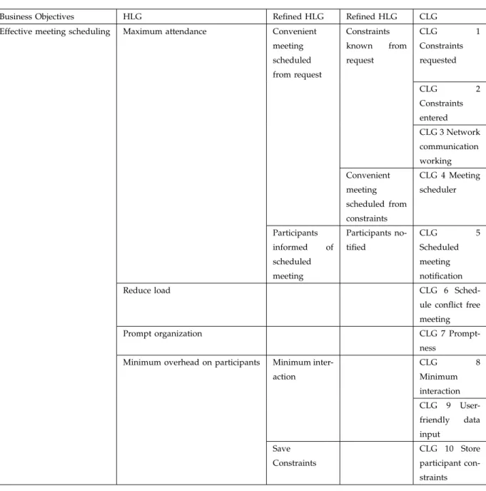
Business Objectives HLG Refined HLG Refined HLG CLG
Effective meeting scheduling Maximum attendance Convenient meeting scheduled from request Constraints known from request CLG 1 Constraints requested CLG 2 Constraints entered CLG 3 Network communication working Convenient meeting scheduled from constraints CLG 4 Meeting scheduler Participants informed of scheduled meeting Participants no-tified CLG 5 Scheduled meeting notification
Reduce load CLG 6
Sched-ule conflict free meeting
Prompt organization CLG 7
Prompt-ness Minimum overhead on participants Minimum
inter-action CLG 8 Minimum interaction CLG 9 User-friendly data input Save Constraints CLG 10 Store participant con-straints
meeting scheduled from request’ and ‘participants informed of scheduled meeting’. We then consider each refined goal and further elaborate it to the next hierarchical level of the goal model. For example, the refined goal ‘convenient meeting scheduled form request’ is realized by three functional concrete-level goals: ‘constraints requested’, ‘constraints entered’ and ‘network communication working’. Similarly, the refined goal ‘participants notified’ is realized by the concrete-level goal ‘scheduled meeting notification’. Furthermore, the high-level goal ‘prompt organization’ leads to a non-functional concrete-level goal, namely, ‘promptness’.
TABLE 3
MSS - Goal Dependency Analysis
Concrete Level Goals Usage Dependency Non-Functional Dependency Threats Dependency
CLG 1 Constraints requested CLG 2 CLG 4
CLG 2 Constraints entered CLG 1 CLG 8, CLG 9 CLG 10 CLG 3 Network communication
working
CLG 4 Meeting scheduler CLG 5, CLG 6, CLG 10 CLG 7 CLG 1 CLG 5 Scheduled meeting
notifica-tions
CLG 4 CLG 6 Schedule conflict free
meet-ings
CLG 4, CLG 10
CLG 7 Promptness CLG 6
CLG 8 Minimum interaction CLG 2
CLG 9 User-friendly data input CLG 2
CLG 10 Store participant constraints CLG 4, CLG 6 CLG 2
7.2 MSS Dependency Analysis and Goal Dependency Graph
We now investigate the dependencies between concrete-level goals, as shown in Table 3, and construct the goal dependency graph for MSS. We identify that CLG 1 ‘constraints request’ has a usage dependency with CLG 2 ‘constraints entered’ because its correct implementation requires support for constraints submission. CLG 2 ‘constraints entered’ has a non-functional dependency with both CLG 8 ‘minimum interaction’ and CLG 9 ‘user-friendly data input’ because these two non-functional concrete-level goals must be considered among the criteria for identifying components for CLG 2. CLG 3 ‘network commu-nication working’ has no usage, non-functional or threat dependency with other concrete-level goals of the MSS as it is a stand-alone functionality of the system.
Furthermore, CLG 4 ‘meeting scheduler’ has a usage dependency with CLG 5 ’scheduled meeting notification’, CLG 6 ‘schedule conflict free meeting’ and CLG 10 ‘store participant constraints’. The meeting scheduler needs to resolve meeting conflicts based on participant constraints to reduce load on meeting initiators and minimize overhead on participants. CLG 4 also has a non-functional dependency with CLG 7 ‘promptness’ because the MSS needs to promptly organize meetings to satisfy the overall business objective of effective meeting scheduling. CLG 6 ‘schedule conflict free meeting’ has a usage dependency with CLG 10 ‘store participant constraints’ because the conflict resolution process needs access to stored constraints data for its effective implementation.
As discussed in Section 7, there are two security concerns [14] to be taken into account for the MSS, namely, ‘meeting initiation should be restricted to authorized personnel only’ and ‘confidentiality rules should be enforced’. We identify that due to the first security concern, there is a threat dependency be-tween CLG 1 ‘constraints requested’ and CLG 4 ‘scheduler’. MSS requires a specific personal authorization
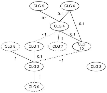
CLG 1 CLG 2 CLG 9 CLG 8 CLG 4 CLG 6 CLG 3 CLG 10 0.1 0.1 0.1 1 CLG 7 CLG 5 1 1 0.1 - 1 - 1 0.1
Fig. 4. Goal Dependency Graph for the Meeting Scheduling System
mechanism implemented between constraints request and scheduler to avoid the risk of unauthorized meeting initiation. Similarly, there is a threat dependency between CLG 2 ‘constraints entered’ and CLG 10 ‘store participant constraints’ due to the second security concern regarding the confidentially rules. Some security mechanism is needed between data input and data storage to prevent non-privileged participants from accessing other participants’ data. Figure 4 shows the goal dependency graph for MSS.
7.3 Cluster Formation in the Goal Dependency Graph
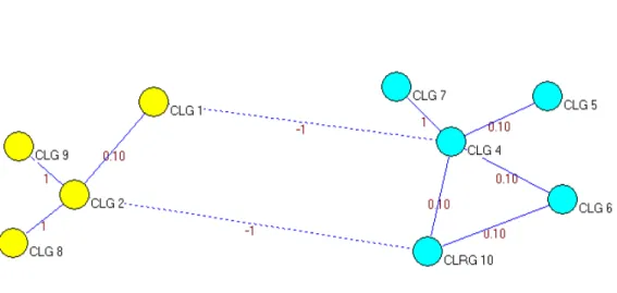
We use Pajek to cluster the goal dependency graph and Figure 5 shows a local optimal output. The cluster formation starts with ten clusters, that is, N OC = 10. The clustering error is calculated as 3.5. Subsequently, N OC is decreased to nine and the clustering error is calculated as 2.5. Table 4 shows the clusters and respective clustering errors for the MSS goal dependency graph, for different values of N OC. The clustering error decreases with decreasingN OC and becomes zero forN OC = 3,2 and again increases to 2 for one cluster. In this case study, we chooseN OC = 3(based on the heuristic discussed in Section 6.1) as it is the largest number of clusters that minimizes the error. Since the clustering error reduces to zero the local optimal clustering provided by Pajek is actually global optimal. Furthermore, in this example, the optimal clustering is unique with the cluster one consisting of CLG 1, CLG 2, CLG 8 and CLG 9; cluster two consisting of CLG 3; and cluster three consisting of CLG 4, CLG 5, CLG 6, CLG 7 and CLG 10.
Fig. 5. MSS Cluster Formation Using Pajek For NOC = 3
TABLE 4
MSS - Clusters in the Goal Dependency Graph
N OC Clusters Clustering Error
10 {CLG 1},{CLG 2},{CLG 3},{CLG 4},{CLG 5},{CLG 6},{CLG 7},{CLG 8},{CLG 9},{CLG 10} 3.5 9 {CLG 1},{CLG 2, CLG 8},{CLG 3},{CLG 4},{CLG 5},{CLG 6},{CLG 7},{CLG 9},{CLG 10} 2.5 8 {CLG 1},{CLG 2, CLG 8},{CLG 3},{CLG 4, CLG 7},{CLG 5},{CLG 6},{CLG 9}, {CLG 10} 1.5 7 {CLG 1},{CLG 2, CLG 8, CLG 9},{CLG 3},{CLG 4, CLG 7},{CLG 5},{CLG 6}, {CLG 10} 0.5 6 {CLG 1},{CLG 2, CLG 8, CLG 9},{CLG 3},{CLG 4, CLG 7},{CLG 5},{CLG 6, CLG 10} 0.4 5 {CLG 1},{CLG 2, CLG 8, CLG 9},{CLG 3},{CLG 4, CLG 6, CLG 7, CLG 10},{CLG 5} 0.2 4 {CLG 1, CLG 2, CLG 8, CLG 9},{CLG 3},{CLG 4, CLG 6, CLG 7, CLG 10},{CLG 5} 0.1 3 {CLG 1, CLG 2, CLG 8, CLG 9},{CLG 3},{CLG 4, CLG 5, CLG 6, CLG 7, CLG 10} 0 2 {CLG 1, CLG 2, CLG 3, CLG 8, CLG 9},{CLG 4, CLG 5, CLG 6, CLG 7, CLG 10} 0 1 {CLG 1, CLG 2, CLG 3, CLG 4, CLG 5, CLG 6, CLG 7, CLG 8, CLG 9, CLG 10} 2
TABLE 5
MSS - Candidate Components
CLG Candidate Components
CLG 1 - Constraints requested View, Panels, Content Template, CCK Block, Featured Content, Node Block, CCK Facets, View Scheduler, Calendar, Full Calendar
CLG 2 - Constraints Entered Input Stream, Input Format manager, Input Formats, Importer, Panels, Content Template, CCK Block, Node Block, User Import, Availability Calendar CLG 3 - Network Communication
Working
PingBack, MultiPing, Ping.fm, PingThis, Ping.FM Block, Ping Server, UserPing CLG 4 - Meeting Scheduler Make Meeting Scheduler, Scheduler, Node Scheduler
CLG 5 - Scheduled Meeting Notifi-cation
Notification, User Registration Notification, Team Notification, Notification Add-ons, Drupal Notifier, Notification Emails, Notification Tools, Make Meeting Scheduler, Scheduler
CLG 6 - Schedule Conflict Free Meeting
Make Meeting Scheduler, Scheduler, Node Scheduler
CLG 7 - Promptness N/A CLG 8 - Minimum interaction N/A CLG 9 - User-friendly data input N/A CLG 10 - Store Participant Con-straints
Make Meeting Scheduler, Scheduler, Node Scheduler, Signup Scheduler
7.4 MSS Component selection
In this section, we validate the practicality of the optimal clusters obtained in the previous section by analyzing their respective matching index values. Table 5 2 shows the potential list of candidate components for each MSS concrete-level goal, while Table 6 presents the matching index of the clusters formed at each stage of clustering. The matching index of a cluster consisting of a single non-functional CLG will be ‘undefined’ as a non-functional CLG requires an association with a functional CLG for component selection. In addition, when a non-functional CLG is clustered with a functional CLG, the matching index of the resulting cluster will usually decrease as we now select only those candidate components that satisfy both functional and non-functional CLGs. For example, when N OC = 10, the matching index of cluster 2, which consists of CLG 2 only, is 1. While forN OC = 9, the cluster 2, which now consists of CLG 2 and CLG 8, has matching index of 0.8. This is due to the exclusion of candidate components ‘Input Stream’ and ‘Availability Calendar’ as they do not satisfy the non-functional CLG 8, ‘minimum interaction’. For the present application, we specify the threshold valueT V = 0. This implies that there should be at least one candidate component available for each cluster.
For N OC = 3 (the optimal clustering), the matching index of each cluster is defined and non-zero.
2. No components can be associated with CLG 7, 8 and 9, as they are non-functional CLGs. These non-functional CLGs will act as selection criteria for related functional CLGs.
TABLE 6
MSS - Clusters and Matching Index
NOC Matching Index of Clusters
10 h1, 1, 1, 1, 1, 1, undefined, undefined, undefined, 1i
9 h1, 0.8, 1, 1, 1, 1, undefined, undefined, 1i 8 h1, 0.8, 1, 1, 1, 1, undefined, 1i 7 h1, 0.6, 1, 1, 1, 1, 1i 6 h1, 0.6, 1, 1, 1, 0.75i 5 h1, 0.6, 1, 0.75, 1i 4 h0.25, 1, 0.75, 1i 3 h0.25, 1, 0.18i 2 h0, 0.18i 1 h0i TABLE 7
MSS - Portfolio of Selected Components
NOC Clusters Identified Components Matching Index
3 C1{CLG 1, CLG 2, CLG 8, CLG 9} Panels, Content Template, CCK Block, Node Block
0.25 C2{CLG 3} PingBack, MultiPing, Ping.fm, PingThis,
Ping.FM Block, Ping Server, UserPing 1 C3{CLG 4, CLG 5, CLG 6, CLG 7, CLG
10}
Make Meeting Scheduler, Scheduler 0.18
Thus, the optimal clustering is practical and each optimal cluster represents a component of the MSS. It should be noted that the clusterings with respectively 10, 9 and 8 clusters are not feasible as the matching index for some clusters becomes ‘undefined’. This is due to the fact that some clusters represent a non-functional concrete-level goal and individual component selection is not applicable for them. Similarly, the clusterings with N OC = 1,2 are also not feasible as the matching index for at least one cluster becomes zero (i.e. equal to the threshold value).
For N OC = 7,6,5 and 4, the matching index values are defined and non-zero which means that component selection is feasible in this case. However,N OC= 3leads to a better solution for component selection as it minimizes the clustering error. Therefore N OC = 3represents the best trade-off between the availability of components and the interdependencies of system requirements. Table 7 shows the portfolio of candidate components that best match the MSS goals.
TABLE 8
MSS - Sensitivity Analysis of Weights
Instance Perturbed Weights Pajek Output Optimality
1 w(1,2) = 20,w(1,4) =−100,w(4,7) = 0.005 {CLG 1, CLG 2, CLG 8, CLG 9},{CLG 3}, {CLG 4, CLG 5, CLG 6, CLG 7, CLG 10} Global 2 w(1,2) = 200, w(2,8) = 100, w(2,9) = 50, w(4,5) = 10, w(4,6) = 200, w(4,7) = 100, w(4,10) = 500,w(6,10) = 25 {CLG 1, CLG 2, CLG 8, CLG 9},{CLG 3}, {CLG 4, CLG 5, CLG 6, CLG 7, CLG 10} Global 3 w(4,10) = 0.0001,w(1,4) =−0.0001,w(2,10) = −0.0001,w(2,8) = 0.0001 {CLG 1, CLG 2, CLG 8, CLG 9},{CLG 3}, {CLG 4, CLG 5, CLG 6, CLG 7, CLG 10} Global
7.5 Sensitivity Analysis of Dependency Weights
The aim of this section is to show that the clusters and the portfolio of candidate components obtained in the MSS case study are invariant of the choice of weights, as long as the threats are assigned arbitrary negative (not necessarily the same) weights while other dependencies receive arbitrary positive weights. To demonstrate this, let us denote a dependency (edge) between CLGi and CLGj as(i, j), wherei < j. Table 8 outlines the results obtained when some of the weight values are perturbed in the MSS goal dependency graph.
We observe that in all instances the best value of N OC, the Pajek output and hence the portfolio of candidate components remains unchanged. However, the clusterings and errors for other values ofN OC might change. For example, in instance 2 the clustering error for N OC= 4increases to 10 (the original value was 0.1). But this has no bearing on the final output.
8
CASE
STUDY
2 - CONSTRUCTION
MANAGEMENT
SYSTEM
Construction management software is extensively used in civil engineering domain. Construction projects require careful scheduling, comprehensive documentation and regular follow-up [52]. A number of commercial systems, such as Procore and Oracle Primavera, have been developed to manage the di-verse construction activities. Commercial construction management software typically offers a number of functionalities such as project creation, task management, scheduling, time-tracking, resource and personnel handling, report generation and managing invoices. In addition, support is provided to export the project data in a variety of formats such as PDF and MS Excel. Furthermore, it is often desirable to have a graph-theoretic representation of the project workflow in terms of nodes and edges. Also sometimes a genetic algorithm toolbox is provided to run simulations (for instance in Primavera). The system must incorporate security features as well to ensure the confidentiality of data.
In this section, we apply our component selection process to a component based Construction Man-agement System (CMS). The CMS is similar to the commercial systems described above in the sense that
TABLE 9
CMS - Goal Dependency Analysis
Concrete Level Goals Usage Dependency Non-Functional Dependency Threats Dependency
CLG 1 Task creation CLG 3, CLG 5 CLG 29 CLG 27
CLG 2 Enter task duration CLG 7 CLG 3 Task dependencies CLG 1, CLG 5 CLG 4 Task time tracking CLG 11, CLG 16 CLG 5 Project workflow
representa-tion
CLG 1, CLG 3
CLG 6 Project resources CLG 7, CLG 9 CLG 27
CLG 7 Project constraints CLG 2, CLG 6 CLG 27
CLG 8 Calender
CLG 9 Enter project team CLG 6 CLG 10 Graph theoretic project
rep-resentation CLG 20 CLG 11 Issues tracking CLG 4, CLG 16 CLG 12 Invoices CLG 13 Project comments/reviews CLG 14 Voting CLG 15 Project reports CLG 27 CLG 16 To-do-list CLG 4, CLG 11 CLG 17 Team discussions CLG 28
CLG 18 Export to Excel format CLG 19 Export to PDF format
CLG 20 Export to Graphviz format CLG 10 CLG 21 Email notification CLG 22 Data encryption CLG 23 CLG 23 User authentication CLG 22 CLG 24 Network communication CLG 25 System statistics CLG 26 Genetic algorithms CLG 27 Network storage CLG 1, CLG 6, CLG 7, CLG 15
CLG 28 Fast interaction between team members
CLG 17
CLG 29 User friendliness CLG 1
it offers similar functionalities.
8.1 CMS Concrete-Level Goals
The overall business objective of the CMS is to effectively manage construction project activities. This business objective can be refined into HLGs which can be further refined to reach CLGs of the system by using the methodology described in Section 4. Here we omit the details of goal elicitation as the process is essentially the same as the one in MSS case study. Instead we directly start by listing twenty nine
CLGs of the CMS in Table 9.
Within CMS, civil engineers can manage project by creating tasks (CLG 1), their durations (CLG 2), their precedence (CLG 3), track task progress (CLG 4) and any issues encountered (CLG 11). The CMS represents this information as a flow chart (CLG 5). Moreover, CMS records project resources, constraints and details of project team (CLGs 6, 7 and 9). Calendar is used to keep track of time (CLG 8). The CMS is also capable of representing project schedule as a graph consisting of nodes, representing project tasks, and edges, representing task precedence (CLG 10). The task durations are represented as node weights in the graph. This is an important feature as it offers greater visual insight. The CMS can export the graphical representation to Graphviz (CLG 20), which is a network visualization software. This enables engineers and project managers to analyze the graphical representation outside the CMS by using network analysis software like Graphviz or Pajek. The genetic algorithm support is provided (CLG 26) so the engineers and project managers can run simulations. Furthermore, the CMS generates project related documents like invoices (CLG 12), reports (CLG 15) and to-do-lists (CLG 16); exports them to commonly used file formats (CLGs 17 and 18); and supports communication between project team members (CLGs 13, 14, 17 and 21). Additionally, the CMS incorporates standard security (CLGs 22 and 23) and system related features (CLGs 24, 25 and 27). Finally, fast interaction between team members (CLG 28) and User friendliness (CLG 29) are two important non-functional goals of the system.
8.2 CMS Dependency Analysis
We have identified seventeen dependencies (four threats, two non-functional and eleven usage dependen-cies) between CMS concrete-level goals. For example, CLG 3 ‘task dependencies’ has a usage dependency with CLG 1 ‘task creation’ because its correct implementation requires tasks to be created in a project. Similarly, CLG 1 also has a usage dependency with CLG 5 ‘project workflow representation’. CLG 1 also has a non-functional dependency with CLG 29 ‘user friendliness’ because the CMS needs to have simple user interface to facilitate creation of a large number of tasks in a construction project. Similarly, CLG 20 ‘export to Graphviz format’ has a natural usage dependency with CLG 10 ‘graph-theoretic project representation’. Four threats arise in CMS due to a potential unauthorized access to task creation (CLG 1 - CLG 27), project resource details (CLG 6 - CLG 27), project constraints (CLG 7 - CLG 27) or activity reports (CLG 15 - CLG 27). Table 9 shows all these dependencies.
8.3 CMS Cluster Formation
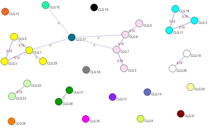
As in the MSS case study, we use Pajek to cluster the goal dependency graph of the CMS. The cluster formation starts with twenty nice clusters, that is, N OC = 29. The clustering error is calculated as 3.1. Subsequently,N OCis decreased to twenty eight and the clustering error is calculated as 2.1. The clustering error decreases with decreasing N OC and becomes zero from N OC = 18 up to N OC = 2; and again increases to 4 for one cluster. In this case study, we chooseN OC= 18(based on the heuristic discussed
TABLE 10
CMS - Clusters in the Goal Dependency Graph
N OC Clusters Clustering Error
29 {CLG 1},{CLG 2},{CLG 3},{CLG 4},{CLG 5},{CLG 6},{CLG 7},{CLG 8},{CLG 9},{CLG 10},{CLG 11},{CLG 12},{CLG 13},{CLG 14},{CLG 15},{CLG 16},{CLG 17},{CLG 18},{CLG 19},{CLG 20},{CLG 21},{CLG 22},{CLG 23},{CLG 24},{CLG 25},{CLG 26},{CLG 27},{CLG 28},{CLG 29} 3.1 28 {CLG 1 CLG 29},{CLG 2},{CLG 3},{CLG 4},{CLG 5},{CLG 6},{CLG 7},{CLG 8}, {CLG 9},{CLG 10},{CLG 11},{CLG 12},{CLG 13},{CLG 14},{CLG 15},{CLG 16}, {CLG 17},{CLG 18},{CLG 19},{CLG 20},{CLG 21},{CLG 22},{CLG 23},{CLG 24},{CLG 25},{CLG 26},{CLG 27},{CLG 28} 2.1 27 {CLG 1 CLG 29},{CLG 2},{CLG 3},{CLG 4},{CLG 5},{CLG 6},{CLG 7},{CLG 8},{CLG 9},{CLG 10},{CLG 11},{CLG 12},{CLG 13},{CLG 14},{CLG 15},{CLG 16},{CLG 17, CLG 28},{CLG 18},{CLG 19},{CLG 20},{CLG 21},{CLG 22},{CLG 23},{CLG 24},{CLG 25},{CLG 26},{CLG 27} 1.1 . . . . 19 {CLG 1, CLG 3, CLG 5, CLG 29},{CLG 2, CLG 6, CLG 7, CLG 9},{CLG 8},{CLG 10},{CLG 20},{CLG 4, CLG 11, CLG 16},{CLG 12},{CLG 13},{CLG 14},{CLG 15}, {CLG 17, CLG 28},{CLG 18},{CLG 19},{CLG 21},{CLG 22, CLG 23},{CLG 24}, {CLG 25},{CLG 26},{CLG 27} 0.1 18 {CLG 1, CLG 3, CLG 5, CLG 29},{CLG 2, CLG 6, CLG 7, CLG 9},{CLG 8},{CLG 10, CLG 20},{CLG 4, CLG 11, CLG 16},{CLG 12},{CLG 13},{CLG 14},{CLG 15}, {CLG 17, CLG 28},{CLG 18},{CLG 19},{CLG 21},{CLG 22, CLG 23},{CLG 24}, {CLG 25},{CLG 26},{CLG 27} 0 17 {CLG 1, CLG 3, CLG 5, CLG 29},{CLG 2, CLG 6, CLG 7, CLG 9},{CLG 8},{CLG 10, CLG 20},{CLG 4, CLG 11, CLG 16},{CLG 12},{CLG 13},{CLG 14},{CLG 15}, {CLG 17, CLG 28},{CLG 18},{CLG 19},{CLG 21},{CLG 22, CLG 23},{CLG 24}, {CLG 25},{CLG 26, CLG 27} 0 . . . . 3 {CLG 1, CLG 2, CLG 3, CLG 4, CLG 5, CLG 6, CLG 7, CLG 8, CLG 9, CLG 10, CLG 11, CLG 12, CLG 13, CLG 14, CLG 15, CLG 16, CLG 17, CLG 18, CLG 19, CLG 20, CLG 21, CLG 22, CLG 23, CLG 24, CLG 26, CLG 28, CLG 29}, ,{CLG 25},{CLG 27} 0 2 {CLG 1, CLG 2, CLG 3, CLG 4, CLG 5, CLG 6, CLG 7, CLG 8, CLG 9, CLG 10, CLG 11, CLG 12, CLG 13, CLG 14, CLG 15, CLG 16, CLG 17, CLG 18, CLG 19, CLG 20, CLG 21, CLG 22, CLG 23, CLG 24, CLG 25, CLG 26, CLG 28, CLG 29},{CLG 27} 0 1 {CLG 1, CLG 2, CLG 3, CLG 4, CLG 5, CLG 6, CLG 7, CLG 8, CLG 9, CLG 10, CLG 11, CLG 12, CLG 13, CLG 14, CLG 15, CLG 16, CLG 17, CLG 18, CLG 19, CLG 20, CLG 21, CLG 22, CLG 23, CLG 24, CLG 25, CLG 26, CLG 27, CLG 28, CLG 29} 4
TABLE 11
CMS - Candidate Components
CLG Candidate Components
CLG 1 Task Creation Strom, Project, Workflow, CCK Block
CLG 2 Enter Task Duration Input Stream, Input Format Manager, Input Formats, Content Template, CCK Block, Node Block
CLG 3 Task Dependencies Storm, Workflow
CLG 4 Task Time Tracking Time Tracker, Storm, Case Tracker CLG 5 Project Workflow
Represen-tation
Storm, Workflow
CLG 6 Project Resources Input Stream, Input Format Manager, Input Formats, Content Template, CCK Block, Node Block
CLG 7 Project Constraints Input Stream, Input Format Manager, Input Formats, Content Template, CCK Block, Node Block
CLG 8 Calender Calendar, Full Calendar, Availability Caldendar
CLG 9 Enter Project Team Input Stream, Input Format Manager, Input Formats, Content Template, CCK Block, Node Block
CLG 10 Graph Theoretic Project Representation
Graphviz tool box (Graphviz Filter, Graphviz Styles, Graphviz Noderef) CLG 11 Issues Tracking Storm, Project Issue Tracker, Case Tracker
CLG 12 Invoices Invoice, Ubercart PDF Invoice, e-commerce
CLG 13 Project Comments/Reviews Node Comments, Node Review, Customer Review, Review CLG 14 Voting Fivestar, Voting API, Advanced Poll, Rate, Node Vote
CLG 15 Project Reports Webform report, custom report, MySQL report, RDL report engine CLG 16 To-do-list Storm, To do list, Case Tracker,
CLG 17 Team Discussions Instant messenger, Chat room, Phpfreechat, DrupalChat, video Chat CLG 18 Export to Excel format View Excel Export, Ubercart CSV export, PhpExcel
CLG 19 Export to PDF format Webform2PDF, Fill PDF
CLG 20 Export to Graphviz format Graphviz tool box (Graphviz Filter, Graphviz Styles, Graphviz Noderef) CLG 21 Email Notification HTML Mail, Webmail Plus, Notification Email, Mime Mail
CLG 22 Data Encryption AES encryption, Login Security, Multisite Login
CLG 23 User Authentication LoginToBoggan, UserLoginBar, Login Security, Multisite Login CLG 24 Network Communication Rating
CLG 25 System Statistics PingBack, MultiPing, PingThis, Ping.FM Block, Ping Server, UserPing, Ping.Fm CLG 26 Genetic Algorithm D.A.I.L
CLG 27 Network Storage MySQL CLG 28 Fast Interaction Between
Team Member
N/A
![Fig. 1. The CBS Development Phases (Adapted from [19])](https://thumb-us.123doks.com/thumbv2/123dok_us/1397678.2687157/4.918.214.706.519.929/fig-cbs-development-phases-adapted.webp)