About the GSM-Dm-Channels
0. A little bit of History
In around 1986 a military Radio Transceiver was large (15 x 40 x 60cm) and heavy, weighing around 10kg. American devices were somewhat more sophisticated but only slightly smaller and lighter than the soviet equipment.
At the same time (1986) a “central co-ordination group”, called a nucleus, was set up to co-ordinate efforts for the development of a European Digital Mobile Radio System. What has happened in the world of communication?
Since Phillip Reis and Graham Bell invented the telephone engineers have had problems transmitting the signal over long distances. Noise always interferes with the useful signal. Amplifying the useful signal also means amplifying the noise. Until 1938 there was no way to prevent this....
Picture 1: Noise interference during communication
In 1938 the French engineer Reves had a revolutionary idea: “The signal can be sampled and the samples measured. Only the measured values, i.e. a stream of “0s” and “1s”, are then transmitted.” i.e. the analog voice signal is changed into a digital signal
the order of centimeters. An experimental breadboard circuit comprising of a twenty four-channel PCM device built in 1949 in East Berlin was as large as a sitting room.
For this reason an ISDN at that time was out of the question. A lot of thought and time were necessary to bridge the gap.
You might ask ‘Why are we considering the development of ISDN?’
The reason, as you shall see, is that the development of ISDN was prerequisite to the development of GSM, not only from a technological point of view, but also because of the amount of thought required to work out the signaling between a telephone station and a network. As you can read in the ‘How To’ section of this CBT, GSM Pioneers Michel MOULY and Marie-Bernadette PAUTET call ISDN ‘the Godfather of GSM’ because the work was inspired by the principles of ISDN and its access protocols.
Now let’s move onto a short history of the technological development of electronics and have a look at the following picture:
1938 Invention of PCM by Reves
1943 The World’s first digital Computer is built by Konrad Zuse 1948 Bardeen and Brattain invent the Transistor
1959 Noyce builds ICs in a planar process 1965 PCM in local telephone networks 1971 Ted Hoff invents the microprocessor
1972 In a Japanese publication the concept ISDN appears for the first time
1975 Local exchanges are controlled by microprocessors 1980-85 CCITT (today ITU) passes the main ISDN Standards 1982 Decision of DBP to introduce ISDN
1989 ISDN is introduced in Germany 1989 MoU introduces Euro-ISDN (DSS-1) 1993 Euro-ISDN is introduced in Germany
Picture 3: Timetable of main inventions leading to ISDN and therefore GSM
This is the background of events leading to the development of GSM: 1958 A-Network, first German Mobile Cellular Network starts
1979 The first Cellular System AMPS (Advanced Mobile Phone Service) is invented in Chicago, USA (analog)
1981 Sweden begins the Nordic Mobile Telephone System (analog)
1982 "Groupe Spècial Mobile" is created within CEPT (Conférence Europé- enne des Postes et Télécommunications)
1985 C-Network (analog) is invented in Germany
1986 A Permanent Nucleus (a central co-ordinating group) is set up 1987 Memorandum of Understanding (MoU) GSM between 12 countries
1991 First Systems are running (Telecom 91... Exhibition) (GSM now stands for Global System for Mobile Communication )
2000 357 GSM-Networks with 311 million subscribers in 133 countries
Picture 4: A Short History of GSM development
As you can see in picture 4, until the 1990s analog radio equipment was used in civil as well as military radio equipment.
However, during the introduction of analog devices into daily service, scientists in Europe worked to develop a very new technology made possible by the digital revolution.
We will now consider:
- what is the Global System of Mobile Communication? - what are its components and how does it work?
- what are the basics of communication between the Mobile station and Network?
1. Structure and Components of a Mobile Network
Please consider the picture of components and interfaces in a Public Land Mobile Network.
Picture 5:Components and Interfaces in a Public Land Mobile Network PLMN
1.1 The Mobile Station
I shall begin with a description of the element on the far left, the Mobile Station.
You must bear in mind that a mobile station represents the latest developments not only in miniaturized electronics but also in:
- compression of speech to minimize bandwidth
- encoding to avoid eavesdropping of speech or data messages
- coding and decoding to detect and correct failures during transmission over the air interface.
There is an interesting difference between the Mobile Equipment and the Mobile Station. The former is the body, you only have the latter once you have added the Subscriber Identity
1.1.1 The Mobile Equipment
The ME is asmall transmitter–receiver station equipped with large-scale integrated circuits which allow:
- High-level digital filtering to enable a very short changeover time - Fast signal processing and highly stable oscillators
- High performance signal processing for encoding and decoding of information
- Battery power supply allowing long standby time and a transmitting power of up to 8 watts - Colour display with high resolution suited to viewing pictures taken by a 1.3 MB Pixel camera
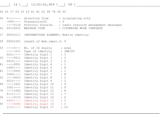
- The body is characterized by an International Mobile Equipment Identity (IMEI). The IMEI consists of 15 digits (60 bits). There is a 6 digit type approval code TAC, a 2 digit Final Assembly Code FAC, 6 digit serial number SNR and a 4 bit space SP.
1.1.2 Subscriber Identity Module
The SIM consists of the mobile’s data bank and free usable memory. The data bank consists of:
Administrating data
- The Personal Identification Number PIN - The Pin Unblocking Key PUK
- The SIM-Service Table Authentication and Ciphering
- The Encoding algorithms (A3, A8), identical to the ones held in the network, and the authentication computation
- Ciphering Key Sequence Number (CKSN) (3 bit) identical to the one held in the network - The highly secret Kc and Ki
Subscriber specific
- International Mobile Subscriber Identity IMSI, consisting of 15 digits or less with a 3 digit mobile country code MCC, a 2 digit mobile network code MNC and an up to 10 digit mobile subscriber identification number MSIN - Temporary Mobile Subscriber Identity TMSI, given to the mobile by the network during roaming (to hide the IMSI)
Roaming data
- Local Area Identity LAI - Preferred PLMNs list
- Forbidden PLMNs list
- List of beacon frequencies (ARFCNs of the home PLMN) - Storage of location information
Personal data of the user
- Directory number of a mobile radio subscriber MSISDN - Storage of SMS, Telephone Numbers etc.
The most attractive feature of the separation of ME and SIM is that it makes it possible to put the SIM into another ME. In this way I have upgraded my mobile communication from GSM to GPRS to UMTS, in each case using newer Mobile Equipment but the same SIM-Card.
1.2.The Base Station Subsystem BSS
The Base Station Subsystem is coloured green in picture 5. Its main components are:
1.2.1 The Base Transceiver Station (BTS)
The Base Transceiver Station realises the Air-Interface between mobile and network. It consists of:
- the antennas
- output and input filters, which are band-pass filters. While the input filter is broadband and not tuneable, the output filter is wideband and tuneable
- radio transmitter and radio receiver
- the Transmission/Reception-Module TRX which serves: Channel Coding and Decoding, Ciphering, Slow Frequency Hopping, Burst formatting, Gausian Minimum Shift Keying (GMSK) of all transmitted and received data, the generation and sending of the BCCH on Channel 0, the realisation of the protocol LAPD on the channel to the BSC
- Operation and Maintenance (O&M) Module.
1.2.2 The Base Station Controller (BSC)
The Base Station Controller is the BSS’s centre of intelligence. It consists of : - a switching array which connects several BTSs to the MSC
- a data bank in which the quality and availability of the radio resources are stored and the status of the BSS-Hardware is dynamically watched
- a central processing unit (CPU) which makes the handover decisions.
1.2.3 The Transcoding Rate and Adaptation Unit (TRAU)
The Transcoding Rate and Adaptation Unit is responsible for compressed data transmission on the air interface. The compression method used is called Regular Pulse Excitation-Long Term Prediction (RPE-LPT).The bit rate of an ISDN channel with 64 kbit/sec is reduced to a bit rate on the air interface of 16 kbit/sec (if the Full Rate Transport Channel is used).
1.3. The Network Switching Subsystem (NSS)
The Network Switching Subsystem is dark yellow in picture 5. It is the central part of any Mobile Radio System and controls several BSSs. Its components are responsible for all the call processing, controlling and data bank functions which are necessary to examine the authentication, to make set-up the call, to encrypt the data and to control roaming. Its components are:
1.3.1 Mobile Services Switching Centre MSC
The MSC is a standard ISDN-switching system adapted to be used in Mobile Radio
Networks. It takes over the exchange of channels inside a PLMN or between several PLMNs and controls handover between several MSC areas.
The MSC also adapts protocols between Call Control (ISDN-typical) and ISDN User Part ISUP as used in SS#7
The MSC receives the information necessary for switching a signal processing from the HLR and the VLR (see paragraphs 1.3.3 and 1.3.4).
trunk network using the SS#7 and arrives at the GMSC. The GMSC initiates a search for the called subscriber using their Home Location Register. It then switches to the responsible MSC which links the call to the BSC and a BTC where the subscriber is camping. The call is then sent with a PAGING REQUEST to the wanted subscriber.
1.3.3 Home Location Register HLR
Generally one PLMN consists of several HLRs. The first two digits of the mobile directory number (e.g. 0171 2620757) are the number of the HLR where the mobile subscriber is stored. Among other things, the following data from any subscriber is stored: Subscriber specific:
- IMSI - Ki
- Restriction of services - Supplementary Services - Directory Number (MS ISDN) Authentication and Ciphering: - Algorithm A3
- Algorithm A8 - RAND, SRES, KC
Seeking for Subscriber/Call Control
- Information related to the current location of the subscriber e.g. the actual VLR - Number of the MSC
1.3.4 Visitor Location Register VLR
A VLR stores subscription data for those subscribers currently situated in the service area of the corresponding MSC. A subscriber who logs into an allowed PLMN is registered by the responsible VLR after the latter has asked for their user data from the responsible HLR. A VLR function is integrated with every MSC. The following information is stored in the VLR Subscriber specific:
- International Mobile Subscriber Identity IMSI - Temporary Mobile Subscriber Identity TMSI
1.3.5 Equipment Identity Register EIR
Every MS possesses an International Mobile Equipment Identity IMEI. It is possible to ask for this ID by typing the string *#06# on the Mobile. The IMEI is stored in the EIR in a so-called ‘white-list’. A ‘black-list’ contains a list of defective or stolen MS and this equipment is therefore blocked.
2. About Interfaces
Please have another look at picture 5 where you can see 3 main interfaces: the Air interface Um, the Abis interface and the A (BCF) interface. In this lecture we will deal mostly with the Air interface (Um) because we have equipment to trace the signal channels of this interface i.e. we are able to prove all statements with an experiment.
In lectures about ISDN we will deal mainly with the D-Channel, the signal channel of the final mile. However, in order to have an overview of the sophisticated system of signalling between a mobile and an ISDN telephone, in the following paragraph we will provide a description of the main features of signalling in a network.
2.1. The Abis Interface.
The Abis interface between BTS and BSC is typical ISDN. It is built by a PCM 30-interface, i.e. there are 30 channels with a speed of 64 kbit/sec. A full rate GSM data channel is
compressed to16 kbit/sec. Thus 4 GSM channels fit into a 64 kbit/sec ISDN-channel. Layer 1 and Layer 2 are the same as in ISDN-channels.
Picture 6: Layer 3 in the Abis interface
In Layer 2 there exists a SAPI and a TEI (see § 5.1). The number of the TEI corresponds to the number of the BTS to which the message is sent. As you can see in Picture 6, the Protocol discriminator in ISDN is exchanged to a Message discriminator and a flag which decides whether or not the message is to be treat transparently into the BTS. The following three octets are instructions for controlling the the BTS and telling this component how to process the contents of the data field. For more information see [2].
2.2 The A-Interface
The A-Interface is built by several PCM-primary groups (a primary group consists of 30 PCM channels). In a Primary group, channel 16 is the signal channel (this is known from ISDN and SS#7). The data rate of the message channels between TRAU and MSC is 64 kbit/sec. This is a sampling rate of 8000 where each sample consists of 8 bits. Between the Transcoder/Rate Adaptor Unit TRAU and BSC the message channels are compressed to 13 kbit/sec,
i.e. speech is transmitted using groups of 260 bits every 20m.
Signalling is made by the Signalling system Number 7 (SS#7) especially by the Signalling Connection Control Part (SCCP),
the Base Station Subsystem Application Part (BSSAP) and
3. Information about the Signalisation System Number 7 (SS#7)
In the digital trunk network the signalling channels do not run in the same cable as the information channels. The signalling network is therefore a separate network beneath the network of information cables.
Picture 7: The digital trunk network
The information in this network runs between Signalling Points which route the signal streams. The signalling networks of different countries are connected worldwide as you can see in picture 8. This picture is tailored to the communication between operators of the different mobile networks, T-mobile, Vodafone, O2 and so on.
.
Picture 8: Structure of the German signalling network
The next picture shows how a message in SS#7 is structured. The signalling system in the trunk network is older than the signalling system in the ISDN. Therefore the construction of the layer 3 frame shown in picture 9 differs from the frames we know from the ISDN. The part of the signalling system SS#7 which allows the transfer and maintenance of signalling messages in the national and international Trunk Network is called the Message Transfer Part MTP. The MTP may be divided into three layers known from the OSI model. MTP1 is known as the Signalling Data Link (Bit Layer).
MTP2 defines the principle frame structure known from the Link Access Protocol used in the ISDN D-Channel (LAPD).
We will deal only with MTP3 which describes the signalling message handling dependent on the served user (e.g. ISDN =>ISDN Served User Part ISUP).
The control information is, for example, put into a frame called the Message Signal Unit MSU.
As you can see from the different service information octets the content of the Message Signal Unit MSU may serve several different uses.
.
Picture 9: The Message Signal Unit MSU
Let’s have a look at the case where the MSU transports the Signalling Connection Control Part SCCP.
The SCCP is, like the ISDN User Part ISUP, an application of MTP. It grants network functions to other subsystems.
A subsystem using this network function is the Transaction Capabilities ApplicationPart. The TCAP, for example, can convey user data from a HLR to a VLR in the international trunk network.
Picture 10: The Signalling Connection Control Part SCCP
From all this complicated information you need only keep in mind that there is data which is put into frames which are then stacked into each other for transportation in the worldwide signalling network☺
4. Layer 1 on the air interface
4.1 Frequencies used in Mobile Communication
4.1.1 GSM 900
In GSM 900 there are two frequency bands, one for Uplink (890.2-915 MHz) and the other for Downlink (935.2-960 MHz).
Both are at a distance of 20 MHz from each other.
Frequencies are expressed by channel numbers 1 to 124 (the so-called ‘ARFCN’ = Absolute Radio Frequency Number).
Channel numbers are used in messages instead of explicit frequencies. If the ARFCN = n is known the absolute frequency can be calculated by
for the downlink: F(DL) = (935.2 + 0.2*(n-1) MHz, for the uplink: F(UL) = (890.2 + 0.2*(n-1) MHz,
Picture 11: Frequency plan GSM 900 4.1.2 Extended GSM
In order to create more frequencies after starting GSM an Extended Bandwas defined.
Uplink (880.4-890.0 MHz)
Downlink (925.4- 935.0 MHz)
In Extended GSM the channel numbers are n= ARFCN=975-1023. The absolute frequency can be calculated by
4.1.3Digital Communication System 1800
In the Digital Communication System 1800there are the frequencies Uplink (1710-1785 MHz) and
Downlink (1805-1880 MHz).
If n = ARFCN=512-885 the absolute frequency can be calculated by for the downlink: F(DL) = (1805.2 + 0.2*(n-512) MHz, for the uplink: F(UL) = (1710.2 + 0.2*(n-512) MHz,
4.1.4 An Exercise with OT Drive PC and Mobile OT 260
Let's have a look at which frequencies with which field strengths can be measured at the author’s residence.
Picture 12: Scanning frequencies with OTDrivePC and OT260
You must bear in mind that a field strength of less than around -102 dB is unusable for a GSM-connection. Therefore the GSM-Channels 3,4,5,6,7, 16, 19, 21, 30 in picture 12 can be used to set up a call. We don't yet know to which operator the selected channels belong but we will deal with this problem later.
4.2 The Cellular coverage representation
Because of the restricted reach of the mobile transmitter on these frequencies it is possible to reuse all frequencies in a calculable distance.
.
Picture 13: A cellular array
4.3 The frequency time division principle
As mentioned in paragraph 4.1.4 the Operators (D1, D2, O2 etc) have to share the amount of existing frequencies. Thus the number of usable frequencies in one cell per operator is reduced still more. By using time-division the number of possible subscribers increases again.
Picture 14: Time Division Multiple Access TDMA
As you can see in picture 14, at every GSM frequency bursts of 576.9 /u sec are emitted. Eight consecutive bursts emitted are called a frame. The bursts in a frame are numbered from 0 to 7. If a mobile requests a channel it receives a dedicated frequency and a timeslot.
As you can also see in picture 14, the data stream between a mobile and the BTS consists of a stream of bursts. We shall deal with the construction of a burst later in this lecture.
Now we have to consider how the consecutive frames are numbered.
The Time Division Multiple Access frames are not simply repeated but are put into a hierarchy of frames. The frame number is not repeated until 3h, 28min, 53s, 750m (see picture 15).
The reason for this peculiar mode of counting is the use of the frame number during the encoding procedure.
Picture 15: Frame hierarchy (See Mouly, Pautet, “GSM ...”)
Let's have a look at picture 15. To build a transport channel the frame in the lower left corner is first put into a multi-frame consisting of 26 TDMA frames.
To build a control channel the frame in the lower right corner is first put into a multi-frame consisting of 51 TDMA frames. The reason for this will be explained later.
4.4 About GSM channels
We are now able to make some statements about GSM channels.
The GSM channel consists of the arrangement of bursts in a row, possibly situated on different frequencies.
You must distinguish between fixed frequency channels, where the time slots always belong to the same frequency, and frequency-hopping channels, where the time slots may belong to different frequencies
Traffic channels are bi-directional. Their frequency separation (uplink and downlink) amounts to 45 MHz in the 900 MHz band and 75 MHz in the 1.8 GHz Band.
In addition there is a time shift of 3 Burst Periods (BP) between transmitting and receiving which allows the same Timeslot Number to be used for up and downward transmission. Traffic channels are built by grouping 26 TDMA frames into a multi-frame. Out of the 26 timeslots 24 BP are used to build TCH/F, one to build a Slow Associated Control Channel and one slot is kept free.
A Slow Associated Control Channel (SACCH) is always compounded with a full rate Traffic channel TCH/F.
The frame of a control message consists of 23 octets. 4 Bursts are necessary to transmit it over the air interface. In one multi-frame there is only one burst to build the SACCH. Hence it lasts 4 times 120m, i.e. 0.48 sec to generate a SACCH-frame.
The time of 120m for one multi-frame stems from the need of easy synchronisation with the ISDN. This is the reason for the duration of one Burst Period.
120/(26x8)m = 15/26m ~ 0.577m
As already mentioned, the burst reserved for SACCH in the TACH/F frame allows a control message to be sent every 480m.
In contrast to this, the empty burst is necessary to make measurements on neighbouring channels. As you can see in Picture 16 the time gained is 12x15/26 = 6.92m.
.
4.5 About Bursts
Please have a look at picture 17. In GSM there are five different Bursts.
Picture 17: The construction of bursts
The Normal Burst consists of two packages each of 58 bits grouped around the so-called ‘Training Sequence’. The 58 bit packages consist of 57 bits of error-protected user data. One bit is called the Stealing-Flag. If the S-Flag is set, the Burst is stolen to build a Fast
Associated Control Channel FACCH.
The Training Sequence is a sequence of Bits with a pattern known to the transmitter and receiver. It is used to adjust the parameters of the equalizer circuit and to guess the bit error rate. There are 8 different Training Sequences. Normal bursts are used to build the Transport Channel.
The Frequency Correction Burst consists of 142 zero bits. During the process of finding a beacon signal (this process will be discussed later) the mobile can adjust its frequency to that of the strongest signal found.
Following this the mobile can read the Synchronisation Burst. The Synchronisation Sequence allows the mobile to adjust to the bit stream and to read beneath other information to discover which operator the signal belongs to.
The Access Burst is used if the mobile has to ask the network for a channel. This process will also be discussed later.
The Dummy Burst looks similar to a Normal Burst. Bursts are to be sent continuously by the mobile and by the network. Sometimes it might occur that a burst is to be sent but no useful burst is available, in this case the dummy burst is taken.
4.6 Idle mode and dedicated mode
If an active connection exists between the Mobile (MS) and Base-station (BS) the MS is said to be in dedicated mode.
If the mobile is switched on but remains passive to the network the mobile is said to be in idle mode.
In idle mode the MS has to listen to the Paging Channel in order to detect a call to its address and to read the System Information sent by the Broadcast Control Channel (BCCH)
Picture 18: Control Channels in GSM
Please try to find these channels in Picture 18. The following channels are used in idle mode: Frequency Correction CHannel in search of a new beacon frequency
Synchronisation CHannel in search of a new beacon frequency Broadcast Control CHannel while monitoring the System Information
Paging CHannel while monitoring whether there is a call
Access Grant Channel waiting for the Immediate Assignment of a channel Random Access Channel sending a channel request to the network
Access to these channels is possible following the burst sequence shown in picture 19.
Picture 19: A burst sequence at the beacon frequency time slot 0
The illustrated sequence of Bursts is always sent on slot 0 of the beacon frequency. You can see that a SCH Burst follows a FCCH burst exactly 8 Bursts later. The following 4 Bursts set up a message from the Broadcast Control Channel (BCCH). The next 4 Bursts set up a message from the Paging Channel, and so on. As will be explained later, one message frame
Now have another look at picture 15. The absence of a common divisor in the cycles 26 and 51 in the left and right lower corners serves the following purpose:
a Mobile station being in dedicated Mode, i.e. sending and receiving Bursts in a “26 multi-frame”, is periodically able to measure the Synchronisation Channel and the Frequency Correction Channel in the “51 multi-frame” of the neighbouring BS (Pre-synchronisation). If there was a common divisor in the two multi-frames it might happen that, during the gap shown in picture 19, the same bursts but not the SCH or FCCH are seen. If there is no common divisor another burst in the sequence (as shown in picture 19) is always seen.
4.7 How the Mobile finds the BCCH
As mentioned above, there is a beacon frequency(BCCH), a distinguishing frequency in a cell. In timeslot 0 all the modulated channels shown in Picture 19 are downlinked. The Bursts associated with these channels are shown in Picture 17. After being switched on the mobile seeks the strongest transmitter, in most cases this is a BCCH. As is explained above, in timeslot 0 of this frequency a Frequency correction Burst is emitted and eight BP later a Synchronization Burst. The MS will therefore first seek the strongest transmitter and then the Frequency Correction Channel with which it can adjust to the BTS.
From the Synchronisation Burst (8 BP after the Frequency correction Burst) the Mobile learns the exact number of the timeslot in the cycle of the 8 x 26 x 51 x 2048 Burst Periods.
The MS furthermore learns the Base Station Identity Code (BSIC).
The Base Station Identity Code BSIC consists of 6 bits combined from NCC and BCC (each with a length of 3 bits). Allowed and disallowed NCC’s are stored on the SIM card.
Therefore a mobile equipped with a SIM-Card issued by operator D1 cannot camp on a BTS of operator D2 even if this BTS is emitting a stronger carrier.
Let’s have a little exercise to find out which frequencies have which signal strength and belong to which Operator (NCC) having which BCC.
Picture 20: A look at OTDrivePC during BCCH scanning and BSIC detecting
If we start OTDrivePC and click File->Connect and Scanning->BCH-Scanning->BSIC-detection we will seea picture similar to the detail shown in picture 20. The mobile scans the whole (e.g. the 900 MHz) band. Beneath the line of ARFCNs you can see a line which shows whether or not the frequency is a beacon frequency. A beacon frequency is represented by two digits connected by a hyphen (NCC-BCC). The NCC of T-Mobile (D1) is “3”. Vodafone (D2), being an international player, possesses NCCs 4, 5, 6 and 7. System Information Type 2 tells the mobile which NCCs are allowed.
Two transmitters not far from on another could be emitting the same BCCH frequency. It must be possible to distinguish between these carriers when they are both received by one mobile. Therefore, during the planning and building a network, neighbouring BCCH with the same frequency are assigned a different “colour”. This colour is represented by the terminus Base Station Colour Code (BCC).
4.8. About the idle mode
After the mobile has found an allowed BCCH it registers with the network. This process is called LOCATION UPDATE and we will discuss it in greater detail later. After this the mobile watches the PAGING REQUEST messages waiting for a call. This mode is called the ‘idle mode’. Let’s have a look at the messages the Mobile receives in idle mode.
To do so, start OTDrivePC, click File->Connect, Trace-> Define... -> Select all -> Send... In the window Layer Messages we can find PAGING REQUEST TYPE 1 (2). Some of this will be passed to layer 3. On the other hand all of the SYSTEM INFORMATION TYPE 1, 2, 3, 4, 13, are passed to layer 3.
Picture 21:The “Layer Messages” window of the OTDrivePC tool.
When it was last connected to the network the mobile received a Temporary Mobile
Subscriber Identity (TMSI), a number 4 octets in length assigned by the network. The mobile receives a new TMSI from the VLR when every new connection is made. The TMSI was introduced to make the tracking of a subscriber more complicated.
4.9 The Mobile is called
If the mobile is called it recognizes its address (TMSI) in a message from the Paging Channel. The mobile has to request a channel in response and uses the Random Access Channel to do
distance to the BTS and consequently does not know the delay with which the burst will arrive at the BTS.
The construction of the Access Burst allows it to fit into the receiving window of the BTS even if the Burst arrives with time delay. The BTS is now able to calculate the so-called ‘Timing Advance’ TA and inform the mobile about it.
4.9.1 Timing Advance
After the Access Burst has been decoded the signal delay is computed by the BTS and transmitted to the mobile by signalling.
The value of the Timing Advance TA can be between 0 and 232/us, expressed by 0 to 63 bits (that is 1 bit = 48/13/us). If the TA is known the distance between the mobile and BTS can be calculated.
TA = 0 means the mobile is not more than 300m away from the BTS. The distance increases by 550m per Bit of the TA. i.e.
Distance/m = 300m + (TA/bit x 550)m.
A mobile at a distance of more than 35 km from the BTS is unreachable.
4.9.2 Content of the ACCESS BURST
At the beginning of the ACCESS BURST there are 8 Tail bits in fixed code with the pattern "00111010" followed by a Synchronization Sequence of 41 bits. This pattern allows the BTS to distinguish the ACCESS BURST from random noise.
The following 36 data bits contain only 8 information bits (yyyxxxxx). At least 3 bits (y) contain the cause of the channel request(for instance "Emergency call", "Answer to paging ...", "Originating call ..."). The other bits (x) form a random digit which allows this ACCESS BURST to be distinguished from another one arriving at the BTS at the same time.
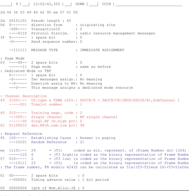
4.10 The message IMMEDIATE ASSIGNMENT
In response to the Channel Request the BTS sends the message IMMEDIATE
ASSIGNMENT on the ACCESS GRANT CHANNEL (AGCH). The AGCH takes the timeslot normally used by the PCH (and is therefore named PACH).
The message IMMEDIATE ASSIGNMENT dedicates a working channel to the MS (a so-called ‘Slow Dedicated Control Channel’) and tells the mobile where to find this channel, i.e. - the type of the logical channel,
- the frequency, - the time slot,
- the frame number expressed by the three Parameters T1, T2, T3, - the Timing Advance Value,
and so on.
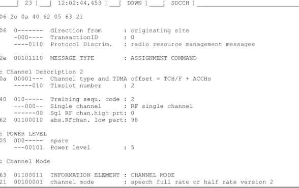
The message IMMEDIATE ASSIGNMENT enables the MS to exchange information with the BTS. A translated frame of this message is over the page:
_____[ 9 ]___[ 12:02:42,320 ]___[ DOWN ]____[ CCCH ]______________________________ 2d 06 3f 03 49 40 62 95 ee 57 01 00
2d 00101101 Pseudo length : 45
06 0--- direction from : originating site -000---- TransactionID : 0
----0110 Protocol Discrim. : radio resource management messages 3f 0--- 1 spare bit : 0
-0--- Send sequence number: 0
--111111 MESSAGE TYPE : IMMEDIATE ASSIGNMENT : Page Mode
03 ----00-- 2 spare bits : 0
---11 Page mode : same as before : Dedicated Mode or TBF
0--- 1 spare bit : 0
-0--- Two messages assign.: No meaning --0--- Downlink assig to MS: No meaning
---0---- This message assigns a dedicated mode resource : Channel Description
49 01001--- Ch.type & TDMA offs.: SDCCH/8 + SACCH/C8|CBCH(SDCCH/8),SubChannel 1 ---001 Timslot number : 1
40 010--- Training sequ. code : 2
---000-- Single channel : RF single channel ---00 Singl.RF ch.high prt: 0
62 01100010 abs.RFch.num.low prt: 98
: Request Reference
95 100--- Establishing Cause : Answer to paging ---10101 Random Reference : 21
ee 11101--- 29 = (T1) coded as bin. represent. of (Frame Number div 1326) mod 32.
---110 6 = (T3 high)is coded as the binary representation of Frame Number mod 51. 57 010--- 2 = (T3 low) is coded as the binary representation of Frame Number mod 51.
---10111 23 = (T2) is coded as the binary representation of Frame Number mod 26. : The frame number, FN modulo 42432 can be calculated as 51x((T3-T2)mod 26)+T3+51x26xT1'
01 00--- 2 spare bits : 0
--000001 Timing advance value : 1 bit period 00 00000000 lgth of Mob.Alloc.IE : 0
Table 1: Immediate Assignment
We can see how this looks on the radio channel (the air interface) by starting the Exercise CD item ‘Raw traces’. Please click "call from the ISDN to the D1 Mobile Network”. As opposed to a live-trace the Excel sheet gives an overview of the whole transmission.
In Picture 22 you can see detail from the EXCEL sheet made from a trace captured by OTDrivePC. Let's have a closer look at this picture:
- On line 19 appears a (Layer 3) PAGING REQUEST message which consists of the TMSI of our Trace Mobile.
- The mobile immediately sends the CHANNEL REQUEST MESSAGE (there is no time difference detected)
- 664m later the network answers by sending the IMMEDIATE ASSIGNMENT MESSAGE (Line 52) which is copied to Layer 3 (Line 53)
- Only 47m later the mobile answers with a PAGING RESPONSE Message - This Message is sent on Layer 2 together with a SABME
In response to the IMMEDIATE ASSIGNMENT Message, the message PAGING
Picture 22: Excel representation of a MTC (detail)
4.11 Dedicated Channels
As shown in the paragraph above, the network dedicates a channel to the mobile. Now we have to deal with the questions: What are dedicated channels and how are they organized? The dedication of a Transport Channel is quite simple. The mobile receives a frequency, a timeslot and a frame number. However, if we only have to negotiate between the network and mobile conditions for the connection to be established, dedicating a full transport channel to this task is a waste of channel capacity.
The authors Mouly and Pautet say only an eighth of the valuable capacity of a Transport Channel (TCH/F) is necessary to transport this control information. They call this Signal channel TACH/8 (TACH stands for the combination TCH/SACH)
In GSM-Specifications this eighth TCH is called the SDCCH (Slow Dedicated Control CHannel). The SDCCHs are organized in a cycle of 102 consecutive bursts (as shown in picture 24). One possible configuration of the cycle consists of the following:
8 consecutive series of 4 bits, each belonging to one SDCCH (called Sub channel 1-8). Then 4 consecutive series of 4 bits, each belonging to one SACCH. Three slots are left unused.
Picture 23: Organisation of a TACH/8
In the illustrated time organization, eight SDCCH/SACH/8 sub-channels exist. A grouping of only four sub-channels is also possible.
4.12 How to transport a layer 2 frame to layer 1
A layer 2 frame may convey a maximum of 23 octets of control information (i.e. a length of 184 bits). These 184 bits are encrypted by a Fire Code represented by the polynomial (x23+1)(x17+x3+1)
This Fire Code allows the correction of burst errors up to the weight of eleven.
By encryption the length of the frame is enlarged to 184 + 40 = 224 bits (4 bits are added, so the length of the frame is 228).
It is expected that the mobile channel will contain a high density of burst errors. This means the error correction capability of 11 consecutive wrong bits is not sufficient. There is a trick to overcome this:
We spread the sequence of 228 bits to 456 bits by a so-called ‘convolutional code’. Imagine that the convolutional code inserts one dummy bit between two of the 228 information bits.
If there are large bursts of error bits half of them meet dummy bits. This increases the probability of the Fire Code correcting the 11 errors in the 228 bit sequence.
The final coding action is to put the 456 coded bits into 4 Normal Bursts (each consisting of 114 information bits), see picture 24.
Picture 24: Copying a Layer 2 frame onto Layer 1
5. Construction of Layer 2 and Layer 3 in GSM
The information about the length of a layer 2 frame given in the last paragraph is illustrated in picture 25.
Picture 25: The construction of frames on the air interface
You must distinguish between layer 2 frames in protected mode and layer 2 frames in unprotected mode.
While the first construction is known from the ISDN, the latter is new. Please see picture 26 for the coding of the eight bits of the Pseudolength.
Picture 26: Pseudolength and types of Information Elements.
A message is dividet into IE. In some messages it is necessary to transfer information in a com-pressed form, codet in CSN.1 (see later). These octets are called Rest octets. Not used octets in
the message string are coded "2B".
From the ISDN it is known that an Information Element always possesses a type, a length and a value. In GSM space frames are limited to 23 bytes and therefore it is necessary to save bits. For Example, there is an Information Element which is mandatory for a message,
i.e. its Type is known by the Recommendation.
In this case only the length and the value are specified (the type is LV). If the length is always the same only the Value is specified (the type is V).
5.1 Construction of a Layer 2 Header
The coding of the Address, the Length and the Control octet in the Layer 2 header is of interest. Have a look at picture 27.
Picture 27: Construction of a layer 2 header
In contrast to ISDN:
- the value of the SAPI runs from 0 to 7
- the number of the sent and received bits can only be in the range from 0 to 7 - the length field contains a bit to announce segmentation
As shown in Picture 28, the coding of the S-Format and the U-Format octets are also very similar to those of the ISDN.
Picture 28: Commands on Layer 2 controlling the protected Mode
5.2 Construction of a Layer 3 Header
The Construction of a Layer 3 header is shown in picture 29.
Picture 29: Construction of a layer 3 header
In order to save bits the Protocol Discriminator uses only 4 bits rather than a whole octet. The other 4 bits belong to the Call reference which here, as in the German ISDN, is called the Transaction Identifier.
Flag = 0 is sent by the site which defines the TI Flag = 1 is sent to the site which defines the TI
The values of the Protocol Discriminator are as follows: 0011 Call Control and call dependant SS messages
0101 Mobility Management Messages (non-GPRS) 0110 Radio Resource Management Messages 1000 GPRS Mobility Management Messages 1001 Short Message Service Messages
1010 Session Management Messages
1011 Call independent Supplementary Service Messages Information Elements are sorted as illustrated in Picture 29. The mandatory IE are of types V or LV. The optional IE must always have a Title which shows whether or not the IE exists in the message.
6. Radio Resource Management Messages
6.1 While reading the text please have a look at the Exercise CD
The Author has endeavoured to keep this text readable without any external sources of help. However, it is impossible to do an exercise only by reading a paper. Therefore you will find a
6.2 Which RR-messages appear in a MTC?
Radio Resource Management Messages serve the organization of the radio connection between Mobile and BTS. Please look at the EXCEL sheet in picture 30 and find the RR-Messages which appear there. To fit as many RR-RR-Messages as possible into the picture all Layer 2 messages have been deleted. If you would like to see the full Excel sheet click Raw traces on the Exercise CD followed by Call from the ISDN to the GSM.
Picture 30: RR-Messages in a MTC (first part)
You will recognize the following Radio Resource Management messages:
6.3 The message PAGING REQUEST 1
PAGING REQUEST TYPE 1 (2, 3) in lines 3 and 4 in picture 30 is a call from the network to the MS. The Mobile is generally called by its TMSI in this way.
In special cases the mobile is called by the IMSI, for example if the Mobile initiates a Location Update with another LAC registered in the VLR.
6.4 The message SYSTEM INFORMATION TYPE 1
SYSTEM INFORMATION TYPE 1 (line 14 in picture 30) is decoded in table 2. It is shown in the pre-information relating to the channel numbers of
- the transport channel and - the BCCH .
If the cell serves frequency-hopping, all used frequencies are shown.
In the section RACH Control Parameters Rules for random access are given.
- Max. of retransmission means: if the first channel request from the mobile is not answered by the BTS the mobile may repeat the channel request the number of times given.
- Slots to spread TX means: if the access bursts are repeated there must be a gap of the given number of bursts between them.
- Cell re-establishment in cell means: if the connection is lost, perhaps due to the sudden appearance of an obstacle, the Mobile will try to re-establish the connection. The designated bit shows whether or not this is allowed in the same cell. In the example cell re-establishment is not allowed.
- In the Access control class parameter the users are divided into 16 classes. If there is a traffic overload some types of user may be barred.
_____[ 97 ]___[ 20:27:44,454 ]___[ DOWN ]____[ BCCH ]______________________________ 06 19 00 00 00 02 00 10 00 00 00 00 00 00 00 00 00 00 a5 00 00
06 0--- direction from : originating site -000---- TransactionID : 0
----0110 Protocol Discrim. : radio resource management messages 19 00011001 MESSAGE TYPE : SYSTEM INFORMATION TYPE 1
: Cell Channel Description
00 00--- Format Type : Bit Map 0 format --00---- 2 spare bits : 0
02 ---1- Cell Allocation : ARFCN 98 10 ---1---- Cell Allocation : ARFCN 85 : RACH Control Parameters
a5 10--- Max. of retransmiss : 4 --1001-- slots to spread TX : 12 ---0- The cell is barred : no
---1 Call reestabl.i.cell : not allowed
00 00000--- Acc. contr. cl. 11-15: 0 Access allowed.,1 Access not allowed. ---0-- Emergency Call EC 10 : allowed
---00 Acc. contr. cl. 8-9 : 0 Access allowed.,1 Access not allowed. 00 00000000 Acc. contr. cl. 0-7 : 0 Access allowed.,1 Access not allowed.
Table 2: Message SYSTEM INFORMATION TYPE 1, single channel mode
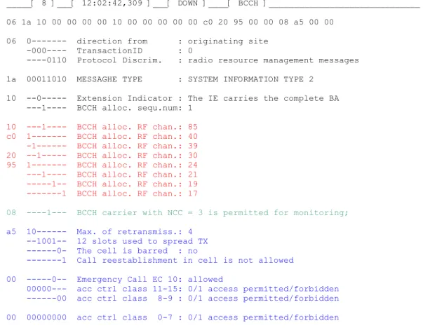
6.5 The message SYSTEM INFORMATION TYPE 2
The message SYSTEM INFORMATION TYPE 2 (table 3) consists of the neighbouring cells to be monitored, the permitted NCC and the declared rules for random access (see paragraph 6.4).
_____[ 8 ]___[ 12:02:42,309 ]___[ DOWN ]____[ BCCH ]______________________________ 06 1a 10 00 00 00 00 10 00 00 00 00 00 c0 20 95 00 00 08 a5 00 00
06 0--- direction from : originating site -000---- TransactionID : 0
----0110 Protocol Discrim. : radio resource management messages 1a 00011010 MESSAGHE TYPE : SYSTEM INFORMATION TYPE 2
10 --0--- Extension Indicator : The IE carries the complete BA ---1---- BCCH alloc. sequ.num: 1 10 ---1---- BCCH alloc. RF chan.: 85 c0 1--- BCCH alloc. RF chan.: 40 -1--- BCCH alloc. RF chan.: 39 20 --1--- BCCH alloc. RF chan.: 30 95 1--- BCCH alloc. RF chan.: 24 ---1---- BCCH alloc. RF chan.: 21 ---1-- BCCH alloc. RF chan.: 19 ---1 BCCH alloc. RF chan.: 17
08 ----1--- BCCH carrier with NCC = 3 is permitted for monitoring; a5 10--- Max. of retransmiss.: 4
--1001-- 12 slots used to spread TX ---0- The cell is barred : no
---1 Call reestablishment in cell is not allowed 00 ---0-- Emergency Call EC 10: allowed
00000--- acc ctrl class 11-15: 0/1 access permitted/forbidden
---00 acc ctrl class 8-9 : 0/1 access permitted/forbidden 00 00000000 acc ctrl class 0-7 : 0/1 access permitted/forbidden
Table 3: Message SYSTEM INFORMATION TYPE 2
The message System Information Type 2 does not appear in Picture 30.
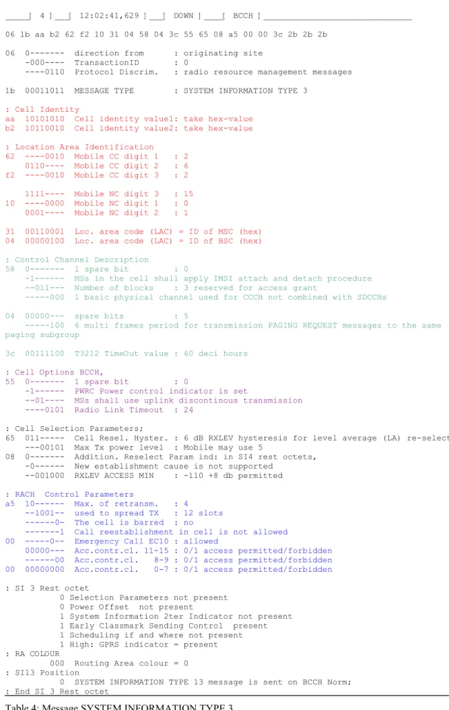
6.6 The message SYSTEM INFORMATION TYPE 3
6.6.1 The Information elements of SYS INFO 3
The first Information Element in the message SYSTEM INFORMATION TYPE 3describes the Cell Identity (the number of the BTS) consisting of two bytes.
The second IE, the Local Area Identification consists of the Country Code (in our case 262 for Germany; the Network Code 01 is the Operator t-Mobile (D1)) and the IDs of the MSC and the BSC.
The third IE represents the Control Channel Description.
- IMSI Attach (a somewhat strange term) means the Mobile registers to the VLR whilst logging into the network and deregisters from the VLR when releasing its channel. A user calling for that mobile therefore knows at once whether or not the mobile is logged in.
- The Number of blocks reserved for access grant specifies how many of the Paging Channels can be used for network access.
_____[ 4 ]___[ 12:02:41,629 ]___[ DOWN ]____[ BCCH ]______________________________ 06 1b aa b2 62 f2 10 31 04 58 04 3c 55 65 08 a5 00 00 3c 2b 2b 2b
06 0--- direction from : originating site -000---- TransactionID : 0
----0110 Protocol Discrim. : radio resource management messages 1b 00011011 MESSAGE TYPE : SYSTEM INFORMATION TYPE 3
: Cell Identity
aa 10101010 Cell identity value1: take hex-value b2 10110010 Cell identity value2: take hex-value : Location Area Identification 62 ----0010 Mobile CC digit 1 : 2 0110---- Mobile CC digit 2 : 6 f2 ----0010 Mobile CC digit 3 : 2 1111---- Mobile NC digit 3 : 15 10 ----0000 Mobile NC digit 1 : 0 0001---- Mobile NC digit 2 : 1
31 00110001 Loc. area code (LAC) = ID of MSC (hex) 04 00000100 Loc. area code (LAC) = ID of BSC (hex)
: Control Channel Description 58 0--- 1 spare bit : 0
-1--- MSs in the cell shall apply IMSI attach and detach procedure --011--- Number of blocks : 3 reserved for access grant ---000 1 basic physical channel used for CCCH not combined with SDCCHs 04 00000--- spare bits : 5
---100 6 multi frames period for transmission PAGING REQUEST messages to the same paging subgroup 3c 00111100 T3212 TimeOut value : 60 deci hours
: Cell Options BCCH,
55 0--- 1 spare bit : 0
-1--- PWRC Power control indicator is set
--01---- MSs shall use uplink discontinous transmission ----0101 Radio Link Timeout : 24
: Cell Selection Parameters;
65 011--- Cell Resel. Hyster. : 6 dB RXLEV hysteresis for level average (LA) re-selection ---00101 Max Tx power level : Mobile may use 5
08 0--- Addition. Reselect Param ind: in SI4 rest octets, -0--- New establishment cause is not supported
--001000 RXLEV ACCESS MIN : -110 +8 db permitted
: RACH Control Parameters
a5 10--- Max. of retransm. : 4
--1001-- used to spread TX : 12 slots ---0- The cell is barred : no
---1 Call reestablishment in cell is not allowed 00 ---0-- Emergency Call EC10 : allowed
00000--- Acc.contr.cl. 11-15 : 0/1 access permitted/forbidden
---00 Acc.contr.cl. 8-9 : 0/1 access permitted/forbidden 00 00000000 Acc.contr.cl. 0-7 : 0/1 access permitted/forbidden
: SI 3 Rest octet
0 Selection Parameters not present 0 Power Offset not present
1 System Information 2ter Indicator not present 1 Early Classmark Sending Control present 1 Scheduling if and where not present 1 High: GPRS indicator = present : RA COLOUR
000 Routing Area colour = 0 : SI13 Position
0 SYSTEM INFORMATION TYPE 13 message is sent on BCCH Norm; : End SI 3 Rest octet
- The Discontinuous Reception feature is designed to save energy.
Discontinuous Reception means the Mobile does not have to listen continuously when it is logged into the Paging Requests because the latter belong to Paging Groups. Therefore the Mobile only has to listen to Multi-frames belonging to its Paging Group.
A Mobile’s Paging Group is calculated from its IMSI. In the frame shown in Table 4 there are 6 multi-frame periods between the appearance of a Paging Group and the next time it has to be observed by the Mobile.
- The Timer 3212 is responsible for the Periodic Location Updating.In Table 4 this value is 6 hours.
The fourth IE is called Cell Options BCCH:
- If the Power Control Indicator (PWRC) is set, the Power of the mobile can be controlled by the BTS.
- Discontinuous Transmission is another method of saving energy.
Pauses often appear in conversation and it is favourable to switch off the transmitter during them. However, a hard switch-off appears to the subscriber at the other end of the line as an acoustic shock. To avoid this shock a so-called ‘comfort noise’ is transmitted during pauses in speech. In this case energy conservation comes from the transmission of a comfort noise frame every 480m instead of transmitting an (empty) speech frame every 20m.
- Radio link timeout appears when an active connection suddenly breaks down e.g. if the caller drives their car into an underground car-park. In this case it must be possible to define the end of the connection. This is done by counting the un-decodeable SACH-Frames. In the message shown this number is defined as 24.
The fifth IE is called Cell Selection Parameter:
- Let’s first have a look at the Parameter RXLEV ACCESS MIN. This defines the lowest RX level at which the Mobile’s receiver can decode signals without error. In this trace it is given as 102dB.
- A Cell Reselect Hysteresis is necessary when the mobile is transported along the border of two cells. If the mobile dips into the area of a neighbouring cell and finds a stronger signal there it initiates a handover. If it is transported a short time later back into its original cell, a second handover occurs and so on. To avoid such continuous switching between two
frequencies a Cell Reselect Hysteresis is defined, i.e. the network initiates a handover only if the field strengths in the new cell are greater than the measured field strengths in the old cell plus the Cell Reselect Hysteresis.
- The Max TX Power level is defined in the ETS 05.05 for GSM 900, see table 5. Power class : 1 2 3 4 5
Nominal max. output power: (20 W) 8 W (39 dBm) 5 W (37dBm) 2 W (33 dBm) 0,8 W (29 dBm) Table 5: Power class in GSM 900
6.6.2 The Rest Octet of SYS INFO 3
As shown in the headline of table 4 the octet string to be decoded is
06 1b aa b2 62 f2 10 31 04 58 04 3c 55 65 08 a5 00 00 3c 2b 2b 2b
As you can see in table 4, the decoding of all the octets is completed except for the boldly written digits in the string shown.
In GSM 4.08 Table 9.32 the SI 3 Rest Octetis defined to be mandatory (M) type of Value (V)
and length 4. The decoding is contained in paragraph 10.5.2.34. Let’s have a look at how this works:
Decoding is done bit by bit in the language Compact String Notation 1 CSN.1. There are no octet borders to be considered. Normally the octets which bear information are different from the 2b elements but it is possible that a part of the 2b octet may be included in the decoding of the Rest Octet.
Let’s have an example. The octets 3c 2b 2b 2b build the string (00111100 00101011 00101011 00101011) which is decoded as follows:
: SI 3 Rest Octet
0 Low:Selection Parameters not present
0 Power Offset not present
1 System Information 2nd Indicator present
1 Early Classmark Sending Control present
1 Scheduling if and where not present
1 High: GPRS indicator = present : RA COLOUR
000 Routing Area colour = 0 : SI13 Position
0 SYSTEM INFORMATION TYPE 13 message is sent on BCCH Norm; : End SI 3 Rest Octet
In the decoding scheme above there is the expression “High: GPRS indicator = present”. This derives from the rule { L | H <GPRS Indicator> } in paragraph 10.5.2.34 SI 3 Rest Octets (GSM 04.08 version 7.8.0 Release 1998).
The rule is as follows: if in the decoding algorithm the expression “L|H” appears, the octet to be decoded must be superimposed bit by bit by 2b = 00101011 with the operation X-OR. If in the position in which L | H is required the result is 1, the value H is true. In our example we have to calculate
3c = 00111100
2b = 00101011
As we can see at position 6 “1 x-or 0 = 1 = High”, while at position 1 “0 x-or 0 = 0 = Low”.
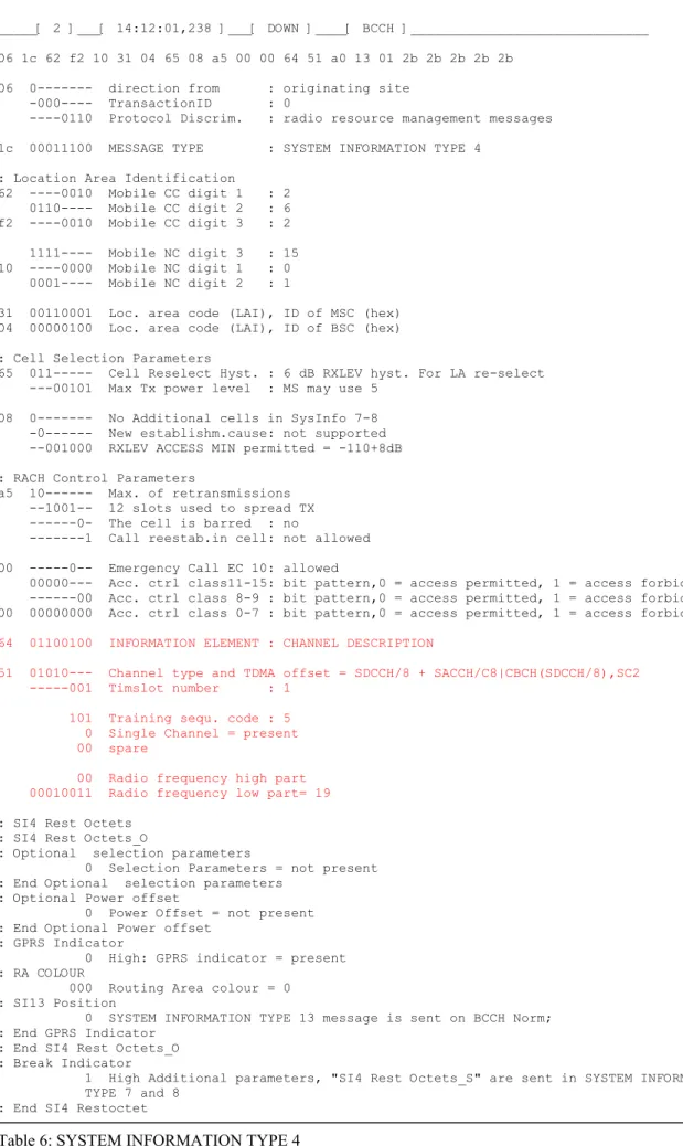
6.7 The message SYSTEM INFORMATION TYPE 4
The message SYSTEM INFORMATION TYPE 4 repeats the main Information Elements sent in the SYSTEM INFORMATIONS 1-3. These are:
- Location Area Identification, - Cell Selection Parameters,
- RACH Control Parameters.
The optional Information Element Channel Description is new. It describes where to find the CELL BROADCAST CHANNEL. This is a downlink channel which broadcasts information of common interest by SMS.
_____[ 2 ]___[ 14:12:01,238 ]___[ DOWN ]____[ BCCH ]______________________________ 06 1c 62 f2 10 31 04 65 08 a5 00 00 64 51 a0 13 01 2b 2b 2b 2b 2b
06 0--- direction from : originating site -000---- TransactionID : 0
----0110 Protocol Discrim. : radio resource management messages 1c 00011100 MESSAGE TYPE : SYSTEM INFORMATION TYPE 4
: Location Area Identification 62 ----0010 Mobile CC digit 1 : 2 0110---- Mobile CC digit 2 : 6 f2 ----0010 Mobile CC digit 3 : 2 1111---- Mobile NC digit 3 : 15 10 ----0000 Mobile NC digit 1 : 0 0001---- Mobile NC digit 2 : 1
31 00110001 Loc. area code (LAI), ID of MSC (hex) 04 00000100 Loc. area code (LAI), ID of BSC (hex) : Cell Selection Parameters
65 011--- Cell Reselect Hyst. : 6 dB RXLEV hyst. For LA re-select ---00101 Max Tx power level : MS may use 5
08 0--- No Additional cells in SysInfo 7-8 -0--- New establishm.cause: not supported --001000 RXLEV ACCESS MIN permitted = -110+8dB : RACH Control Parameters
a5 10--- Max. of retransmissions --1001-- 12 slots used to spread TX ---0- The cell is barred : no
---1 Call reestab.in cell: not allowed 00 ---0-- Emergency Call EC 10: allowed
00000--- Acc. ctrl class11-15: bit pattern,0 = access permitted, 1 = access forbidden ---00 Acc. ctrl class 8-9 : bit pattern,0 = access permitted, 1 = access forbidden 00 00000000 Acc. ctrl class 0-7 : bit pattern,0 = access permitted, 1 = access forbidden 64 01100100 INFORMATION ELEMENT : CHANNEL DESCRIPTION
51 01010--- Channel type and TDMA offset = SDCCH/8 + SACCH/C8|CBCH(SDCCH/8),SC2 ---001 Timslot number : 1
101 Training sequ. code : 5 0 Single Channel = present 00 spare
00 Radio frequency high part 00010011 Radio frequency low part= 19 : SI4 Rest Octets
: SI4 Rest Octets_O
: Optional selection parameters 0 Selection Parameters = not present : End Optional selection parameters
: Optional Power offset
0 Power Offset = not present : End Optional Power offset
: GPRS Indicator
0 High: GPRS indicator = present : RA COLOUR
000 Routing Area colour = 0 : SI13 Position
0 SYSTEM INFORMATION TYPE 13 message is sent on BCCH Norm; : End GPRS Indicator
: End SI4 Rest Octets_O : Break Indicator
1 High Additional parameters, "SI4 Rest Octets_S" are sent in SYSTEM INFORMATION TYPE 7 and 8
: End SI4 Restoctet
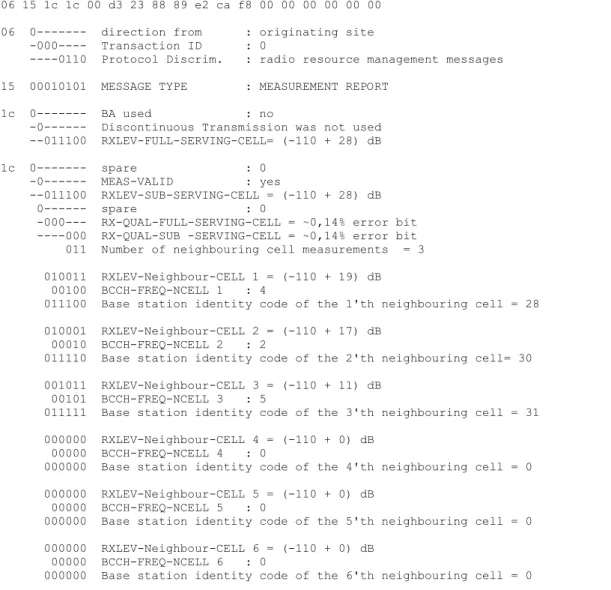
6.8 The message SYSTEM INFORMATION TYPE 5
The message SYSTEM INFORMATION TYPE 5 is sent by the BTS if the Mobile is in dedicated mode. The mobile receives in this message information about frequencies of neighbouring cells which are suitable for a handover and are therefore to be monitored. The term BA means BCCH ARFCN.
_____[ 13 ]___[ 18:44:31,133 ]___[ DOWN ]____[ SACCH ]_____________________________ 06 1d 00 00 00 00 00 00 00 00 00 00 00 c0 20 95 00 00
06 0--- direction from : originating site -000---- TransactionID : 0
----0110 Protocol Discrim. : radio resource management messages 1d 00011101 MESSAGE TYPE : SYSTEM INFORMATION TYPE 5
00 00--- Format Type : Bit Map 0 format
--0--- Extension Indicator : The IE carries the complete BA ---0---- BCCH allocation sequence number indication 0
c0 1--- BCCH alloc. RF chan.: 40 -1--- BCCH alloc. RF chan.: 39 20 --1--- BCCH alloc. RF chan.: 30 95 1--- BCCH alloc. RF chan.: 24 ---1---- BCCH alloc. RF chan.: 21 ---1-- BCCH alloc. RF chan.: 19 ---1 BCCH alloc. RF chan.: 17 Table 7: SYSTEM INFORMATION TYPE 5
6.9 The message SYSTEM INFORMATION TYPE 6
The message SYSTEM INFORMATION TYPE 6 is received by the Mobile in dedicated mode. This information is necessary for a possible handover.
_____[ 16 ]___[ 12:02:43,199 ]___[ DOWN ]____[ SACCH ]______________________________ 06 1e aa b2 62 f2 10 31 04 55 08 2b 2b 2b 2b 2b 2b 2b 00 00 08 1a
06 0--- direction from : originating site -000---- TransactionID : 0
----0110 Protocol Discrim. : radio resource management messages 1e 00011110 MESSAGE TYPE : SYSTEM INFORMATION TYPE 6
: Cell Identity aa 10101010 Cell identity value1, Hex Wert b2 10110010 Cell identity value2, Hex Wert
: Location Area Identification 62 ----0010 MCC digit 1 : 2 0110---- MCC digit 2 : 6 f2 ----0010 MCC digit 3 : 2 1111---- MNC digit 3 : 15 10 ----0000 MNC digit 1 : 0 0001---- MNC digit 2 : 1
31 00110001 Location area code (LAI), Number of MSC 04 00000100 Location area code (LAI), Number of BSC : Cell Options (SACH)
55 0--- 1 spare bit : 0 -1--- Power control indic.: is set
--01---- MSs shall use uplink discont.transmission ----0101 Radio Link Timeout : 24
6.10 The message SYSTEM INFORMATION TYPE 13
This message only appears if GPRS is possible in the cell. The mobile does not need to wait until theSYSTEM INFORMATION TYPE 13 appears: the Rest Octets in SYSTEM
INFORMATION TYPES 3 or 4 also say whether GPRS is available.
6.11 The message CHANNEL REQUEST
Please have another look at picture 30. In line 5, immediately after the message PAGING REQUEST has appeared, the Mobile sends a CHANNEL REQUEST.
The length of this message is only 8 bits. Three bits are used to express the cause of the Channel Request, five bits are left for a random number which serves as a distinguishing mark of the sender.
Possible causes for Channel Request are:
Emergency call 101 Answer to paging 100 Originating call… 111 Call re-establishing… 110 Location Updating 000 and so on.
To assign more than 5 causes, the number of random bits can be decreased to no less than 2.
6.12 The message IMMEDIATE ASSIGNMENT
With the message Immediate Assignment, negotiation about Radio Resources is initiated.
6.12.1 Assigning a single Channel
This message dedicates the mobile a Stand Alone Dedicated Control Channel SDCCH, a channel number, a timeslot number and a precise frame number.
Please have another look at Table 1 which shows a trace and a more detailed description of this message in paragraph 4.10.
6.12.2 Assigning frequency hopping
In GSM slow frequency hopping (SFH) is used, i.e. the transmission frequency remains the same during the transmission of a full burst. One of the reasons for the introduction of frequency hopping is frequency diversity.
As shown in picture 25, a message frame is encoded with a Fire Code which allows correction of 11 bit errors in the frame of 184 bits. The problem is the appearance of burst errors of more than eleven bits in the frame.
One solution to this problem is the additional coding with a convolutional code.
SFH offers another possibility of reducing errors: improved transmission is achieved by changing the frequency with every burst. I do not intend to have a closer look at this
behaviour because it requires knowledge about the theory of the propagation of radio waves. The Channel Description of frequency hopping consists of the following parameter:
- Mobile Allocation MA: the number of the frequency used during SFH.
- Hopping Sequence number HSN: a value between 0 and 63 which controls the Hopping Generator
MAIO and HSN together and determine the sequence of the frequencies and timeslots used after one another in the channel.
Two channels with the same HSN but different MAIO never use the same frequency on the same burst.
_____[ 30 ]___[ 11:36:27,504 ]___[ DOWN ]____[ CCCH ]______________________________ 31 06 3f 00 41 70 92 20 7b aa 01 01 07
31 00110001 Pseudo length : 49
06 0--- direction from : originating site -000---- TransactionID : 0
----0110 Protocol Discrim. : radio resource management messages 3f 0--- 1 spare bit : 0
-0--- Send sequence number: 0
--111111 MESSAGE TYPE : IMMEDIATE ASSIGNMENT : Page Mode
00 ----00-- 2 spare bits : 0
---00 Page mode : Normal paging : Dedicated Mode or TBF
0--- 1 spare bit : 0
-0--- Two messages assign.: No meaning --0--- Downlink assig to MS: No meaning
---0---- This message assigns a dedicated mode resource : Channel Description
41 01000--- Ch.type & TDMA offs.: SDCCH/8 + SACCH/C8|CBCH(SDCCH/8),SubChannel 0 ---001 Timslot number : 1
70 011--- Training seq. code : 3
---1---- Hopping Channel : RF hopping channel ----0000 MAIO (high) : 0
92 10--- MAIO (low) : 2 --010010 Hopping Seq. Number : 18
20 0010---- Establishing Cause : Answer to paging ----0000 Random Reference : 0
01111 15 = (T1) is coded as the bin.repr.of (Frame. Number div 1326) mod 32. 011101 29 = (T3) is coded as the bin. repr. of Frame Number mod 51.
01010 10 = (T2) is coded as the binary representation of FrameNumber mod 26. : The frame number, FN modulo 42432 can be calculated as 51x((T3-T2)mod 26)+T3+51x26xT1'
01 00--- 2 spare bits : 0
--000001 Timing advance value : 1 bit period 01 00000001 lgth of Mob.Alloc.IE : 1
07 ---1-- Mobile allocation RF chann.: Nr. 03 in the cell all.frequency list ---1- Mobile allocation RF chann.: Nr. 02 in the cell all.frequency list ---1 Mobile allocation RF chann.: Nr. 01 in the cell all.frequency Table 9: IMMEDIATE ASSIGNMENT dedicates a frequency hopping channel
6.13 The message PAGING RESPONSE
With the message PAGING RESPONSE the mobile sends a receipt of the information and orders given by the message IMMEDIATE ASSIGNMENT. It also describes its ciphering possibilities, hardware features and identity to the network (see table 10). Because there now begins the negotiation of the conditions with which the communication is to established, the connection on the air interface is switched into the protected mode.
_____[ 11 ]___[ 12:02:42,328 ]___[ UP ]___________________________________________ 06 27 04 03 23 19 01 05 f4 65 32 7d 20
06 0--- direction from : originating site -000---- TransactionID : 0
----0110 Protocol Discrim. : radio resource management messages 27 0--- 1 spare bit : 0
-0--- Send sequence number: value
--100111 MESSAGE TYPE : PAGING RESPONSE : Ciphering Key Sequence Number
04 ----0--- 1 spare bit : 0
---100 Ciph. key sequ. num.: 4 (7=no key available) 0000---- 4 spare bits : 0
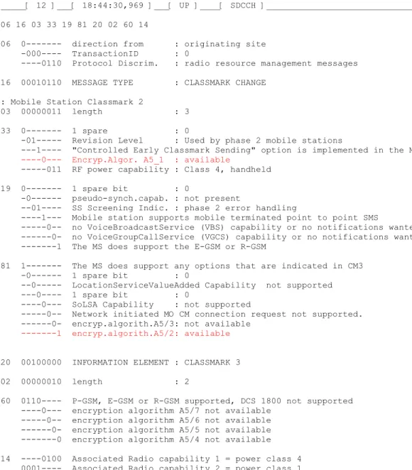
: Mobile Station Classmark 2 03 00000011 lgth of MS Cl.Mark2 : 3
23 0--- 1 spare : 0
-01--- Revision Level : Used by phase 2 mobile stations
---0---- "Controlled Early Classmark Sending" option is not implemented in the MS
----0--- Encryp.Algor. A5_1 : available
---011 RF power capability : Class 4, handheld 19 0--- 1 spare bit : 0
-0--- pseudo-synch.capab. : not present
--01---- SS Screening Indic. : phase 2 error handling
----1--- Mobile station supports mobile terminated point to point SMS
---0-- no VoiceBroadcastService (VBS) capability or no notifications wanted ---0- no VoiceGroupCallService (VGCS) capability or no notifications wanted ---1 The MS does support the E-GSM or R-GSM
01 0--- The MS does not support any options that are indicated in CM3 -0--- 1 spare bit : 0
--0--- LocationServiceValueAdded Capability not supported ---0---- 1 spare bit : 0
----0--- SoLSA Capability : not supported
---0-- Network initiated MO CM connection request not supported. ---0- encryp.algorith.A5/3: not available
---1 encryp.algorith.A5/2: available : Mobile Identity 05 00000101 length of Mob. ident: 5 f4 1111---- Identity Digit 1 : 15 ----0--- No. of ID digits : even ---100 Type of identity : TMSI/P-TMSI 65 01100101 Identity Digit 2,3 : take hex value 32 00110010 Identity Digit 4,5 : take hex value 7d 01111101 Identity Digit 6,7 : take hex value 20 00100000 Identity Digit 8,9 : take hex value
Table 10: The message PAGING RESPONSE
6.13.1 About the encryption of the Transport Channel
The first IE in the message PAGING RESPONSE is Ciphering Key Sequence Number. In order to understand this term we will have to deal with some ideas concerning the theory of ciphering. Picture 32 shows how a plain text can be ciphered. A modulo 2 random text is added to the plain text and the result is a random text.
The random text must be pure, i.e. it must stem for example from the noise of a radioactive source.
Because it is impossible for the sender and receiver simultaneously to have the same
radioactive source, we must seek to install a quasi-random source with a very large repetition time.
Picture 31: The principle of encryption.
Please bear in mind that the same frame number only appears every 3h, 28min, 53s, 750m. With this fact a quasi-random generator is built.
Picture 32: The principle of encryption with a quasi-random sequence.
As picture 32 shows, the random 114 bit sequence changes with every new frame number, therefore every burst is encrypted with a different random sequence.
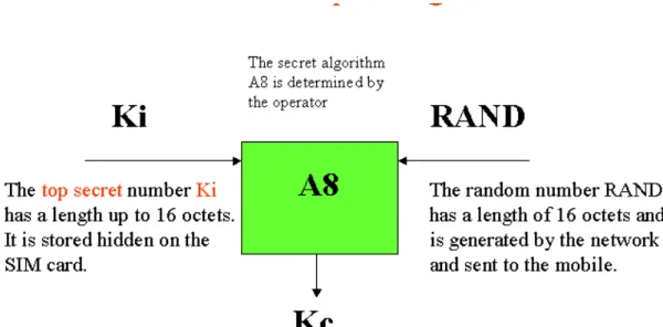
The random sequence is calculated from the 22 bit frame number and the 64 bit Ciphering Key (KC) by the algorithm A5/X (X=1…5).
The algorithm A5 is known by the manufacturers of mobiles and by the operators. From the called series of algorithms only A5/1 and A5/2 are used, A5/1 being the strongest .
Picture 33: The MM Information window of the OTDrivePC software
We will now consider how the Ciphering Key KC is calculated and how it is ensured that the
mobile and network use the same key.
Picture 34: The generation of a “password” (SRES)
First there is a highly secret number Ki which is stored hidden on the SIM card along with the algorithm A3. It is possible that every operator is using their own A3 but this does not matter because a user with a SIM card from operator D1 cannot have connections with users of the network of D2.
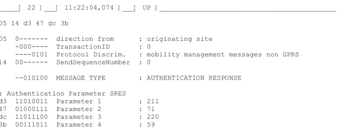
The network now sends the message AUTHENTICATION REQUEST and the Random number RAND which has a length of 16 octets.
This is like calling “Password” to a guard. In the same message the network sends the Ciphering Key Sequence Number CKSNto the mobile in order to assign the Kc to be used.