ORIGINAL ARTICLE
Dross formation and process parameters analysis of fibre laser
cutting of stainless steel thin sheets
Daniel Teixidor&Joaquim Ciurana&Ciro A. Rodriguez
Received: 7 August 2013 / Accepted: 27 December 2013 / Published online: 12 January 2014
#Springer-Verlag London 2014
Abstract The coronary stent fabrication requires a high-precision profile cut. Fibre lasers present a solution to accom-plish these requirements. This paper presents an experimental study of fibre laser cutting of 316L stainless steel thin sheets. The effect of peak pulse power, pulse frequency and cutting speed on the cutting quality for fixed gas type and gas pressure was investigated. A mathematical model based on energy balances for the dross dimensions was formulated. The dross height and the dross diameter were analysed and compared with the experimental results. This allows adjustment of the process parameters to reduce the dimensions of the dross deposited at the bottom of the workpiece during laser cutting of thin sheets.
Keywords Laser cutting . Fibre laser . Cardiovascular stent . Dross formation
1 Introduction
The laser cutting process has developed significantly over the past few decades and has become routine in sheet metal fabrication as a result of the attractive cutting velocities, excellent cut quality, processing flexibility as well as the widespread application possibilities that it affords [1].
One of its growing applications is the manufacturing of coronary stents for medical application. A stent is a wire mesh tube, which is deployed in a diseased coronary artery to provide smooth blood circulation. Stents can be either balloon expandable or self-expanding (using shape memory alloys). Stents are typically made from biocompatible materials such as stainless steel, nitinol (Ni–Ti alloy), cobalt–chromium, titanium, tantalum alloys, platinum–iridium alloy as well as polymer. The most commonly used is stainless steel. The laser key requirement for its fabrication is a small consistent kerf width, and this demands a constant beam quality and excellent laser power stability. The laser cut must have a good surface quality with a minimum amount of slag and burr to reduce post-processing, similarly the heat-affected zone (HAZ), and molten material recast needs to be small [2].
Fibre laser is seen as an efficient, reliable and compact solution for micro-machining in which heat-affected zone, kerf width and dross could be diminished to a minimum. This is because its important advantages as the combination of high beam power with high beam quality, small spot sizes, higher efficiency and almost free maintenance.
There are several research works, which use a fibre laser to study how the process parameters of the laser cutting affect the quality of the resultant surfaces. Kleine et al. [2] presented micro-cutting results in stainless steel samples of 100 and 150 μm where the kerf width and the surface quality were analysed. They studied also the laser conditions to minimise HAZ. They conclude that the fibre laser is capable to achieve very small diameters and small kerf widths presenting very similar features to those produced with a neodymium-doped yttrium aluminium garnet (Nd:YAG) laser. Muhammad et al. [3] investigate the basic characteristics of fibre laser cutting of stainless steel 316L tube and understand the effect of intro-ducing water flow in the tubes on minimising back wall damages and thermal effect. The influence of laser parameters upon cutting quality for fixed gas type and gas pressure was D. Teixidor
:
J. Ciurana (*)Department of Mechanical Engineering and Civil Construction, Universitat de Girona, Av. Lluis Santaló s/n, 17071 Girona, Spain e-mail: [email protected]
D. Teixidor
e-mail: [email protected] C. A. Rodriguez
Centro de Innovación en Diseño y Tecnologia, Tecnológico de Monterrey - Campus Monterrey, Monterrey, Mexico
investigated. Wet cutting enabled significant improvement in cutting quality. It resulted in narrower kerf width, lower sur-face roughness, less dross, absence of back wall damages and smaller HAZ. Laser average power and pulse width play a significant role in controlling the cutting quality. Increasing the pulse width increased beam–material interaction time, which increased the kerf width and surface roughness. Meng et al. [4] designed a cardiovascular stent cutting system based on fibre laser where the kerf width size was studied for different cutting parameters including laser output power, pulse length, repeat frequency, cutting speed and assisting gas pressure. Baumeister et al. [5] presented laser micro-cutting results for stainless steel foils with the aid of a 100-W fibre laser. Different material thicknesses were evaluated (100 to 300μm). Processing was carried out with cw opera-tion and with nitrogen- and oxygen-assisting gases. Besides the high processing rate of oxygen-assisted cutting, a better cutting performance in terms of a lower kerf width was obtained. Minimal kerf width of less 20μm was obtained with oxygen as the assisting gas. The kerf widths with nitrogen-assisted gas were generally wider. Scintilla et al. [6] presented results of ytterbium fibre laser cutting of Ti6Al4V sheets (1 mm thick) performed with argon as a cutting assis-tance gas. The effect of cutting speed and shear gas pressure on the HAZ thickness, squareness, roughness and dross at-tachment was investigated. The results show that, with in-creasing the cutting speed and then dein-creasing the heat input from 2 kW, an increase of HAZ and recast layer thickness occurs, up to 117μm. Powell et al. [7] developed an experi-mental and theoretical investigation into the phenomenon of ‘striation-free cutting’, which is a feature of fibre laser/oxygen cutting of thin section mild steel. The paper concludes that the creation of very low roughness edges is related to an optimi-zation of the cut front geometry when the cut front is inclined at angles close to the Brewster angle for the laser–material combination. Yan et al. [8] carried out both experimental and 3D FE modelling studies to analyse the effects of process parameters on temperature fields, thermal stress distribution and potential crack formation in high-power fibre laser cutting of alumina. Based on the numerical and experimental results, the mechanism of crack formation in laser fusion cutting was revealed, and crack-free cutting of thick-section alumina was demonstrated.
Other researchers studied the effect of process parameters on the fabrication of stents using different lasers on several materials like nitinol or stainless steel. Kathuria [9] described the precision fabrication of metallic stent from stainless steel (SS 316L) by using short pulse Nd:YAG laser. They conclude that the processing of stent with desired taper and quality shall still be preferred by the short pulse and higher pulse repetition rate of the laser, which is desired to reduce further the heat-affected zone as well as the surface roughness of the cut section. Pfeifer et al. [10] pulsed Nd:YAG laser cutting of
1 mm thick Ni–Ti shape memory alloys for medical applica-tions [shape memory alloy (SMA) implants]. They studied the influence of pulse energy, pulse width and spot overlap on the cut geometry, roughness and HAZ. They generated small kerf width (k=150–300μm) in connection with a small angle of taper (θ<2°). Compared to short- and ultrashort laser process-ing of SMA, high cuttprocess-ing speeds (v=2–12 mm/s) along with a sufficient cut quality (Rz=10–30 μm) were achieved. The drawbacks can be seen in the higher thermal impact of the laser–material processing on the SMA, resulting in a HAZ (dimension, 6–30μm) which affects the material properties and the reduced accuracy of the cutting process. Shanjin and Yang [11] presented Nd:YAG pulsed laser cutting of titanium alloy sheet to investigate the influences of different laser cutting parameters on the surface quality factors such as HAZ, surface morphology and corrosion resistance. The re-sults presented show that medium pulse energy, high pulse rate, high cutting speed and argon gas at high pressure help to acquire thin HAZ layers. Also in comparison with air- and nitrogen-assisted laser cutting, argon-assisted laser cutting comes with unaffected surface quality. Yung et al. [12] per-formed a qualitative theoretical analysis and experimental investigations of the process parameters on the kerf profile and cutting quality. They micro-cut thin Ni–Ti sheets with a thickness of 350 μm using a 355-nm Nd:YAG laser. The results showed that the kerf profile and cutting quality are significantly influenced by the process parameters, such as the single pulse energy, scan speed, frequency, pass number and beam offset, with the single pulse energy and pass number having the most significant effects. They obtained debris-free kerf with narrow width (≈25μm) and small taper (≈1°), and concluded that as the single pulse energy is increased and the laser beam velocity is decreased, the kerf width increases. Muhammad et al. [13] studied the capability of picosecond laser micromachining of nitinol and platinum–iridium alloy in improving the cut quality. Process parameters used in the cutting process have achieved dross-free cut and minimum extent of HAZ. Li et al. [14] reported investigations of fem-tosecond laser processing of Ni–Ti SMA using a fundamental wavelength of 775 nm from Ti:sapphire laser and its second and third harmonic irradiations. They developed a thermal influence-free optimal process to fabricate complex miniature SMA components. Huang et al. [15] studied the effect of a femtosecond laser machining on the surface and characteris-tics of nitinol. The results have produced surface roughness of about 0.2μm on nitinol. SEM and microstructural analyses revealed a HAZ smaller than 70 μm in depth, and a redeposited layer of about 7 μm exists on the machined surface. Raval et al. [16] machined a coronary stent after Nd:YAG laser cutting of 316LVM tubing and an assessment of its surface characteristics after electrochemical polishing. Finally, Scintilla and Tricarico [17] analysed the influence of processing parameters and laser source type on cutting edge
quality of AZ31 magnesium alloy sheets, and differences in cutting efficiency between fibre and CO2lasers were studied. They investigated the effect of processing parameters in a laser cutting of 1- and 3.3-mm thick sheets on the cutting quality. Their results showed that productivity, process effi-ciency and cutting edges quality obtained using fibre lasers outperform CO2laser performances.
Some authors studied the formation of the dross-developing analytical models in order to predict the shape of this melt material attached to the cutting edge. Yilbas et al. [18] formulated a mathematical model to predict the melt thickness and the droplet diameter. They compared it with experimental results of a CO2laser, obtaining a good fit. They found that the liquid layer thickness increases with increasing laser output power and reduces with increasing assisting gas velocity. Tani et al. [19] evaluated the 3D geometry of the cutting front of the melting film, considering mass, force and energy balance in an analytical model. Schuöcker et al. [20] presented a model for the dynamic behaviour of the liquid layer in laser cutting that predicts the melt ejection. They related the droplet ejection and the formation of periodic striations along the cut edges. Shuja et al. [21] simulated the temperature field and the phase change in the heated region. They examined the influence of laser power intensity and scanning speed on temperature field and melt depth.
The present work aims to investigate the characteristics of fibre laser cutting of stainless steel 316L-based cylindrical stents. The effect of laser cutting parameters on the cutting quality for fixed gas type and gas pressure was investigated. In machining stent geometries in stainless steel sheets, this work will contribute to understand the relation between the process parameters and the responses studied. The melt depth and dross size are mathematically modelled.
2 Methodology or experimental procedure
The laser source employed in this work was a Rofin FL ×50 fibre laser. This is a multimode laser capable of delivering up to 500 W power at a wavelength of 1,080 nm and a beam quality factor,M<1.1. The output can be modulated with a pulse frequency up to 5 kHz. The shortest pulse duration is 26μs. The process fibre used was 150μm in diameter, which was mounted in a focusing optics consisted of a Precitec Fine Cutting Head with a mm-length collimation lens and a 50-mm-focal-length objective. The focused spot size was calcu-lated to be 150μm. The coaxial assist gas nozzle had an exit diameter of 0.5 mm. The system is integrated in a Kondia CNC machine, which controls the movement ofX,YandZ stages for translating the work under the focused laser spot.
In this work, stainless steel 316L sheets of 100μm thick-ness were used as a workpiece material. These sheets were clamped and prestressed, with an approximately 2 N tension,
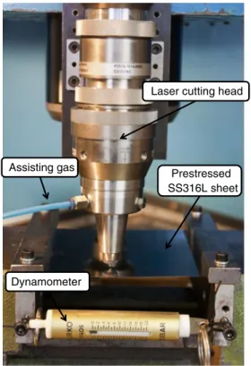
in order to avoid its deformation due the temperature. In this way, the stand-off distance is kept constant. Figure1presents the set-up of the system with the prestressed sheets and the laser cutting head in working position.
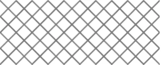
Preliminary screening experiments were carried out to determine the appropriate processing parameters levels to be used for the design of experiments. A full factorial design was used to determine the effects of peak pulse power, cutting speed and pulse frequency on the resultant cutting quality. The factors and factor levels utilised in this work are summarised in Table1. These factor levels results in a total of 27 unique factor level combinations. Nitrogen was used as the assist gas to protect the optics and to remove the molten material from the cut kerf. The pressure was 6 bar, the stand-off distance between the nozzle tip and the workpiece surface was 0.2 mm, and the pulse duration was 125 μs. These parameters were studied in the preliminary experiments and were decided to keep constant for all the experiments. In order to investigate the effects of the process parameters on the cutting quality factors, stent simple geometry [9], as presented in Fig. 2, was used as a cutting shape for the experi-ments. The samples have dimensions of 20 × 8.5 mm with strut width of 0.1 mm. With this flat geometry, a cylindrical structure could be formed by rolling and adhesive joining [22], but it is not the aim of this work. The cutting quality factors investigated were kerf width, surface rough-ness, dross deposition and heat effects.
Characterization of the laser cut samples was conducted using a confocal microscope Axio CSM 700 from Carl Zeiss.
Laser cutting head
Dynamometer
Prestressed SS316L sheet Assisting gas
The kerf width is measured, and the surface roughness is calculated using the microscope in conformity with the DIN EN ISO 4287 standard. The surfaces are also analysed in 3D images from the top and the cut edges. The measurements of the dross area were performed with an optical microscope Leica DMR-XA attached to Nikon F90 and Ricoh X-RX3000 camera bodies and digital video with a Sony DXC950-P of 3CCD camera for the collection of digital images. These images were numerically processed using the Quartz PCI© software, version 5.
3 Results and discussion
A total number of 27 stents were machined with laser cutting process by following the experimental plan discussed in the previous section. Kerf width, surface roughness and dross deposition were measured as quality factors. The surface roughness of four of the samples was not mea-sured, and the dross deposition was just measured in 20 of the geometries machined. Some statistical analysis with main effect plots will be presented in order to identify the relations between the process parameters and the responses.
3.1 Kerf width
Figure3shows the influences of cutting parameters upon the kerf width. It presents how each process parameter affects the kerf width. The results clearly show that the kerf width in-creased, as the peak pulse power, pulse frequency and cutting speed increased. As expected, the increase of peak pulse power and pulse frequency results in bigger kerf width. During the cutting process, the average power is proportional to these parameters and the pulse width. Thus, higher average power results in bigger kerf width. On the other hand, it would be expected that the increase of the cutting speed will lead to a reduction of the kerf width [3, 4]. As the cutting speed
reduces, the interaction time between laser beam and material increases which creates a larger kerf. However, the results present the opposite trend. This happens because the range used (250 to 500 mm/min) is not big enough to see the real trend of the relation between cutting speed and kerf width. Muhammad et al. [3] pointed out that the relation between both parameters increased until 1,000 mm/min where the kerf width started to decrease after this point. The kerf widths obtained in the experiments were within the range of 150 to 230 μm. Minimum kerf was obtained at lower peak pulse power of 200 W, lower pulse frequency of 3,000 Hz and lower cutting speed of 250 mm/min. Although the minimum achieved corresponds to the theoretical spot size calculated, it is clear that the experimental values obtained are bigger than this theoretical one. This was expected; Muhammad et al. [3] presented kerf width values 60 % above the theoretic spot size when the pulse peak power or the pulse frequency is in-creased, and Baumeister et al. [5] showed that increasing the energy the kerf width become 200 % higher than the focal diameter.
3.2 Surface roughness and striation on the cut surface Analysis was carried out to characterise the topography of the cut edges to determine the surface finish quality. The average roughness was measured in the midsection of the cut edge surface. Three measurements were taken in three different struts of each stent. The mean of these measures has been used as the experimental results for the surface roughness analysis. Figures 4 and 5 show the image of the cutting edge and the surface roughness profile obtained using the confocal microscope for two of the samples.
Figure6shows the relationship between the surface rough-ness and the laser parameters. Thus, the influence of the process parameters upon the surface roughness is presented. The surface roughness increased with the increasing peak Fig. 2 Stent geometry used on the laser cutting experiments
Table 1 Factors and factor levels of the design of experiments
Peak pulse power W 200 300 400
Pulse frequency Hz 3,000 4,000 5,000
Cutting speed mm/min 250 375 500
Fig. 3 Kerf width as a function of laser cutting parameters: peak pulse power, pulse frequency and cutting speed
pulse power. Although between the two levels seems to keep constant, clearly for the higher peak pulse power, the surface roughness presents its higher values. Although higher pulse frequency leads to higher average power, it results in better surface roughness due to high pulse overlapping. Lower cutting speed also increases the overlapping; thus, higher cutting speed results in worst surface roughness, as the results pointed out. The surface roughness ob-tained in the experiments was within the range of 0.547 to 1.447 μm. Although there are some parameter com-binations with higher values of surface roughness, this range is similar to the ones presented in other works [2,3]. MinimumRa was obtained at medium peak pulse power of 300 W, medium pulse frequency of 4,000 Hz and lower cutting speed of 250 mm/min.
The striation refers to periodic lines appeared on the cut surface. These periodic lines reflect the effect of the combina-tion of the laser beam moving along the surface, the pulse frequency and the pulse duration, generating pressure gradi-ents across the cut kerf and varying vaporisation fronts. This phenomenon created regularly spaced striations and increased the surface roughness on the cut surface. Thus, striation is directly related to the surface roughness and mainly affects the surface quality of the cut zones. The profiles of Figs.4and5
indicate that striation occurs, presenting different heights de-pending on the parameters. However, when looking at the images, it is not easy to see a clear pattern related to the striations. It seems that the molten material is deposited on the cut surface, modifying these striations generated from the laser beam movement.
3.3 Heat effects
Heat effect on the surrounding material is a critical factor in cutting thin materials, especially in medical device applica-tion. Small and thin materials are very sensitive to thermal distortion. Experiment results show that low average power reduced the thermal distortion. Thus, when pulse peak power and pulse frequency are higher, it resulted in a noticeable thermal effect and surface oxidation along the cut as clearly shown in Fig.7.
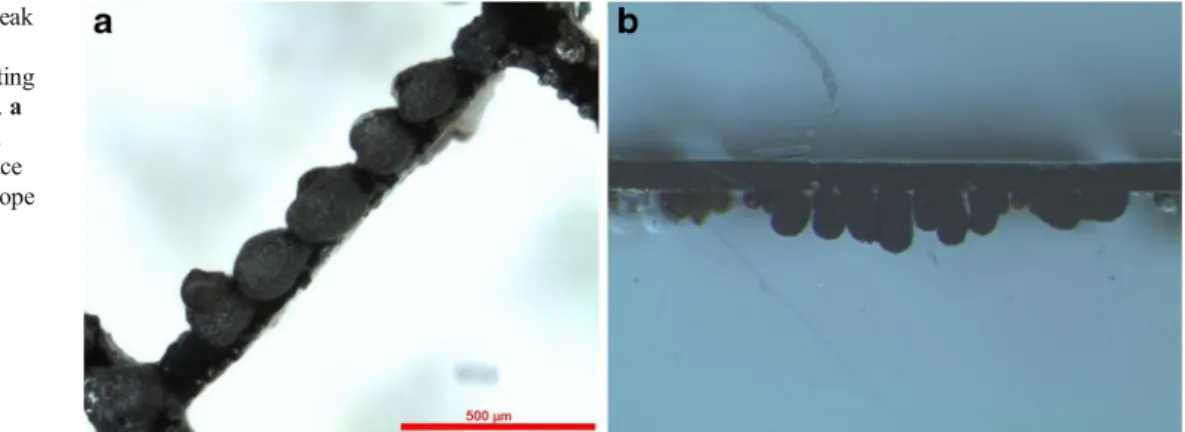
3.4 Dross deposition
The images of the cut surface with the dross formed were obtained from destructive tests in which the spec-imens were embedded in resin. Figures 8 and 9 present images from the cut surface and from the bottom of the geometry with the dross deposited for two different sam-ples. Clearly, there is much dross deposited in the cut edges of the samples. Depending on the combination of the pro-cess parameters, there are different amounts of it. The area was measured from the cut surface images in order to establish a relation between the input parameters and the dross formation.
The dross deposition has been measured for each stent in six different struts. The area of the dross has been taken from the upper part and lower part of the stent separately. The mean of the six measurements has been used as the value for the results analysis.
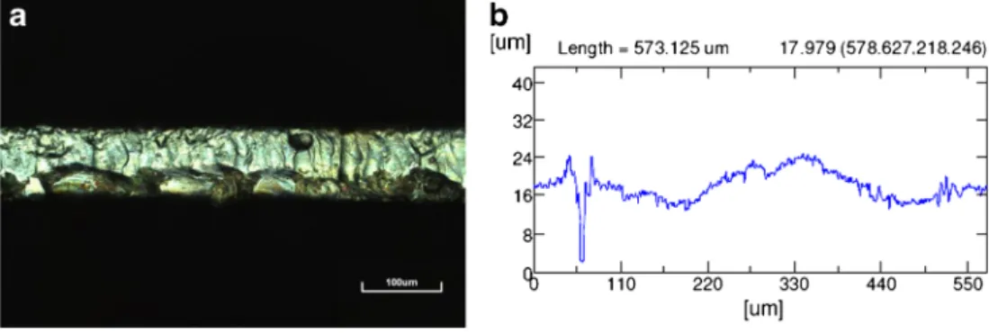
Fig. 4 Surface roughness of the cut surface for pulse power of 400 W, pulse frequency of 3,000 Hz and cutting speed of 500 mm/min.aImage of the cut surface from a confocal microscope (×219).bSurface roughness profile across the cut edge, whereRa=1,447
Fig. 5 Surface roughness of the cut surface for peak pulse power of 300 W, pulse frequency of 3,000 Hz and cutting speed of 375 mm/min.aImage of the cut surface from a confocal microscope (×219).bSurface roughness profile across the cut edge, whereRa=0,668
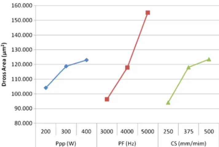
Figure10presents the dross deposition area as a function of the laser cutting parameters. Clearly, the samples processed were not free from dross. The molten material was not totally ejected out from the cut kerf and attached to the bottom side of the cut wall. The dross deposition area increased, as the peak pulse power, pulse frequency and cutting speed increased. The relation presented is similar to the one for the kerf width. If the peak pulse power and the pulse frequency increase, the average power increases, leading to more molten material. More molten material means that it is more difficult to remove by the assist gas. At the same time, as higher cutting speeds reduce the time, the gas is working on the same area; thus, the dross area gets bigger.
As can be seen in Fig. 9b, there are some cases where the sample presents material formation on the top of the struts. This material, rejected from the cutting zone, has been deposited on the sheet in a form of droplets. Thus, although these droplets are not always on the cut edge, the area of this material formed has been also measured following the same procedure de-scribed before.
In inert gas cutting, the energy solely came from the fo-cused laser beam. The presence of inert gas does not
contribute any additional energy to the cutting point (cooling of the cut zone may be resulted), thus producing high viscosity and high surface tension of molten material.
4 Mathematical modelling
As shown in the results, the dross deposition is quite impor-tant. Thus, a mathematical model is presented in order to predict the dimensions of this dross as a function of some of the laser cutting parameters. In this way, we can select the proper laser conditions to reduce the amount of dross. The height and the diameter of the dross deposited on the exper-imental samples were measured and compared with the model predictions.
4.1 Dross height
Considering the laser cutting as a transient process where a Gaussian laser beam strikes the surface of a substrate, moving in the positivexdirection with a uniform cutting speed. The laser beam intensity can be described by the Gaussian distri-bution as follows:
I xð ;yÞ ¼πRP2e−
x2þy2 ð Þ=R2
½ : ð1Þ
The process is considered as a continuous wave operation. The high repetition rates and the levels of cutting speed used during the experiments result in high overlapping between pulses (98.15–99.44 %), calculated as presented in [23], making the assumption of the continuous wave acceptable. The convection and con-duction are considered negligible.
Thus, the complex three-dimensional kerf, as shown in Fig. 11a, can be separated into finite surface elements de-scribed byxandydirections. For each element that is removed by melting, the energy balance can be described as follows Fig. 6 Surface roughness as a function of laser cutting parameters: peak
pulse power, pulse frequency and cutting speed
Fig. 7 Comparison of the thermal effect along the strut.a
Pulse peak power of 200, pulse frequency of 3,000 Hz and cutting speed of 250 mm/min.bPeak pulse power of 400, pulse frequency of 5,000 Hz and cutting speed of 500 mm/min
(the laser input energy is equal to the energy necessary for the phase change of the surface):
Ebeamδxδy¼Emeltδxδy: ð2Þ
The laser input energy is given by Ebeam¼ Z ∞ −∞ I xð ;y;zÞ ∂x v ¼ aP vpffiffiffiffiffiffiπRe −ðy2=R2Þ ð3Þ
whereais the absorptance of SS 316L at the Nd:YAG laser wavelength of 1.064 μm. Assuming that each element of dross is heated to the boiling point, the phase change energy is given by the following:
Emelt¼ρ CpsðTm−TiÞ þLmþCpmðTv−TmÞ
dHð Þy∂x∂y ð4Þ wheredH(y) is the dross height aty. Setting the energy balance yields aP vpffiffiffiπRe −ðy2=R2Þ ∂x∂y ¼ ρ CpsðTm−TiÞ þLm þCpmðTv−TmÞ dHð Þy ∂x∂y: ð5Þ
It is assumed that there is no fluid flow from neighbouringy direction regions. Then, the dross height can be obtained as
dHð Þ¼y aP
vpffiffiffiπRρ CpsðTm−TiÞ þLmþCpmðTv−TmÞ
e−ðy2=R2Þ
ð6Þ 4.2 Liquid layer thickness
Considering the melt layer generated at the solid surface during the steady laser heating process (Fig. 11b). The
influence of assisting gas on the cutting process needs to be modelled prior to dross diameter formulation. This is because the droplet diameter depends on the liquid layer. The energy balance with the melting process is considered in order to determine the liquid layer thickness.
E⋅beamþE⋅oxidation¼E⋅meltþE⋅condþE⋅conv ð7Þ
It is considered that the generated melt layer flows steadily in the direction of the assisting gas due to the drag force Fig. 8 Dross deposition for peak
pulse power of 300 W, pulse frequency of 3,000 Hz and cutting speed of 250 mm/min sample.a
Bottom image from an optical microscope (×50).bCut surface image from an optical microscope (×80)
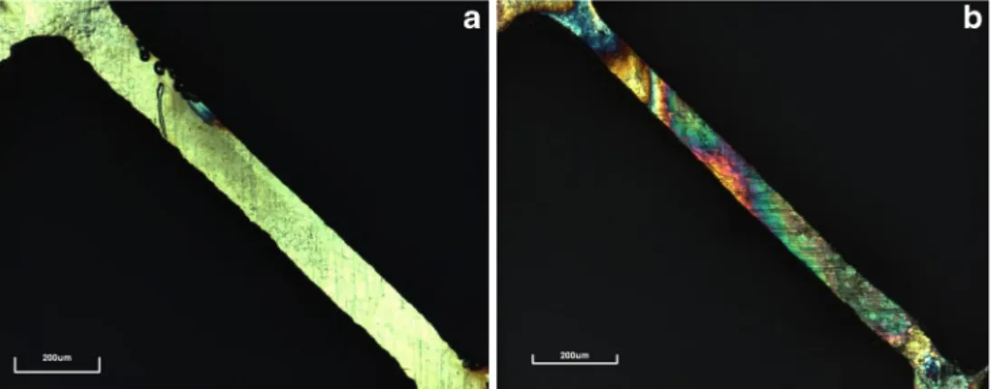
Fig. 9 Dross deposition for peak pulse power of 300 W, pulse frequency of 4,000 Hz and cutting speed of 500 mm/min sample.a
Bottom image from an optical microscope (×50).bCut surface image from an optical microscope (×80)
developed at the assisting gas–liquid interface. Because of the micrometric dimensions of the sheet thickness and the kerf width, it is assumed that the energy convected (Econv) from the surface to the assisting gas and the energy conducted (Econd) from the melted ma-terial to the solid substrate are minimally compared with the incident beam energy. Also, the use of nitrogen as an assisting gas reduces to a minimum exothermic reaction which would contributed to the energy transport process at the interface (Eoxidation).
The energy of the melting or phase change can be written as follows:
˙
E⋅meltþm⋅L CpsðTm−TiÞ þLmþCpmðTv−TmÞ
ð8Þ
where Cps and Cpm are the specific heat capacity of the material in the solid and liquid state, respectively, andTi,Tm andTvare the initial temperature, the melting temperature and the vaporisation temperature of the material, respectively. It is assumed that there is no evaporation of the material.˙mL is the
rate of mass generated from solid into liquid at the solid surface which in laser melting process, can be written as m⋅L¼
∂
∂tð Þ ¼ρV ρLvLA; ð9Þ
where vLis the velocity of the molten material, ρLis the density of the molten metal, and Ais the cross-sectional area. Setting the energy balance across the melt per unit area yields ˙ E⋅beam A ¼ ˙ E⋅melt A ð10Þ Therefore, vL¼ P AρL CpsðTm−TiÞ þLmþCpmðTv−TmÞ ð11Þ
Considering that the movement in the molten material towards the bottom of the workpiece is induced by a shear stress exerted by the assisting gas jet on the surface of the molten zone [20], the melt’s velocity is given by
vL¼sμL⋅τ L
ð12Þ where sL is the liquid layer thickness, μL is the dynamic viscosity of the molten metal, andζis the shear stress which is given by the following equation:
τ ¼ ffiffiffiffiffiffiffiffiffiffiffiffiffiffiffiffi ρGμGv3G z r ð13Þ Fig. 10 Dross deposition area as a function of laser cutting parameters:
peak pulse power, pulse frequency and cutting speed
whereρGis the density of the gas,μGis the dynamic viscosity of the gas,vGis the gas velocity, andzis the sheet thickness. Introducing Eqs. (6) and (7) into Eq. (4) yields
SL¼Aρ μLP L CpsðTm−TiÞ þLmþCpmðTv−TmÞ ρGμGv3G z −1=2 ð14Þ 4.3 Dross diameter
The dross formation depends on the liquid properties, such as viscosity, density and surface tension, as well as laser and cutting properties, such as assisting gas velocity, kerf size and liquid layer thickness. Moreover, a laminar flow of liquid film breaks up into droplets in an orderly and periodic manner. In practice, small satellite droplets can also be formed in between the main droplets due to high aerodynamic forces and insta-bilities associated with the breakup process. The formulation of drop formation based on the ligament disintegration can be appropriated to a laser cutting process. Droplet diameter (dD) formulated earlier is adopted herein [18]:
dD¼ 3π ffiffiffi 2 p sL 1þ 3μL ffiffiffiffiffiffiffiffiffi ρLsL p 1=6 ð15Þ
Equations (6) and (15) are used to compute the dross height and diameter in the cutting sections, respectively.
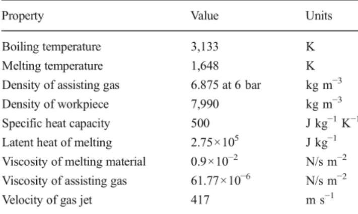
The dross height and diameter are analysed and compared with the experimental results. Table2gives the material and assisting gas properties. The diameter and height of the dross presented as experimental results are obtained by taking the average diameter of the measures taken in five different struts of each sample. The diameter measures are taken from bottom images in Fig.8a, and the height measures are taken from cut edge front images in Fig.8b.
Figure12presents the dross height predicted from Eq.6as a function of peak pulse power for different laser cutting
speeds. As in the previous case, the height of the dross increases with the increasing of the pulse peak power. In this sense, the predicted height and the average measured show similar tendencies. The predicted lines show that the height of the dross reduces when the laser cutting speed increases, and the experimental results present the opposite trend. In a laser milling process, lower cutting speed results in higher material removal because the incident laser beam lasts longer in the same area. However, in the laser cutting process, the presence of the assisting gas changes the trend. The lower the cutting speed, the more time is needed in working the gas to eject the molten material, reducing the height dross. Although there is no much literature relating the dross dimension with the cutting speed, this is in line with the results showed by Tani et al. [19]. Thus, the effect of the cutting speed in the model must be understood as the inverse of the reality. However, further research is necessary to ensure this relation.
Figure13shows the dross diameter predicted from Eq.15
with peak pulse power. Experimentally, obtained dross diam-eters are given for comparison. The higher pulse peak power results in bigger dross diameter. The increasing of power intensity increases the liquid film thickness, which in turn enhances the dross diameter. On comparing the predictions
Table 2 Workpiece and assisting gas properties used in the simulations
Property Value Units
Boiling temperature 3,133 K
Melting temperature 1,648 K
Density of assisting gas 6.875 at 6 bar kg m−3
Density of workpiece 7,990 kg m−3
Specific heat capacity 500 J kg−1K−1 Latent heat of melting 2.75×10⁵ J kg−1 Viscosity of melting material 0.9×10⁻² N/s m−2 Viscosity of assisting gas 61.77×10⁻⁶ N/s m−2
Velocity of gas jet 417 m s−1
0 50 100 150 200 250 300 350 400 150 200 250 300 350 400 450
Dross height (um)
Ppp (W)
CS = 250 mm/min CS = 375 mm/min CS = 500 mm/min CS = 250 mm/min exp
Fig. 12 Predicted and experimental dross diameter as a function of peak pulse power for different laser cutting speeds
0 50 100 150 200 250 100 200 300 400 500 Dross diameter (µm) Ppp (W) Predicted Experimental
Fig. 13 Predicted and experimental dross diameter as a function of peak pulse power
with the average dross diameter measured, both results were agreed to be quite good. However, both trend lines present different slopes. This may be associated to the assumptions made in the analysis.
5 Discussion
In laser cutting, the laser beam hits the workpiece at the current end of the cut kerf and heats the material. This process forms a thin liquid layer that is slightly inclined towards the vertical direction [24]. This liquid layer is then blown away by the drag forces from the fast-flowing gas stream and the pressure drop along the kerf depth. At the bottom of the kerf, the melt is thicker owing to flow from above, deceleration of the film and surface tension retarding the melt from leaving. The gas stream ejects the molten droplets at the base of the cut into the atmosphere. In fact, the problem of the removal of the dross from the bottom edge is further complicated by the wettability of the workpiece to the melt and the flow direction of the gas jet. Thus, cutting thin tin plate is difficult, owing to the dross clinging to the molten tin plate and the poorly directed gas jet which is emitted from a slot in a thin material [25].
The model presented in this paper is based on the energy balance between absorbed laser energy and that used to melt the material and focuses on the formation of droplets of molten material on the lower side of the workpiece caused by the shear stress exerted by the assisting gas jet on the surface of the molten zone. The authors claim that this stress leads to a downward flow within the molten metal and, thus, a build-up of droplets on the bottom side. These droplets separate from the workpiece when the surface tension of the droplet is overcome by the starvation pressure caused by said flow.
6 Conclusions
In this study, experimental results of fibre laser cutting of stainless steel 316L sheets were reported. The effect of peak pulse power, pulse frequency and cutting speed on the cutting quality for fixed gas type and gas pressure was investigated. The analysis showed that increasing the peak pulse power and the cutting speed increases the kerf width, surface roughness and dross deposition. However, the effect of the cutting speed needs further research because with higher values, the dross and the kerf width are expected to decrease. Higher pulse frequency values result in bigger kerf and dross but improves the surface roughness.
A mathematical model for the prediction of the dross height and dross diameter as a function of some of the process parameters was formulated. This helps to select
the proper laser parameters to reduce the amount of dross attached to the cutting edge.
Acknowledgments The authors would like to express their gratitude to the GREP research group from the UdG and to the Tecnologico de Monterrey for the facilities provided during the experiments. This work was partially carried out with the grant supports from the European Commission project IREBID (FP7-PEOPLE-2009-IRSES-247476) and the Spanish Science and Innovation Minister project TECNIPLAD (DPI2009-09852).
Glossary
List of the acronyms and symbols used in the paper Acronyms
CS Cutting speed HAZ Heat-affected zone PF Pulse frequency Ppp Peak pulse power
SEM Scanning electron microscopy SMA Shape memory alloy
Symbols
a Absorptance of SS 316L at a wavelength of 1.064μm A Cross-sectional area
Cpm Specific heat capacity of liquid phase Cps Specific heat capacity of solid phase dH Dross height
dD Dross diameter ρG Density of assisting gas ρL Density of molten material ρ Density of workpiece Lm Latent heat of melting R Laser beam spot radius Ra Roughness average sL Liquid layer thickness Tv Boiling temperature Tm Melting temperature Ti Ambient temperature ζ Shear stress
μL Dynamic viscosity of molten material μG Dynamic viscosity of assisting gas v Cutting speed
vG Velocity of gas jet z Sheet thickness
References
1. Tawari G, Sarin Sundar JK, Sundararajan G, Joshi SV (2005) Influence of process parameters during pulsed Nd:YAG laser cutting of nickel-base superalloys. J Mater Process Technol 170:229–239
2. Kleine KF, Whitney B, Watkins KG (2002) Use of fiber lasers for micro cutting applications in medical device industry. In: 21st International Congress on Applications of Lasers and Electro-Optics 3. Muhammad N, Whitehead D, Boor A, Li L (2010) Precision machine design. Comparison of dry and wet fibre laser profile cutting of thin 316L stainless steel tubes for medical device applications. J Mater Process Technol 210:2261–2267
4. Meng H, Liao J, Zhou Y, Zhang Q (2009) Laser micro-processing of cardiovascular stent with fiber laser cutting system. Opt Laser Technol 41:300–302
5. Baumeister M, Dickman K, Hoult T (2006) Fiber laser micro-cutting of stainless steel sheets. J Appl Phys A 85:121–124
6. Scintilla LD, Sorgente D, Tricarico L (2011) Experimental investiga-tion on fiber laser cutting of Ti6Al4V thin sheet. J Adv Mater Res 264-265:1281–1286
7. Powell J, Al-Mashikhi SO, Voisey KT (2011) Fibre laser cutting of thin section mild steel: an explanation of the‘striation free’effect. Opt Lasers Eng 49:1069–1075
8. Yan Y, Li L, Sezer K, Whitehead D, Ji L, Bao Y, Jiang Y (2011) Experimental and theoretical investigation of fibre laser crack-free cut-ting of thick-section alumina. Int J Mach Tools Manuf 51:859–870 9. Kathuria YP (2005) Laser microprocessing of metallic stent for
medical therapy. J Mater Process Technol 170:545–550
10. Pfeifer R, Herzog D, Hustedt M, Barcikowski S (2010) Pulsed Nd: YAG laser cutting of NiTi shape memory alloys—influence of pro-cess parameters. J Mater Propro-cess Technol 210:1918–1925
11. Shanjin LV, Yang W (2006) An investigation of pulsed laser cutting of titanium alloy sheet. Opt Lasers Eng 44:1067–1077
12. Yung KC, Zhu HH, Yue TM (2005) Theoretical and experimental study on the kerf profile of the laser micro-cutting NiTi shape memory alloy using 355 nm Nd:YAG. Smart Mater Struct 14:337–342
13. Muhammad N, Whitehead D, Boor A, Oppenlander W, Liu Z, Li L (2012) Picosecond laser micromachining of nitinol and platinum-iridium alloy for coronary stent applications. Appl Phys A 106: 607–617
14. Lia C, Nikumbb S, Wong F (2006) An optimal process of femtosec-ond laser cutting of NiTi shape memory alloy for fabrication of miniature devices. Opt Lasers Eng 44:1078–1087
15. Huang H, Zheng HY, Lim GC (2004) Femtosecond laser machining characteristics of nitinol. Appl Surf Sci 228:201–206
16. Raval A, Choubey A, Engineer C, Kothwala D (2004) Development and assessment of 316LVM cardiovascular stents. Mater Sci Eng A 386:331–343
17. Scintilla LD, Tricarico L (2013) Experimental investigation on fiber and CO2inert gas fusion cutting of AZ31 magnesium alloy sheets. Opt Laser Technol 46:42–52
18. Yilbas BS, Abdul Aleem BJ (2006) Dross formation during laser cutting process. J Phys D Appl Phys 39:1451–1461
19. Tani G, Tomesani L, Campana G, Fortunato A (2004) Quality factors assessed by analytical modelling in laser cutting. Thin Solid Films 453-454:486–491
20. Schuöcker D, Aichinger J, Majer R (2012) Dynamic phenom-ena in laser cutting and process performance. Phys Procedia 39:179–185
21. Shuja SZ, Yilbas BS, Momin O (2011) Laser heating of a moving slab: influence of laser intensity parameter and scanning speed on temperature field and melt size. Opt Laser Technol 49:265– 272
22. Shikida M, Yokota T, Naito J, Sato K (2010) Fabrication of a stent-type thermal flow sensor for measuring nasal respiration. J Micromech Microeng 20:055029
23. Teixidor D, Orozco F, Thepsonthi T, Ciurana J, Rodriguez CA, Özel T (2013) Effect of process parameters in nanosec-ond pulsed laser micromachining of PMMA-based microchannels at near-infrared and ultraviolet wavelengths. Int J Adv Manuf Technol 67:1651–1664
24. Tani G, Tomesani L, Campana G (2003) Prediction of melt geometry in laser cutting. Appl Surf Sci 208-209:142–147
25. Steen WM, Mazumder J (2010) Laser material processing, 4th edn. Springer