Proceedings of the
Fourth International Workshop on
Graph-Based Tools
(GraBaTs 2010)
Reachability Analysis on Timed Graph Transformation Systems
Christian Heinzemann, Julian Suck, Tobias Eckardt
12 pages
Guest Editors: Juan de Lara, Daniel Varro
Managing Editors: Tiziana Margaria, Julia Padberg, Gabriele Taentzer
Reachability Analysis on Timed Graph Transformation Systems
Christian Heinzemann, Julian Suck, Tobias Eckardt∗
Software Engineering Group Heinz Nixdorf Institute University of Paderborn Warburger Strasse 100 D-33098 Paderborn, Germany c.heinzemann|jsuck|[email protected]
Abstract:In recent years, software increasingly exhibits * properties like self-optimization or self-healing. Such properties require reconfiguration at runtime in order to react to changing environments or detected defects. A reconfiguration might add or delete components as well as it might change the communication topology of the system. Considering communication protocols between an arbitrary number of participants, reconfiguration and state-based protocol behavior are no longer inde-pendent from each other and need to be verified based on a common formalism. Ad-ditionally, such protocols often contain timing constraints to model real-time proper-ties. These are of integral importance for the safety of the modeled system and thus need to be considered during the verification of the protocol. In current approaches either reconfigurations or timing constraints are not considered. Existing approaches for the verification of timed graph transformation systems lack important constructs needed for the verification of state-based real-time protocol behaviors. As a first step towards a solution to this problem, we introduced Timed Story Driven Mod-eling [HHH10] as a common formalism integrating state-based real-time protocol behaviors and system reconfigurations based on graph transformations.
In this paper, we introduce a framework allowing to perform reachability analysis based on Timed Story Driven Modeling. The framework allows to compute the reachable timed graph transition system based on an initial graph and a set of timed transformation and invariant rules.
Keywords:Verification, Real-time Systems, Graph Transformation Systems, Reach-ability Analysis
∗ This work was developed in the course of the Special Research Initiative 614 – Self-optimizing Concepts and
Structures in Mechanical Engineering – University of Paderborn, and was published on its behalf and funded by the Deutsche Forschungsgemeinschaft.
1
Introduction
In recent years, software increasingly exhibits * properties like optimization or self-healing. Such properties require reconfiguration at runtime in order to react to changing environ-ments or detected defects. This causes a significant increase in the complexity of the software as also the reconfiguration process has to be controlled by the software. As software often operates in safety critical environments, it has to meet highest quality standards. Formal verification of safety and liveness constraints as well as verification of joint structural and behavioral constraints [KG07] address these requirements.
For embedded or real-time systems timing constraints for the software have to be taken into account during verification. Model Checkers like Uppaal1address these issues as they allow to check timed temporal logic formulas based on timed automata [Alu99]. Standard model check-ers for real-time systems, however, are not able to consider changing system topologies resulting from system reconfigurations (cf. Section6). Graph based model checkers like Groove [Ren08] support dynamic topologies, but are not capable of verifying timing constraints. Unfolding the state-space described by the graph transformation rules and using model checkers to verify the re-sult does not work for constraints referencing both, structural and behavioral parts of the system. Existing approaches combining graph transformations and real-time constructs (cf. Section6) come with restrictions that do not allow to model timed behavior to the extent that is needed for our systems. As a solution, we realize state-based real-time behavior using graph transfor-mation systems extended with timing constraints derived from timed automata. This enables us to integrate dynamic reconfiguration of the communication structure and to reuse the existing implementation for time computations from Uppaal.
In this paper, we introduce a framework for timed reachability analysis based on Timed Story Driven Modeling [HHH10]. In [HHPS10], reconfiguration and state-based behavior are analyzed independently. There, only pairs of automata were checked and an induction over the reconfig-urations of a regular architecture was used to show that no forbidden communication structures can arise. This ensures, that only such communication pairs can arise, that have been verified before. In this paper, we use Timed Story Charts [HHH10] as an explicit common formalism for the verification. This enables us to specify and verify arbitrary constraints that affect both, state-based protocol behavior and structural system state at the same time, e.g. that a reconfiguration may only take place if a certain communication protocol is in a specific state.
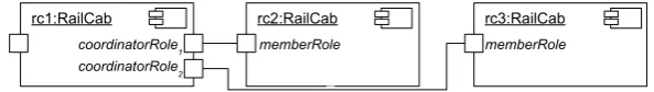
Example Scenario Our example scenario stems from the RailCab2project. The RailCab sys-tem consists of autonomous RailCabs that are fully controlled by software. RailCabs can form contactless convoys to reduce energy consumption. A convoy of RailCabs always needs one co-ordinating RailCab in order to prevent oscillation of the shuttle distances. A component instance model of a convoy with three RailCabs is shown in Figure1where RailCabrc1coordinates the convoy.
1http://www.uppaal.com/
rc1:RailCab rc2:RailCab rc3:RailCab coordinatorRole1
coordinatorRole2
memberRole memberRole
Figure 1: Component instances for the RailCab example.
Outline The remainder of this paper is structured as follows. First, we give a brief overview of Mechatronic UML. In Section3, we explain how a reachability analysis is performed using Timed Story Driven Modeling while Section 4 provides a description of the framework. We present the results of our evaluation in Section5and related work in Section6. Section7 con-cludes the paper.
2
Mechatronic UML
In this section, we briefly introduce MechatronicUML, an adaptation of the UML for modeling mechatronic systems. It provides extensions for modeling and verifying real-time systems and hybrid systems integrating continuous control components. Section2.1describes the system ar-chitecture of the system and Section2.2gives a short overview of Timed Story Driven Modeling with respect to MechatronicUML.
2.1 System architecture
We use a component-based system architecture based on MechatronicUML components. The communication between components is modeled with parameterized coordination patterns as introduced in [HHPS10]. Parameterized coordination patterns are used to specify 1 to n com-munication protocols between comcom-munication partners, called roles for cardinality 1 or multi rolesfor cardinalityn, respectively. Roles are instantiated at the ports of a component in order to provide the corresponding protocol.
The behavior of roles is specified by real-time statecharts [GB03]. In case of a multi role, a parameterized real-time statechart [HHPS10] is used to define the behavior of all sub-roles. Figure2shows an example of a parameterized pattern including the real-time statecharts defining the role behaviors.
The coordinatorrole sends an update event to the member role which answers with an
ac-knowledgement. The internal synchronization channelnextis used to synchronize the different sub-roles of the coordinatorRole as they are not independent in this scenario. The channel is parameterized with a parameter k referencing to thekth instance of the statechart. Thus, one sub-role triggers the next one in the example. Additionally, a propertyAG¬deadlockis specified for the pattern. Such properties may be verified for the pattern using the reachability analysis introduced in Section3.
coordinator member n ConvoyCoordination {ordered} waitUpdate sendAck update / / ack {c2} [c2 ≤ 150]
[1;1] [c2 ≤ 1] [1;1]
rtsc : memberRole | Clocks: c2
idle
sendUpdate awaitAck
nextk?
/ update ack / nextk+1! {c1}
[c1 ≤ 10] [10;10] [c1 ≤ 29]
[1;1] rtsc : coordinatorRole | Clocks: c1
Role behavior Role behavior
AG ¬ deadlock
Property
Figure 2: Definition of a Parameterized Coordination Pattern
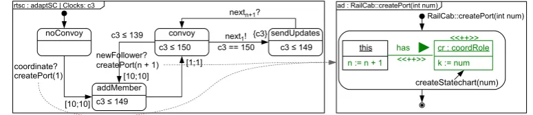
here. If the RailCab is chosen to coordinate, it changes its state toaddMember, thereby perform-ing the side effectcreatePort(1)of the transition. The side effect is a method of the component being specified by the story diagram [FNTZ00] on the right in Figure3. The side effect in this example simply creates a new port. The deadline[10; 10]of the transition denotes that this recon-figuration takes at least 10 time units and at most 10 time units. After reaching the stateconvoy, the invariant forces the statechart to switch to statesendUpdatesevery 150 time units, thereby triggering the firstcoordinatorRoleto send the update.
a
noConvoy convoy
coordinate? createPort(1)
createPort(n + 1)
sendUpdates next1!
c3 ≤ 150
{c3} c3 == 150 c3 ≤ 149
nextn+1?
addMember c3 ≤ 149 [10;10]
[10;10]
[1;1]
rtsc : adaptSC | Clocks: c3
this has cr : coordRole <<++>>
RailCab::createPort(int num)
n := n + 1
<<++>>
k := num
createStatechart(num)
ad : RailCab::createPort(int num)
newFollower? c3 ≤ 139
Figure 3: Adaptation Statechart for a Multi Port
2.2 Timed Story Driven Modeling
The Timed Story Driven Modeling [HHH10] approach is based on Timed Story Patterns and Timed Story Diagrams. Timed Story Patterns are a short-hand notation for timed graph transfor-mations [HHPS10,HHH10] that depict the left hand side and the right hand side in one graph. Elements being created (or deleted) by the transformation are labeled with<<++>>(or<<-->>). Timed graph transformations operate on timed graphs which contain clocks like timed au-tomata [Alu99], each being associated with a subgraph of the graph. The same clock can occur multiple times, once for each occurrence of the associated subgraph. Therefore, we use the term
clock instanceto denote the instances of a clock. The number of clock instances to be added to the graph, however, has to be finite, but it may vary during run-time. The representation of clock values is realized using clock zones [Alu99,BY03], as in timed automata.
and clock instance rules. A clock instance rule adds clock instances to the graph which are used by the transformation rules and the invariant rules to specify timed behavior. Transformation rules change the graph while invariant rules put a condition on the values of the clock instances of the timed graph. Due to space limitations, we only show how these rules are implemented in our framework in Section4.2.
Story diagrams [FNTZ00] extend UML Activity Diagrams by embedding graph transforma-tions specified by story pattern into the activities. We obtain Timed Story Diagrams by embed-ding Timed Story Patterns into the activities. To allow the execution of real-time statecharts using Timed Story Diagrams while preserving their semantics, we define Timed Story Charts [HHH10] on the basis of Timed Story Diagrams. The core idea is to represent the statecharts and their states as nodes of a graph and to provide graph transformation rules (Timed Story Di-agrams) specifying the state changes resulting from transitions. The currently active state of the statechart is represented by anActiveState-node. The transformation of real-time statecharts to Timed Story Charts has been partially automated [HSJZ10].
3
Reachability Analysis
The reachability analysis computes the Timed Graph Transition System (TTS) based on the given transformation rules and invariants. It represents the complete reachable behavior. In general, the TTS may be infinite. Thus, it cannot be guaranteed that the algorithm will eventually terminate for a given set of rules. This is a general problem when computing graph transition systems. The TTS can be defined as follows:
Definition 1(Timed Graph Transition System (TTS)) LetG be the set of all possible timed graphs,Ra set of transformation rules,I a set of invariant rules. The Timed Graph Transition System (TTS) is a triple(S,s0,T)whereSrepresents the set of states of the TTS,s0∈Sis the
initial state andT represents the transitions. A states∈Sis a tuples= (g,z)withg∈G andza non-empty clock zone over the clock instances contained ing. Ins0, all clock instances are 0.
There exists a transitiont froms1 tos2,s1
t
−
→s2, iff there exists a transformation ruler∈R
such thats2is a successor state ofs1.
The states are tuples consisting of a timed graph and the current clock interpretations rep-resented by a clock zone [Alu99]. The clock zone contains intervals for all clock instances representing the possible values as well as the differences between those values. The definition of the TTS is analogous to the definition of zone graphs [Alu99,BY03], the only difference is that the states contain a timed graph instead of an automaton location.
The computation starts with the initial graph and all clocks being 0. Then, possible successors are computed (see Definition2). The TTS contains transitions from a state to all its successors.
Definition 2(Successor State) Lets1= (g1,z1),s2= (g2,z2)states of a TTS.s2is a successor state ofs1iff
• there exists a transformation ruler∈Rsuch thatrtransformsg1into a graph isomorphic tog2and
The definition of a successor state is analogous to the one of timed automata [Alu99]. The only difference is that the change in the TTS results from the application of a transformation rule instead of an automaton transition. The computation of the successor clock zone remains the same. First, the clock zone is intersected against all constraints of invariant rules applicable tog1
denoted byI(g1). Then, time passes (⇑), which is implemented by removing the upper bounds of all clock instances (cf. [BY03]). Afterwards, the intersection against the invariants is repeated. Then, the resulting clock zone is intersected with the time guards of the applied transformation rule and the rules’ clock resets are executed. We restrict ourselves to guards of the formc∼n
wherecis a clock instance,∼∈ {<,≤,=,≥, >}, andn∈N, i.e., comparing the value of a clock instance with an integer. Invariants are further restricted to comparisons<and≤. Please note that there may exist more than one possible successor state for the same transformation rule as multiple matchings can be found.
In order to obtain a finite TTS, isomorphic states of the TTS are merged into one state. Two states are isomorphic, iff their graphs are isomorphic to each other and their clock zones are identical.
4
Verification Framework
We implemented the reachability analysis introduced in Section3 into our framework. In the following subsections, we introduce the general architecture of our framework at first. Second, we give an introduction how rules can be modeled, third, we explain how the TTS is computed, and finally, we give a brief idea of properties that can be checked using the framework. Part of the framework, not including the timing capabilities, has been shown in [HSJZ10].
4.1 Architecture
An implementation of a reachability analysis as specified in Section3requires additional rules which compute the TTS. Specifying concrete rules for the TTS generation for each example by hand is a tedious, error-prone task. Therefore, we provide a framework which requires the user to specify an initial graph and a set of rules, only. The remaining tasks, e.g. the application of rules, are integrated within the framework. Figure4shows the class diagram of the framework.
The abstract classReachabilityComputationencapsulates the whole functionality for comput-ing the timed graph transition system. It contains two abstract methodscreateInitialGraph()and
createRules(). Both have to be implemented by the user, whereas the former defines the initial
graph and the latter specifies which graph transformation rules are to be used for the reachability computation and which time constraints these rules have.
Graphs are represented by objects of the class StepGraph. They contain objects of the class
Node. To represent different types of nodes in a graph, subclasses ofNodecan be created. Edges between nodes are represented by associations.
sec-«JavaBean» Node tt H hC h ClockInstance
type: String valid: Boolean = true ClockInstance ( ):constructor toString( ):String
ClockInstance ( id:String , type:String ):constructor
InvariantRule
getCIsOfInvariants (step:StepGraph, clockInstances:HashSet<ClockInstance>)
ReachabilityComputation
DEBUG: Boolean = false
getApplicableInvariants ( step:StepGraph, invariants:HashSet<ClockConstraint> ) computeNormalizationVectorPerRule ( nv:HashMap<String, Integer> , rule:Rule ) computeNormalizationVector ( )
initialize ( ):StepGraph expand( step:StepGraph)
addAllClockInstances ( step:StepGraph):HashSet<ClockInstance> createRules ( )
unifyGraphs ( succ:StepGraph )
computeNormalizationVectorForStep ( step:StepGraph):HashMap<Clock,Integer> createInitialGraph ( ):StepGraph
processGraph( step:StepGraph, scc:HashSet<ClockConstraint> ,
resets:HashSet<Clock> , invariants:HashSet<ClockConstraint> ) computeReachableGraphs ( )
Rule
addClockInstances (step:StepGraph, clockInstances:HashSet<ClockInstance>)
StepGraph name: String toString( ):String
TransformationRule
apply (step:StepGraph, graphsAndCIs:HashMap<StepGraph, HashSet<ClockInstance>>) Clock
id: String = "" name: String = ""
SimpleClockConstraint clone ( ):Object
String cdFramework ciType * «usage» hasNode * 0..1 contains 0..1 «usage» has * hasInvariantRule * hasTransformationRule * graphs * todo 0..1 has * has 1 0..n uses
Figure 4: Class Diagram of the Verification Framework
tion contains more detailed information on how to implement transformation and invariant rules.
4.2 Modeling Rules
Timed graph transformation rules are represented by the abstract class TransformationRule. It contains an abstract method apply() which has to be implemented by subclasses to specify a concrete timed graph transformation rule. As parameters, this method receives a graph on which it is to be applied and a reference to a mapping. After the termination of the method, the mapping contains all reached successor graphs together with their respective clock instances used for the application of the rule.
create and deliver sent event
1: enqueue(ackEvent)
«create»
ackEvent: Event
name := "ack()"
conn: Connector sc_succ succ shPort: ShuttlePort coPort: CoordPort tgtQueue: EventQueue
Match the precondition and create the copy
sc: RailCab_RailCab_shuttlePort
source: State
name == "sendAck"
as: ActiveState
step succ: StepGraph := (StepGraph) step.copy()«create»
Execute transition
«create»
cis: HashSet<ClockInstance>
1: put(succ, cis)
succ as_succ: ActiveState sc_succ: RailCab_RailCab_shuttlePort source_succ: State graphsAndCIs target_succ: State
name == "waitUpdate" Trans_sendAck_waitUpdate_1::apply(step: StepGraph, graphsAndCIs: HashMap<StepGraph, HashSet<ClockInstance>>): Void
adTrans_sendAck_waitUpdate_1::apply() «create» contains source target hasSC hasQueue in contains in active «create» succ [each time] [end] index[as] index[source] index[sc] «create» active «destroy» active in
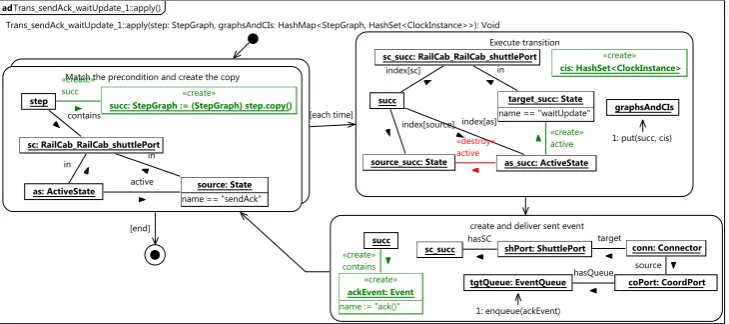
Figure 5: Story Diagram of the Transformation Rule, Modeling the Transition fromsendAckto
Figure5shows an implementation of the methodapply()modeling the transition from the state
sendAckto the statewaitUpdateof thememberrole statechart (cf. Figure2). The story diagram
consists of three activities. The first activity checks whether the rule is applicable, which is the case if thesendAck-state is the active state in the given statechart. If the rule is applicable, the second activity sets the active state fromsendAcktowaitUpdate. Finally, the third activity enqueues theack()-Event into the event queue of the statechart of the coordinator port.
Invariant rules are specified by subclasses ofInvariantRule. Subclasses implement the method
getCIsOfInvariant()which receives a graph on which the rule is to be applied and a set as
param-eters. After the termination of the method, the set contains all clock instances of the graph for which the time invariant specified by the rule is applicable.
convoy_1::getCIsOfInvariants(step: StepGraph, clockInstances: HashSet<ClockInstance>): Void
Match the invariant structure
state: State
name == "convoy"
step
sc: Statechart_for_RailCab_AdaptationStatechart
1: add(ci)
as: ActiveState
ci: ClockInstance
type == "c3"
clockInstances
{ ci <= 150 }
adconvoy_1::getCIsOfInvariants()
in
hasNode active
clockInstances
hasNode in
hasNode
[end]
Figure 6: Story Diagram of the Invariant Rule, Modeling the Invariant of Stateconvoy
Figure6shows a concrete example of a story diagram implementing the method
getCIsOfIn-variant(). The rule represents the invariantc3≤150 of the stateconvoyof the adaptation
state-chart (cf. Figure2). The invariant has to hold whenever the adaptation statechart’s active state is theconvoy-state. The activity matches to all structures which model exactly this situation. Whenever a matching structure is found, the corresponding clock instance is inserted into the set.
4.3 Computing the TTS
The verification of properties requires to compute the TTS according to Definition1by applying Algorithm1of our framework.
The algorithm maintains the TTS and a TODO list storing all states whose successors have not yet been computed. For each of these states, first all clock instance rules are applied (Line6). Then, all currently applicable invariants are collected in Line 7. The loop starting in Line 8 applies all transformation rules to the current graph by calling theapplyfunction. For each of the resulting successors, the successor clock zone is computed according to Definition2by the functionprocessGraph(Line11). Finally,unifyGraphsin Line12checks for isomorphisms and adds the state to the TTS and the TODO list.
All time computations, i.e. operations on clock zones, are performed using the Uppaal DBM (UDBM) library3. The C/C++-library, as originally implemented for the Model Checker Uppaal,
Algorithm 1Computation of the Timed Graph Transition System
1: functionCOMPUTETTS(Graph start, TransformationRules rules, InvariantRule inv)
2: TTS.add(start)
3: TODO.push(start)
4: whileTODO6=/0do
5: curState := TODO.pop()
6: addAllClockInstances(curState.g)
7: appInv := getApplicableInvariants(curState.g, inv)
8: for allr∈rulesdo .compute successor graphs
9: successors := r.apply(curState.g)
10: for alls∈successorsdo
11: processGraph(s, r)
12: unifyGraphs(s)
13: end for
14: end for
15: end while
16: returnTTS
17: end function
efficiently implements all necessary operations on clock zones (up or delay (⇑), intersection (∧), clock resets ([reset(r)])). Technically, we access the UDBM library using the provided Ruby binding in connection with a (local) client/server-communication between our Java implemen-tation and the Ruby implemenimplemen-tation. In Java, clocks, clock zones and clock constraints are represented as classes providing the corresponding operations on those instances as methods. This makes the binding to the UDBM library completely transparent for the developer and al-lows insertion and removal of clock instances which is not directly supported by the UDBM. In Java, clock instances can be created like normal objects. During runtime, a given clock zone is then transformed into ruby code as well as the desired operation is transformed. This ruby code is sent to the ruby server, which executes it and sends back the resulting clock zone as an encoded string. This string is finally transformed back into a clock zone object representing the result of the operation.
4.4 Verification of Properties
Currently, our framework only supports the verification of CTL (Computation Tree Logic) for-mulae having the formEFϕorAG¬ϕwhereϕis a graph invariant. Thus, it is possible to check whether a specific subgraph eventually occurs in the graph or to check whether a subgraph never occurs. Such properties are modeled as invariant rules containing the respective graph ϕ. A formulaEFϕ is fulfilled if the rule can be matched eventually to the graph. A formulaAG¬ϕ is not satisfied when a state exists in which the graph cannot be matched. In the TTS, a path from the initial state to the state in which the property does not hold serves as a counter-example.
Additionally, deadlock freedom, denoted byAG¬deadlockin Figure 2, may be verified. A deadlock corresponds to a state in the TTS with no outgoing transitions. Again, a path in the TTS from the initial state to the deadlock state serves as a counter-example.
5
Evaluation
We implemented the convoy coordination example shown in Figures2 and3 using the pattern and the statecharts. This resulted in 15 transformation rules and 13 invariant rules. In this case, we only needed three clock instance rules, one for each statechart, because we can create a statechart instance as a whole, along with all its clock instances.
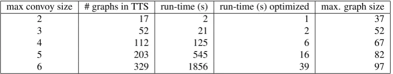
The number of RailCabs in a convoy was restricted to a maximum number in order to obtain a TTS for different maximum convoy sizes using our framework described in Section 4. The results are summarized in Table1.
Table 1: Evaluation results for different convoy sizes
max convoy size # graphs in TTS run-time (s) run-time (s) optimized max. graph size
2 17 2 1 37
3 52 21 2 52
4 112 125 6 67
5 203 545 16 82
6 329 1856 39 97
A convoy size of 2 corresponds to one leading RailCab and one convoy member RailCab, i.e., the leading RailCab has onecoordinatorRolestatechart instance. For each additional RailCab in the convoy, an additional instance is added. We computed the TTS for our example with a maximum convoy size of 6 RailCabs because the timing constraints in our example do not support larger convoys. We recently found a major performance problem in our implementation that yielded a significant improvement of our run-time as shown in Table1. The results indicate that the run-time grows exponentially in the number of reached graphs while the maximum graph size grows constantly as expected. The growth in run-time results from the high number of clock instances and the expensive timing computations which consume about 66% of the runtime. Additionally, our isomorphism check on graphs turned out to be inefficient [HSJZ10]. The timing computations along with the definition of isomorphic states cause a certain blowup in the number of reached states, as isomorphic graphs had to be expanded more than once because of differences in the clock zones.
6
Related Work
but annotated as an interval in which the transformation can be executed after a match has been found. In [THRB10], stochastic graph transformations are introduced. The simulation of these transformations incorporates a scheduling that is based on continuous time and executes a rule at a randomly generated point in time. A drawback of all approaches is their lack of support for flexible clock creation with resets and the specification of time guards at the same time. This, however, is needed for the system models we employ.
There exist some approaches for checking graph transformations without the possibility to consider timing constraints. Groove supports a reachability analysis on labeled graphs and checking graph based CTL formulas on the graph transition system [Ren08]. K¨onig et. al. [KK08] use an approximation technique that maps a possibly infinite graph transition system to finite Petri graphs and verifies the specified formula on this Petri graph structure. The inductive invariants introduced in [GS04] support infinite state spaces and only require a static analysis on the set of rules showing that a forbidden graph cannot be produced. It is not possible, however, to verify properties that cannot be depicted as a graph, like deadlock freedom, for example.
Bauer et. al. provide a verification approach for dynamic communication protocols [BSTW06] using over- and underapproximation of the system in order to verify LTL (Linear-time Tempo-ral Logic) formulas with first-order quantification on objects. The approach supports infinite numbers of communicating objects and finite message queues.
The timed model checker Uppaal provides the ability to check timed systems, but not the evo-lution of the system in terms of adding new statechart behaviors at run-time. The BIP framework [BS10] also provides real-time components and connectors with extensive analysis approaches, but does not support reconfigurations, either.
7
Conclusions
In this paper, we have shown a technique to perform a reachability analysis on Timed Story Diagrams, a dialect of graph transformation systems extended by the notion of time. We use Timed Story Charts as a common formalism to perform a reachability analysis for dynamic real-time communication protocols whose structural evolution is specified by graph transformations. As future work, we plan to extend our framework by the possibility to verify more complex timing constraints, as introduced in [KG07]. We will also investigate the possibility of applying existing abstraction and approximation techniques to the timed graph transformation systems in order to be able to handle larger state spaces and to obtain a more efficient verification procedure. Finally, we will try to fully automate the Timed Story Chart generation by adding generation of synchronizations and message recipients.
Bibliography
[Alu99] R. Alur. Timed Automata. In Halbwachs and Peled (eds.),Proc. of the 11th Intern. Conf. on Computer Aided Verification (CAV ’99), Trento, Italy. LNCS 1633, pp. 8–22. Springer, 1999.
[B ¨O10] A. Boronat, P. C. ¨Olveczky. Formal Real-Time Model Transformations in MOMENT2. In
[BS10] S. Bliudze, J. Sifakis. Causal semantics for the algebra of connectors. InFormal Methods in System Design. Volume 36(2), pp. 167–194. Springer, 2010.
[BSTW06] J. Bauer, I. Schaefer, T. Toben, B. Westphal. Specification and Verification of Dynamic Com-munication Systems. In6th Intern. Conf. on Application of Concurrency to System Design, 2006. ACSD 2006.IEEE Computer Society Press, 2006.
[BY03] J. Bengtsson, W. Yi. Timed Automata: Semantics, Algorithms and Tools. In Desel et al. (eds.),Lectures on Concurrency and Petri Nets. LNCS 3098, pp. 87–124. Springer, 2003.
[FNTZ00] T. Fischer, J. Niere, L. Torunski, A. Z¨undorf. Story Diagrams: A New Graph Rewrite Lan-guage Based on the Unified Modeling LanLan-guage and Java. In Ehrig et al. (eds.),TAGT’98: Selected papers. LNCS 1764, pp. 296–309. Springer, 2000.
[GB03] H. Giese, S. Burmester. Real-Time Statechart Semantics. Technical report tr-ri-03-239, Soft-ware Engineering Group, University of Paderborn, Germany, June 2003.
[GS04] H. Giese, D. Schilling. Towards the Automatic Verification of Inductive Invariants for Infinite State UML Models. Technical report tr-ri-04-252, Software Engineering Group, University of Paderborn, Germany, December 2004.
[HHH10] C. Heinzemann, S. Henkler, M. Hirsch. Refinement Checking of Self-Adaptive Embedded Component Architectures. Technical report tr-ri-10-313, Software Engineering Group, Uni-versity of Paderborn, Mar. 2010.
[HHPS10] S. Henkler, M. Hirsch, C. Priesterjahn, W. Sch¨afer. Modeling and Verifying Dynamic Com-munication Structures based on Graph Transformations. InProc. of the Software Engineering 2010 Conf., Paderborn, Germany. 2010.
[HSJZ10] C. Heinzemann, J. Suck, R. Jubeh, A. Z¨undorf. Topology Analysis of Car Platoons Merge with FujabaRT & TimedStoryCharts - a Case Study. In Gorp et al. (eds.),Transformation Tool Contest. Malaga, 2010.
[KG07] F. Klein, H. Giese. Joint Structural and Temporal Property Specification Using Timed Story Scenario Diagrams. InFormal Approaches to Software Engineering. LNCS 4422, pp. 185– 199. Springer, 2007.
[KK08] B. K¨onig, V. Kozioura. Towards the Verification of Attributed Graph Transformation Sys-tems. InICGT ’08: Proc. of the 4th Intern. Confe. on Graph Transformations. Pp. 305–320. Springer, Berlin, Heidelberg, 2008.
[LV10] J. de Lara, H. Vangheluwe. Automating the transformation-based analysis of visual lan-guages. InFormal Aspects of Computing. Volume 22(3), pp. 297–326. Springer, 2010.
[ ¨OM07] P. C. ¨Olveczky, J. Meseguer. Semantics and Pragmatics of Real-Time Maude.Higher-Order and Symbolic Computation20(1-2):161–196, 2007.
[RDV09] J. E. Rivera, F. Duran, A. Vallecillo. A graphical approach for modeling time-dependent behavior of DSLs.Visual Languages - Human Centric Computing0:51–55, 2009.
[RDV10] J. Rivera, F. Duran, A. Vallecillo. On the Behavioral Semantics of Real-Time Domain Spe-cific Visual Languages. In lveczky (ed.),Rewriting Logic and Its Applications. LNCS 6381, pp. 174–190. Springer, 2010.
[Ren08] A. Rensink. Explicit State Model Checking for Graph Grammars. InConcurrency, Graphs and Models. LNCS 5065, pp. 114–132. Springer, 2008.