Sharif University of Technology
Scientia IranicaTransactions A: Civil Engineering www.scientiairanica.com
Nonlinear seismic response of concrete gravity dams
due to foundation fault movement
M. Ghaemian
, A.H. Vafai and Z. Karimi
Department of Civil Engineering, Sharif University of Technology, Tehran, P.O. Box 11155-9313, Iran. Received 20 January 2013; received in revised form 4 December 2013; accepted 13 January 2014
KEYWORDS Concrete gravity dam; Nonlinear seismic response;
Foundation fault movement; Finite element method;
Split node technique; Dam-foundation-reservoir interaction.
Abstract. Not only should dams be evaluated for seismic shaking, but their capability to survive potential fault displacement in their foundations should also be assessed. Safety reviews of existing dams suggest that geological-seismic evaluation of some dam sites has failed to recognize the existence of possibly active faults. In this study, the nonlinear seismic behavior of concrete gravity dams, due to relative fault dislocation occurring in foundations, has been investigated. Two types of fault movement, including normal-slip and reverse-slip, have been considered. These two types, combined with the location of fault lines, with respect to the toe, middle, and heel of the dam base, angle of fault, and water elevation in reservoirs, which result in 36 types of model, have been considered. Results show that each type of fault can cause propagation of specic crack patterns, and the angle and location of the fault beneath the dam have a great eect on the amount of damage induced. The water pressure of the reservoir can also have increasing or even decreasing eects on the crack propagation rate. The existence of foundation fault movement beneath concrete gravity dams, depending on the condition of the problem, can cause rapid crack propagation in the dam body, jeopardize stability, and signicantly change the dam's dynamic response.
© 2014 Sharif University of Technology. All rights reserved.
1. Introduction
Generally, concrete dams have not been sited at loca-tions where faults are classied as active. However, there may be sites suitable for concrete dams where there is some possibility of fault displacement occurring underneath the dam. In addition, there may be situations where an existing dam was constructed over a fault thought to be inactive and later determined to be active, due to dierent approaches of classication. Also, some discontinuities may be observed during construction. In these cases, nonlinear analyses and
*. Corresponding author. Tel.: +98 21 66164242; Fax: +98 21 66014828
E-mail address: [email protected] (M. Ghaemian)
criteria will be required to assess the capability of the concrete dams to safely withstand fault displace-ment [1-5].
There is a method with simplied assumptions to investigate concrete stresses due to fault displacement in concrete gravity dams, the foundation model of which consists of a xed and movable block separated by elastic orthotropic elements [6]. However, this method does not represent a real fault movement in the foundation and introduces spurious forces or moments to the system. Also, some case studies to assess dam stability under foundation fault movement have been carried out [7-14].
In this study, a comprehensive investigation to as-sess the nonlinear seismic behavior of concrete gravity dams under the eect of foundation fault displacement,
1540 M. Ghaemian et al./Scientia Iranica, Transactions A: Civil Engineering 21 (2014) 1539{1548
depending on the dierent type, angle, and location of faults underneath the dam, have been carried out using nite element simulation [15,16].
2. Techniques of introducing fault into nite element
Several schemes for treating faults and cracks in bedrock have been proposed in the past [17-21]. A four node element of zero thickness is introduced parallel to the fault plane [22]. To model a slip event, shear stiness is assumed to be a very low value in the direc-tion of slippage. In another approach, the fault plane is dened by a series of pairs of adjacent nodes [23]. In the split node technique, displacement at nodes which are shared by dierent elements is normally the same for each element [24,25]. The mentioned methods are not well adapted to the description of a fault slip. Some of them result in inaccurate or unstable solutions, and avoid the manifestly incorrect procedure of specifying the absolute displacement of nodes at the fault plane (which would rigidly x the fault plane in space, prohibiting the normal elastic response of the grid and generating spurious stresses).
The technique which is of interest to us has been proposed by Melosh et al. They demonstrated that a modication of Jungels' split node technique can be implemented on a local level. The modication induced by this splitting can be contained in the load vector, so that the stiness matrix is not altered. They showed that no net forces or moments are applied to the grid when isoparametric elements are used [26]. In this technique, a single node, when referred to an element on one side of a fault, can have a displacement, u+, while it has a dierent displacement, u , when
referred to an element on the other side of the fault. The fault is thus dened by a single line of such split nodes. The nite element grid is the same whether the nodes are split or not. The foundation of the dam is considered as the domain, , with boundary and fault line , in which the eth element domain is denoted as e and its boundary is denoted as e (see
Figure 1).
All modications that should be undertaken to exert fault movement into the foundation are about adding the following statement to the consistent local load vector of the split nodes:
Fe p = Md X q=1 Xe
pqUqe; (1)
In the above equation, p and q are element (local) equation numbers, Md is the number of element nodes
times the number of components of the displacement dened at each n node, Keis the local stiness matrix
of the element, and Ue
q is relative fault displacement,
Figure 1. A general region of a continuum with boundary is subdivided into nonoverlapping elements e
with boundaries e. Nodes (black dots) denes the
intersection of elements. The subset (circled dots) are split nodes representing a fault or rock [26].
which are the same in magnitude but have dierent signs for each side of the fault.
3. Method
If the axis of a dam and fault line, both, lie in the same direction, two dimensional modeling of the dam-foundation-reservoir can be adopted. To consider the fault eect in the foundation beneath the dam, incre-mental nonlinear static analyses under loads induced by fault relative movement are carried out. Then, having cracks propagated and stresses induced on the dam monolith, nonlinear seismic analyses are assessed and the dynamic behavior of the dam is compared with conditions under which there is no fault movement in the foundation.
Two types of fault movement in two dimensional problems, including normal-slip and reverse-slip, have been considered. In order to investigate the concrete stresses under dierent angles of fault dislocation, faults with 45, 68 and 90 were located in the
foundation. Also, to see the eect of fault location, with respect to the dam base, the intersection of the fault line and the dam base should be at the heel, the middle and the toe. The eect of the water pressure of a reservoir was assessed by analyzing models under both full and empty reservoir conditions. Combining the above conditions resulted in 36 types of diverse model, which can mainly represent the eects of a foundation fault movement underneath the dam.
3.1. Finite element model
All models have been simulated by a 2D nite element computation method. For nonlinear analysis of the models, the NSAG-DRI (Nonlinear Seismic Analysis
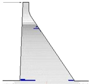
Figure 2. A nite element model of a
dam-foundation-reservoir system with foundation fault (dashed line).
Table 1. Properties of dam concrete. Elastic modulus 27580 MPa
Poisson's ratio 0.2 Unit weight 24357 N/m3
Static fracture energy 300 N/m Static tensile strength 2.4 MPa Dynamic magnication factor 1.2
Table 2. Properties of foundation rock. Elastic modulus 22400 MPa
Poisson's ratio 0.33 Unit weight 25928 N/m3
of Gravity dams including Dam-Reservoir Interaction) program, in plane stress mode, has been used.
Figure 2 demonstrates the nite element mesh of the dam-foundation-reservoir of a model with a normal-slip fault, with a 68 inclination, located at the middle
of the dam base and a full reservoir. Properties of the dam concrete and the foundation rock are shown in Tables 1 and 2.
4. Result of analysis and discussion
Incremental static nonlinear analyses of the Pine Flat dam were carried out for all models. The crack pattern of the sample condition of 68, a normal-slip
fault, located at the middle part of the dam base with a full reservoir, is demonstrated in Figure 3. In this set of gures, crack proles induced by the foundation fault movement have been depicted for specic values of the relative displacement of the fault.
Figure 3. Crack pattern propagated in dam body due to normal-slip fault displacement with 68inclination located
at middle part of the dam base and full reservoir during incremental nonlinear static analysis of foundation fault movement: (a) 1.5 mm, (b) 1.80 mm, (c) 3.69 mm, (d) 4.34 mm, (e) 6.20 mm, and (f) 10.14 mm relative displacement of the fault.
It can be seen that crack propagation initiates with a small value of fault dislocation. At the beginning of the fault movement, cracks propagate right at the intersection of the fault line and dam base and then dip in the dam body vertically and progressively. As the increment goes forward, a secondary crack prole at the upstream end of the base starts to propagate toward the downstream end, horizontally. When the faults relative displacement reaches a certain value, another crack propagation onset appears at the dam-foundation interface which spreads towards upstream, horizontally.
Figure 4 shows crack propagation in the monolith under the same conditions but with an empty reservoir. Compared to the full reservoir, the vertical crack propagation rate has been increased and, for this model, a secondary horizontal crack prole starts to appear at the downstream end of the dam-foundation intersection. By comparing empty and full reservoir analyses, it can be deduced that, for a certain length of vertical crack propagation, the dam with a full reservoir can experience more foundation fault movement.
1542 M. Ghaemian et al./Scientia Iranica, Transactions A: Civil Engineering 21 (2014) 1539{1548
Figure 4. Crack pattern propagated in dam body due to normal-slip fault displacement with 68inclination located
at middle part of the dam base and empty reservoir during incremental nonlinear static analysis of foundation fault movement: (a) 1.10 mm, (b) 2.60 mm, (c) 2.75 mm, (d) 3.12 mm, (e) 3.79 mm, and (f) = 5.10 mm relative displacement of the fault.
In Figures 5 and 6, models are the same as the above, respectively, for full and empty reservoirs, but the types of fault were changed to reverse-slip. When the reservoir is full (see Figure 5), as the nature of the fault movement changes, the crack pattern changes too, so that the damaged area is mainly in the dam-foundation intersection. In the beginning of incremental analysis, cracks start to propagate at the downstream, where the fault tends to move downward and induces tensile stresses on the dam concrete. Comparing this model to the model in which the reservoir is empty (Figure 6), it can be deduced that the water pressure mitigates the eect of fault movement at the upstream by producing tensile stresses at the upstream zone. Hence, in this model, water eects on
Figure 5. Crack pattern propagated in dam body due to reverse-slip fault displacement with 68inclination located
at middle part of the dam base and full reservoir during incremental nonlinear static analysis of foundation fault movement: (a) 0.70 mm, (b) 1.80 mm, (c) 2.80 mm, (d) 4.10 mm, (e) 5.50 mm, and (f) 7.00 mm relative displacement of the fault.
the upstream face may postpone the onset of upstream crack propagation to some next incremental steps. Obviously, the eect of water is up to a certain level and its eect decreases as the fault relative displacement increases.
Comparative and categorized results of other models are described and demonstrated as follows. 4.1. Eect of fault type
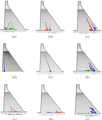
Despite the angle or location of a fault beneath the dam, signicant vertical crack propagation can be seen in the normal slip fault (Figure 7). For the same types of model but with a reverse-slip fault, cracks tend to appear at the lowest part of the monolith, and propagate right at the interface
Figure 6. Crack pattern propagated in dam body due to reverse-slip fault displacement with 68inclination located
at middle part of the dam base and empty reservoir during incremental nonlinear static analysis of foundation fault movement: (a) 0.50 mm, (b) 1.10 mm, (c) 1.80 mm, (d) 2.50 mm, and (e) 4.85 mm relative displacement of the fault.
Figure 7. Crack propagation pattern in normal-slip fault: (a), (b), and (c): 45fault with fault location in heel,
middle and toe of the dam base, respectively; (d), (e), and (f): 68fault with fault location in heel, middle and toe of
the dam base, respectively. (g), (h), and (i): 90fault
with fault location in heel, middle and toe of the dam base, respectively.
Figure 8. Crack propagation pattern in reverse-slip fault: (a), (b), and (c): 45fault with fault location in heel,
middle and toe of the dam base, respectively; (d), (e), and (f): 68fault with fault location in heel, middle and toe of
the dam base, respectively; (g), (h), and (i): 90fault with
fault location in heel, middle and toe of the dam base, respectively.
between the dam and the foundation, horizontally (Figure 8).
It can be inferred that, in normal-slip fault, the foundation tends to diverge along a horizontal direc-tion, so, it rips the dam body upward, corresponding to the fault movement. Where the type of the fault movement changes to reverse-slip, the foundation tends to converge along a horizontal direction, so the dam body experiences contracting forces. For this reason, a kind of separation occurs at the dam-foundation inter-face; the dam is heaved up, and horizontal crack proles would be resulted at the dam-foundation interface. 4.2. Eect of hydrostatic pressure
4.2.1. Normal-slip fault
When the reservoir is full, vertical crack propagation is faster. In the case of an empty reservoir, although the onset of crack propagation (in which the dam body is under tensile stresses at the upstream end of the dam foundation interface due to water pressure) is faster, vertical crack propagation is slower than in a full reservoir. Water pressure causes other forces to be exerted on the other axis and leads to decreased vertical but hastened horizontal crack propagation at the dam-foundation interface. As the fault relative
1544 M. Ghaemian et al./Scientia Iranica, Transactions A: Civil Engineering 21 (2014) 1539{1548
Figure 9. Eect of reservoir pressure on crack propagation for normal-slip fault type: (a), (c), and (e) are full reservoir; (b), (d), and (f) are empty reservoir. For each pair of full and empty reservoir foundation, fault relative displacements are identical.
displacement increases, the eect of water pressure dwindles (Figure 9).
4.2.2. Reverse-slip fault
At 68 and with reverse-slip fault, when the reservoir
is empty, at the right side of the fault, where the hanging wall of the fault moves downwards and leads to the induction of tensile stresses on the dam monolith, cracks initiate to propagate faster. Under the same conditions but in a full reservoir, the hydrostatic pres-sure of the reservoir mitigates some eects of the faults by inducing compressive forces, so that the onset of cracks appears at higher incremental steps of the fault movement at the toe (Figure 10). Therefore, the eect of water causes the cracks to propagate at the interface between the dam and the foundation at the toe.
Generally, if the monolith is assumed to be a cantilever beam, considering the location of its neutral axis, location, and type of fault, the resultant conse-quences of both water pressure and fault dislocation can have increasing or decreasing eects on crack propagation throughout the dam. An interesting result can be obtained from the condition of a 90 fault,
where the foundation moves only vertically and the fault is located at the toe. In this case, when the reservoir is empty, cracks tend to rip the dam body and go towards the crest. When the reservoir is empty, although the onset of crack propagation is faster due to shear stresses induced by water pressure on the mentioned cantilever beam, vertical cracks are inclined to change the direction of their growth and continue to propagate horizontally and faster towards upstream (Figure 10(e)).
Figure 10. Eect of reservoir pressure on crack
propagation for reverse-slip fault type: (a), (c), and (e) are full reservoir; (b), (d), and (f) are empty reservoir; for each pair of full and empty reservoir foundation fault relative displacements are identical.
4.3. Eect of foundation fault location
Fault location with factors such as type of fault and the uniform distributed weight of the dam on the foundation can, all together, aect the pattern, origin, starting point and mode of crack propagation (Figures 7 and 8). According to the supposed cantilever beam, the location of its neutral axis and the fault in the foundation, the portion of body weight on each side of the fault, and the upward or downward vertical dislocation of the fault sides, the crack pattern may be altered. In general, that side of the fault which carries a lower portion of the body weight of the dam is more vulnerable to damage. Comparing the results of models with the fault in the toe and models with the fault in the middle or heel of the dam, it can be inferred that, for the same value of relative displacement, the fault in the toe can be more harmful and causes more damage to be spread through the dam.
4.4. Eect of fault angle
A sharper angle can cause more damage to the dam (see Figure 11). Despite the location of the fault, the full or empty reservoir, and the type of the fault, it can be described that, for the same value of fault relative displacement, the sharper (less) angle of fault has a more horizontal component of displacement. In other words, the foundation experiences more conver-gent or diverconver-gent movement when the fault dislocates. Therefore, the sharper the angle of the fault is, the more is the eect on the dam. Obviously, the value of the fault angle can aect the direction of the vertical crack propagation in the dam, depending on reservoir conditions and meshing pattern.
Figure 11. Eect of fault angle on induced damage on the dam body: (a), (d), and (g): 90fault locating at heel,
middle and toe of the dam base, respectively; (b), (e), and (h): 68fault locating at heel, middle and toe of the dam
base, respectively; (c), (f), and (i): 45fault locating at
heel, middle and toe of the dam base, respectively. For each row of gures fault types and relative displacements are identical.
4.5. Connectivity in the interface between dam and foundation
In all the above analyses, there is a complete connec-tivity between the dam and the foundation elements in the nite element models, but material properties are dierent for dam concrete and bed rock. As the starting point of the cracks for small dislocations of fault occurred at this interface rapidly, this connectiv-ity was loosened by dening a row of partially cracked elements at the mentioned interface, and the analyses were renewed. For the same value of foundation, fault movement, slight changes in crack pattern and damage to the dam were observed during the second analyses. The superabundant weight of the dam does not allow any signicant slippage between the dam and the foundation or overturning the dam body; hence, the dam tends to crack.
4.6. Dynamic analysis of pine at dam
Dynamic analyses of the dam were carried out both before and after the foundation fault movement. So, the eects of cracks and damage induced by foundation fault movement on the dynamic response of the dam can be investigated. A model of a 68 normal-slip
fault, located in the middle part of the dam, with a
Figure 12. Crack proles in the dam body under seismic loading and no fault dislocation at T = 4:9 sec.
Figure 13. Crest displacement of the dam under seismic loading and no fault dislocation.
full reservoir, is discussed here. The foundation was massless and boundary conditions were changed as the dynamic analysis was carried out. Figure 12 shows crack proles under dynamic analysis of the above model with no fault movement at T = 4:9 sec under an earthquake produced by the same type of fault (normal-slip), and records are a projection of the fault plane with a PGA of 0.45 g. Figure 13 shows crest displacement during the analysis.
Figure 14 demonstrates crack patterns under only foundation fault movement, until relative fault movement reaches 3.50 mm. After propagating cracks through the dam due to foundation fault move-ment, dynamic analysis under the same earthquake records was carried out. Figure 15 depicts crack proles propagated through the dam under both foundation fault movement and earthquake loading. Comparative crest displacements under both con-ditions of dynamic analyses were depicted in Fig-ure 16.
According to the above gures, it can obviously be seen that considering foundation fault movement in the analysis not only changes the crack pattern in the dam body, but also changes the dynamic response of the concrete gravity dam.
1546 M. Ghaemian et al./Scientia Iranica, Transactions A: Civil Engineering 21 (2014) 1539{1548
Figure 14. Crack pattern propagated through the dam body under 3.5 mm foundation fault movement.
Figure 15. Crack pattern propagated through the dam body under both 3.5 mm foundation fault movement and seismic loading.
Figure 16. Crest displacement of the dam. Solid line: under both foundation fault movement and seismic loading; dashed line: under seismic loading and no foundation fault movement.
5. Conclusion
In this study, diverse models of foundation fault movement beneath a concrete gravity dam have been analyzed, and, according to the gures provided, the following conclusions may be drawn:
Foundation fault movement, even a small disloca-tion, can cause a signicant crack prole to prop-agate through the dam and seriously jeopardize its stability.
Relative displacement in the foundation due to normal-slip fault, depending on its magnitude, leads the dam monolith to be ripped to shreds, and, crack patterns are mainly vertical towards the crest. For the same model, but with reverse-slip fault movement, cracks are horizontal at the interface between the dam and the foundation, and fault movement tends to lift up the dam.
Water pressure at the upstream face may aect the pattern of crack propagation and has an increasing or decreasing eect on the magnitude of damage, de-pending on the type, angle, location and magnitude of the relative displacement of the fault.
The closer the fault line to the upstream or down-stream side of the dam is, the more damage there is on the dam body. Locating a fault line near the toe is the most vulnerable situation for certain dislocation of a fault movement.
Sharper fault angles, with respect to the horizontal axis of the foundation, can do more serious damage to the dam body.
The superabundant weight of the concrete gravity dam plays an important role in crack propagation and its pattern, because the dam tends to crack before any slippage between the dam and the foundation interface or an occurrence of overturn-ing.
Considering foundation fault movement in the dynamic analysis of a concrete gravity dam showed that relative fault displacement and its consequences, including induced stresses and crack propagation, can signicantly change the dynamic response of the dam. Hence, any foundation fault movement cannot be neglected in analyses.
References
1. Allen, C.R. and Clu, L.S. \Active faults in dam foundations", Bulletin of the Seismological Society of America, 64(3), pp. 555-570 (1974).
2. Bray, J.D. \Developing mitigation measures for the hazards associated with earthquake surface fault rap-ture", Seismic Fault Induced Failures, pp. 55-80 (2001).
3. Louderback, G.D. \Characteristics of active faults in the central coast ranges of California, with application to the safety of dams", Bulletin of the Seismological Society of America, 27(1), pp. 1-27 (1937).
4. Butler, D.K., Llopis, J.L. and Deaver, C.M. \Compre-hensive geophysical investigation of an existing dam foundation", Geoscience World, 8(8), pp. 10-18 (1989).
5. Butler, D.K., Jose, L.L., Thomas, L.D., Michael, J.W., Robert, F.C. and Gary, O. \Comprehensive geophysics investigation of an existing dam foundation: Engineer-ing geophysics research and development, Part 2", The Leading Edge, 9(9), pp. 44-53 (1990).
6. U.S. Army Corps of Engineers (USACE), Seismic Design Provision for Roller Compacted Concrete, EP 1110-2-12 (1995).
7. Ulusay, R., Aydan, O. and Hamada, M. \The be-haviour of structures built on active fault zones: Exam-ples from the recent earthquakes of Turkey", Structural Eng./Earthquake Eng., 19(2), p. 149 (2002).
8. Xu, W., Jiang, T., Zhao, Z., Long, Q. and Lei, S. \3 D numerical simulation of impact of key fault and fault enhancement on foundation rock mass of Guangzhao high gravity dam", Yanshilixue Yu GongchengXue-bao/Chinese J. of Rock Mech. and Eng., 25(6), pp. 1099-1105 (2006).
9. Boore, D.M. and Zoback, M.D. \Two-dimensional kinematic fault modeling of the Pacoima dam strong-motion recordings of the February 9, 1971, San Fernando earthquake", Bulletin of the Seismological Society of America, 64(3-1), pp. 555-570 (1974).
10. Leps, T.M. \The inuence of possible fault osets on dam design", Int. Water Power and Dam Construc-tion, 41(4), pp. 36-43 (1989).
11. Zan, Li. \Fault treatment at the abutments of longyangxia gravity-arch dam [J].", Chinese J. of Rock Mechanics and Eng., 4, p. 005 (1988).
12. National Research Council (USA) \Earthquake engi-neering of concrete dams: Design, performance and research", Panel on Earthquake Engineering for Con-crete Dams (1990).
13. Mgalobelov, Y.B. and Landau, Y.A. \Non-conventional concrete dams on rock foundations", Translated from Russian, Translation editor: Dr. G. Venkatachalam, General editor: Ms. Margaret Majithia, Published by: A. A. Balkema, P.O. Box 1675, 3000 BR, Rotterdam, Netherlands (1997).
14. Jansen, R.B., Advanced Dam Engineering for Design, Construction, and Rehabilitation, Kluwer Academic Publishers (1988).
15. Bathe, K.J. and Wilson, E.L., Numerical Method in
Finite Element Analysis, Prentice-Hall: Englewood Clis, New Jersey (1976).
16. Zienkiewicz, O.C., The Finite Element Method, 3rd Ed., McGraw-Hill: London (1977).
17. Jain, A., Verma, A.K., Vishal, V. and Singh, T.N. \Numerical simulation of fault reactivation phe-nomenon", Arabian J. of Geosciences, 6(9), pp. 1-10 (2012).
18. Vishal, V., Pradhan, S.P. and Singh, T.N. \Instability analysis of mine slope by nite element method ap-proach", Int. J. of Earth Sciences and Eng., 3(06), pp. 11-23 (2010).
19. Trivedi, R., Vishal, V., Pradhan, S.P., Singh, T.N. and Jhanwar, J.C. \Slope stability analysis in limestone mines", Int. J. of Earth Sciences and Engineering, 5(4), pp. 759-766 (2012).
20. Gupte, S.S., Singh, R., Vishal, V. and Singh, T.N. \De-tail investigation of stability of in-pit dump slope and its capacity optimization", Int. J. of Earth Sciences and Engineering, 6(2), pp. 146-159 (2013).
21. Singh, N., Pradhan, S.P. and Vishal, V. \Stability of slope in a re prone opencast mine in Jharia coaleld, India", Arabian J. of Geosciences, (Springer), 6, pp. 419-427 (2010).
22. Goodman, R.E, Taylor, R.L. and Brekke, T.L. \A model for the mechanics of jointed rocks", J. of Soil Mech. and Foundations, pp. 637-658 (1968).
23. Smith, A.T. \Time-depended strain accumulation and release at island arcs: implication for the 1946 Nakaido Earthquake", Ph.D. Thesis, Massachusetts Institute of Technology (1974).
24. Jungels, P.H. \Models of tectonic processes associated with earthquake", Ph.D. Thesis, California Institute of Technology, Pasadena, California (1973).
25. Jungels, P.H. and Frazier, G.A. \Finite element anal-ysis of the residual displacements for an earthquake rupture: Source parameters for the San Fernando earthquake", J. of Geophysical Research, 78(23), pp. 5062-5083 (1973).
26. Melosh, H.J. and Raefsky, A. \A simple and ecient method for introducing faults into nite element com-putations", Bulletin of the Seismological Society of America, 71(5), pp. 1391-1400 (1981).
Biographies
Mohsen Ghaemian is Associate Professor in the Civil Engineering Department of Sharif University of Technology, Tehran, Iran. His current research activities include the dynamic responses of gravity and arch dams, dam-reservoir-foundation interaction
1548 M. Ghaemian et al./Scientia Iranica, Transactions A: Civil Engineering 21 (2014) 1539{1548
eects, seismic response of dams due to non-uniform excitations and the nonlinear behavior of concrete dams.
Abolhassan Vafai, Ph.D., is a Professor of Civil Engineering at Sharif University of Technology. He has authored/co-authored numerous papers in dierent elds of Engineering: Applied Mechanics, Biomechan-ics, Structural Engineering (steel, concrete, timber and oshore structures). He has also been active in the area of higher education and has delivered lectures and published papers onchallenges of higher education, the
future of science and technology and humanresources development.
Zana Karimi is a Civil Engineering graduate (Hy-draulic Structures) of Sharif University of Technology, Tehran, Iran. His research involved the seismic re-sponses of concrete gravity dams under seismic loading and his thesis focused on the nonlinear behavior of concrete gravity dams considering the elasto-plastic be-havior of the foundation. His research interests include the eects of dam-foundation interaction, considering foundation faults.