PV MPPT Water Pump Controller
by
Jacob Lamkin
Senior Project
ELECTRICAL ENGINEERING DEPARTMENT
California Polytechnic State University
Table of Contents
Table of Contents 1
List of Tables 2
List of Figures 3
Abstract 4
Chapter 1. Introduction 5
Chapter 2. Background 8
Chapter 3. Design Requirements 11
Chapter 4. Design and Simulation Results 16
Chapter 5. Hardware Tests and Results 20
Chapter 6. Conclusion 32
References 34
Appendix A 36
Appendix B 40
List of Tables
Table 3-1: PV Water Pump Controller requirements and specifications 12
Table 3-2: Level 0 Description 14
Table 3-3: Level 1 Description 15
Table 5-1: Lab Data 23
Table 5-2: Hall Sensor Sensitivity Demo 24
Table 5-3: Lab Data Analysis 24
Table 5-4: Phase One Testing 29
List of Figures
Figure 1-1: Theoretical MPPT Chart 7
Figure 2-1: MPPT Control Loop Logic 10
Figure 3-1: Level 0 PV Powered Pump Controller 14 Figure 3-2: Level 1 PV Powered Pump Controller 15
Figure 4-1: Design Block Diagram 17
Figure 4-2: Design Schematic 17
Figure 5-1: Case Drilling 20
Figure 5-2: Modified Design Schematic 21
Figure 5-3: Test Fitting Components 21
Figure 5-4: Dual Source Power Supply 22
Figure 5-5: Output Current and Voltage Sensing 23
Figure 5-6: Final Project Layout 25
Figure 5-7: Outdoor Test Setup 26
Figure 5-8: Overcast Weather 27
Abstract
Chapter 1. Introduction
Water is far less accessible today than in the near past. Since 1900, about 70% of natural wetland area worldwide have been lost due to human activity, and 30% of the world's population lives in area regularly impacted by drought. 80% of all industrial and municipal wastewater are released to the environment without any prior treatment, meaning that access to underground water sources are key to acquiring cleaner water [1]. Not only is the need for water increasing, the ways in which it can be acquired are diminishing concurrently.
A source of power is needed to pump this water out of the ground. PV panels
(photovoltaic solar panels) are ideally suited to the task of off-grid daytime power generation: they have a simple setup, a long lifetime, and require little maintenance. Well-manufactured panels offset their environmental impact in only three to four years [2]. Over their 30 year lifetime, they produce over 20 times the energy embedded during manufacturing [3]. Off-grid solar power generation is increasingly admirable when compared to a gasoline generator. Gasoline generator systems not only continually produce waste, but also necessitate gas and large amounts of maintenance.
cell just enough to achieve maximum power transfer from it. This is displayed in the top graph in Figure 1-1, where it shows an example of the I-V characteristic of a PV at one operating
condition. As the voltage increases, the current stays constant. When the voltage reaches the knee region, the current starts to decrease. Beyond the knee region, the current drops
Chapter 2. Background
Water is far less accessible today than even in the near past. Since 1900, about 70% of natural wetland area worldwide have been lost due to human activity, and 30% of the world’s population lives in areas regularly impacted by drought. 80% of all industrial and municipal wastewater are released to the environment without any prior treatment, meaning that access to underground water sources are key to acquiring cleaner water [1].
Farming uses a notable amount of water, with the US consuming 88.5 million acre-feet of water for irrigation alone in 2013 [5]. This creates a need for efficient and reliable water pumping, as even marginal improvements greatly impact power usage. The PV Water Pump Controller focuses on delivering as much PV input power to the pump as possible. Solar
powered pumping competes with using a gasoline generator, another common power source for remote water pumps. A gasoline generator not only produces greenhouse gasses, but requires paying for fuel and maintenance. This is a problem, given that the average residence farming the US loses money annually [4]. Cheap irrigation poses a method to reverse this trend and lower costs for struggling farmers both domestic and abroad, but pumping water goes beyond just farming, for some it is necessary to have clean water. This problem is already being solved in southern Zimbabwe using low cost, low powered solar powered pumps to provide fresh water for both drinking and agriculture [1].
Using PV panels to power these pumps offers a large environmental advantage over other off grid energy sources, such as gasoline generators. Solar panels offset their
The problem this senior project addresses is integrating MPPT with a buck converter for high efficiency DC to DC conversion, and using it to drive a water pump from a PV source. This will address the need for smart converters to maximize efficiency in systems with a variable source, common in renewable power generation systems such as wind and solar. The intention of including a microcontroller to drive the buck converter revolves around how solar modules react to partial shading and low illuminance [7].
Because PV modules act as current devices until a very sharp drop off point, it is key to maintain operation of these devices as close to this corner of the I/V curve as possible. In a changing system, this can be achieved by following a closed loop control sequence that measures the changes in PV array voltage and current. Figure 2-1 provides a summary of the logic that is implemented into the system to perform MPPT. This control scheme allows the DC-DC converter to actively search for the MPP of a PV array under varying conditions
(temperature, sun position, etc.).
The concept of a microcontroller driven buck converter to drive a DC pump directly from a PV module has been explored by Oi in his thesis [8]. This report discusses the theory of pairing a microprocessor with a buck converter for this purpose, but a system was not
Chapter 3. Design Requirements
Customer Needs Assessment
“PV Water Pump Controller” customer base needs include low cost, autonomous operation, simple set up, high efficiency, and lightweight. The target market encompasses low income farmers and other individuals, with use cases including irrigating crops, pulling water from wells, and creating running water. The customer needs of the “PV Water Pump Controller” revolve around setup and operation possible for a low income non-technical individual. The low cost requirement explains itself. The device’s use case requires efficiency lest poor performance offset the low cost. The necessity for simple setup and autonomous operation arise from the expectation that the target customer possesses little technical skill. Device weight matters, because single person assembly allows greater accessibility.
Requirements and Specifications
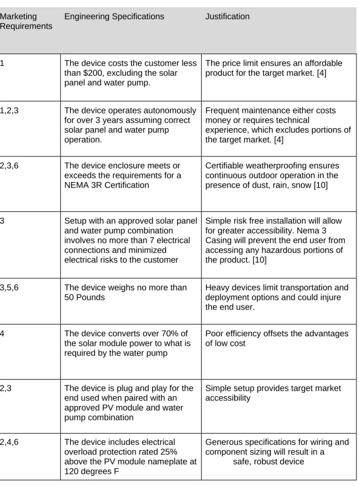
TABLE 3-1: PV Water Pump Controller requirements and specifications Marketing
Requirements
Engineering Specifications Justification
1 The device costs the customer less than $200, excluding the solar panel and water pump.
The price limit ensures an affordable product for the target market. [4]
1,2,3 The device operates autonomously for over 3 years assuming correct solar panel and water pump operation.
Frequent maintenance either costs money or requires technical
experience, which excludes portions of the target market. [4]
2,3,6 The device enclosure meets or exceeds the requirements for a NEMA 3R Certification
Certifiable weatherproofing ensures continuous outdoor operation in the presence of dust, rain, snow [10]
3 Setup with an approved solar panel and water pump combination involves no more than 7 electrical connections and minimized electrical risks to the customer
Simple risk free installation will allow for greater accessibility. Nema 3 Casing will prevent the end user from accessing any hazardous portions of the product. [10]
3,5,6 The device weighs no more than 50 Pounds
Heavy devices limit transportation and deployment options and could injure the end user.
4 The device converts over 70% of the solar module power to what is required by the water pump
Poor efficiency offsets the advantages of low cost
2,3 The device is plug and play for the end used when paired with an approved PV module and water pump combination
Simple setup provides target market accessibility
2,4,6 The device includes electrical overload protection rated 25% above the PV module nameplate at 120 degrees F
Generous specifications for wiring and component sizing will result in a
6 The device is installed with correct grounding and bonding to avoid electrifying the water source or user. NEC 680 pertains to pools, and will be followed short off GFCI shut-off. [13]
Electrifying a water source is a worst case scenario for this device and must be avoided for user safety. NEC 680.26(C) Bonding and 680.7 general water equipment safety guidelines shall be followed. [11]
2,3 The device’s external LED
indicates operating status: active, inactive, or fault.
A color coded LED output transcends language barriers and allows for simple field troubleshooting 3 The device’s case has mounting
points compatible with C channel couplings
Universally used C channel provides installation flexibility
Marketing Requirements 1. Low Cost
2. Autonomous Operation 3. Simple Setup
4. High Efficiency 5. Light Weight 6. Safety
Level 0 Block Diagram
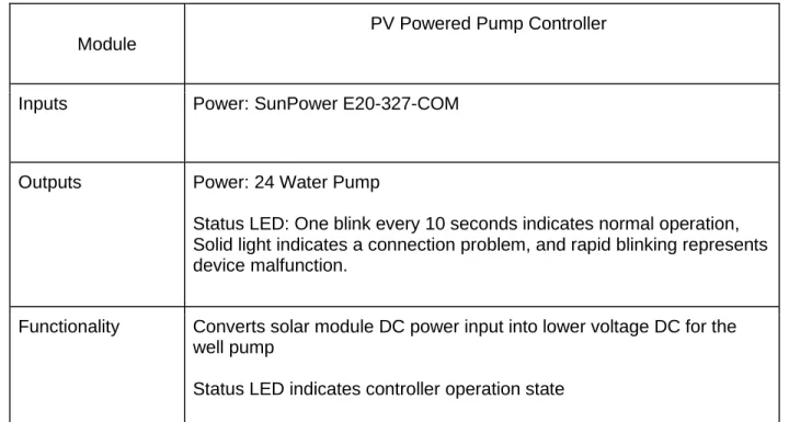
Figure 3-1: Level 0 PV Powered Pump Controller
Table 3-2: Level 0 Description
Module
PV Powered Pump Controller
Inputs Power: SunPower E20-327-COM
Outputs Power: 24 Water Pump
Status LED: One blink every 10 seconds indicates normal operation, Solid light indicates a connection problem, and rapid blinking represents device malfunction.
Functionality Converts solar module DC power input into lower voltage DC for the well pump
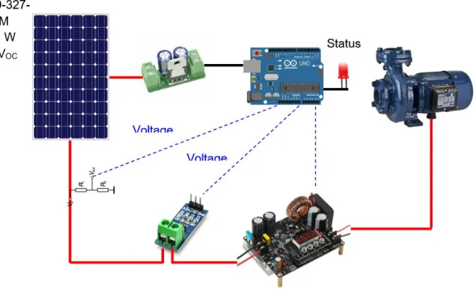
Figure 3-2: Level 1 PV Powered Pump Controller
Level 1 Block Diagram
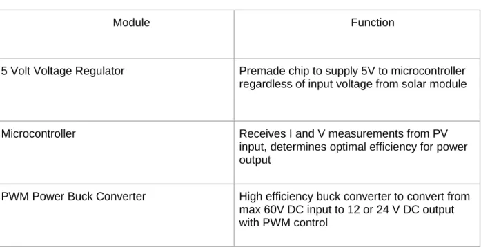
Table 3-3: Level 1 Description
Module Function
5 Volt Voltage Regulator Premade chip to supply 5V to microcontroller regardless of input voltage from solar module
Microcontroller Receives I and V measurements from PV
input, determines optimal efficiency for power output
Chapter 4. Design and Simulation Results
Solution Statement
To meet the specified design requirements, the 70V DC 327W power output from the PV module will be converted into 24 V DC for use by the water pump. This will be accomplished through a UART controlled DC-DC converter driven by an Arduino microcontroller. The Arduino will measure Vin and Iin to the DC-DC converter through use of a Hall sensor and resistor divider.
The output Voltage and current are reported to the Arduino through UART connection to the DC-DC converter. The UART connection is also used to control the output of the DC-DC converter. A Status LED will also be driven by the Arduino to indicate operation status. Not shown on the diagram is a liquid crystal display included in the DC-DC converter to indicate output voltage and current.
This solution makes use of Arduino control to help find the maximum power point by sampling different levels of power draw from the PV module and searching for the point of maximum power transfer to the pump (See Figure 2-1). The Arduino control will also allow for different operating modes to be pre-programmed to accommodate different sized water pumps, start up current control, and maximize power transfer.
Circuit Schematics
High voltage connections to the PV panel shall be made with weatherproof PV4 connectors, the industry standard for outdoor solar installations. The circuit shown inside the buck converter in Figure 4-2 is an approximation of the internal circuitry for design purposes [13].
While a stripped down buck converter could be used to reduce cost if this project was mass-produced, an off-the-shelf buck converter with UART communication is being used to expedite the design process. Conveniently, the Arduino will not have to provide a pulse width modulated switching signal, to the switch internal, to the buck converter in order to change output voltage. It will simply send the signal over UART to the buck converter unit to adjust voltage. Therefore, the logic of Figure 2-1 will be mostly followed, except instead of modifying the duty cycle, the output voltage will be changed directly. Testing will be performed to ensure that voltage and current measurements reported over UART by the buck converter are
accurate.
Sunpower E20-327
The PV Module used is a 327 Watt unit with 64.9VOC and 5.98 IMax [12].
Arduino Uno
The Arduino Uno Rev 3 features UART connection, digital and analog inputs, adn serial communications over USB to transfer data, perfect to gather information for this project [14]. DROK Buck Converter
The buck converter used is a DROK Buck converter module with 175V input and 0V-60V output. It can receive commands and communicate output data over UART to a
Hall Sensor
The hall sensor selected is a 20A range current sensor designed to work with an Arduino microcontroller [16].
Water Pump
Chapter 5. Hardware Tests and Results
Build Procedure
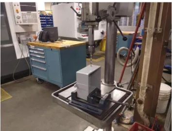
First, a NEMA-3 case was modified to allow for power cables to enter and exit through weatherproof fittings, and a toggle switch was drilled into the case.
Figure 5-1: Case Drilling
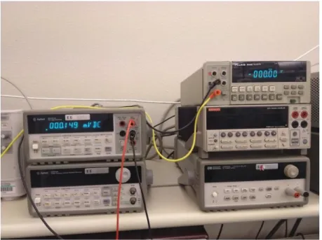
Lab testing was done using a dual source power supply in series to produce the 60V typical of an E20-327 solar module and resistive loads. Input current and voltage were taken from the dual source power supply. Output voltage and current were found using both digital multimeters and UART communication between the buck converter and Arduino.
Figure 5-4: Dual Source Power Supply
The following lab data was collected, P.S. refers to data collected from the dual power supply, MM refers to multimeter values. UART refers to values reported to the Arduino from the buck converter.
Table 5-1: Lab Data
Status P.S. VIn P.S. IIn MM VOut MM IOut UART VOut UART IOut
Off 60 .04 .115 0 0 0
On,R=20 60 1.08 24.32 1.171 24.30 1.16
On,R=30 60 .74 24.33 .786 24.29 .77
On,R=40 60 .59 24.33 .604 24.23 .59
On,R=50 60 .48 24.34 .481 24.21 .47
On, R=60 60 .42 24.32 .4015 24.22 .39
On,R=70 60 .38 24.32 .344 24.25 .33
On,R=80 60 .32 24.32 .302 24.29 .29
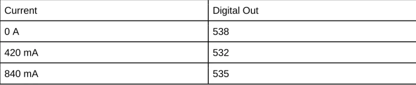
The two data points in Table 5-2 serve to demonstrate that the acquired Hall sensor does not have the necessary data precision for this project when driving an analog pin on the Arduino. Note: “Digital Out” represents the raw digital value reported by the Arduino on a scale of 0-1023 representing 0V through 5V.
The data obtained in the lab was analyzed in Excel to determine system efficiency and UART accuracy, shown in Table 5-3.
Table 5-3: Lab Data Analysis
Load
P.S.
VIn P.S. IIn P.S. PIn MM VOut MM IOut MM POut UART VOut UART IOut UART POut UART % error Efficien cy
Off 60 0.04 2.4 0.115 0 0 0 0 0 0.00% 0
R=20 60 1.08 64.8 24.32 1.171 28.478 24.3 1.16 28.188 1.02% 0.4394
R=30 60 0.74 44.4 24.33 0.786 19.123 24.29 0.77 18.703 2.19% 0.4307
R=40 60 0.59 35.4 24.33 0.604 14.695 24.23 0.59 14.295 2.71% 0.4151
R=50 60 0.48 28.8 24.34 0.481 11.707 24.21 0.47 11.378 2.80% 0.4065
R=60 60 0.42 25.2 24.32 0.4015 9.764 24.22 0.39 9.4458 3.26% 0.3874
R=70 60 0.38 22.8 24.32 0.344 8.366 24.25 0.33 8.0025 4.34% 0.3669
R=80 60 0.32 19.2 24.32 0.302 7.344 24.29 0.29 7.0441 4.09% 0.3825
The important takeaways from Table 5-3 are that the buck converter used in this project has a base efficiency of around 40% in lab conditions with higher efficiency at higher load. Also, the UART voltage and current reporting are within 5% error of what was measured by external multimeters, with a smaller error at higher loading. While it would have been ideal to perform lab tests with a higher power output, the resistive loads available had a maximum power rating of 20 Watts.
After lab testing, a resistor divider wired to an analog input on the Arduino with measured values of 50.4k and 675k was added to find the PV module’s input voltage to the buck converter.
Figure 5-6: Final Project Layout
To perform the outdoor testing, the solar panel was set up pointed directly towards the sun. The weather was not ideal. This can be seen in Figure 5-7, where the low angle of the sun was perpendicular to the high angle of the solar panel. The clouds blocking the sun can be seen in Figure 5-8.
Input
Switch
Input
UART
Figure 5-7: Outdoor Test Setup
The water pump acquired for this project was tested and functions perfectly when running at a fixed output voltage. However, it was replaced with a high power resistor for MPPT testing purposes, shown in Figure 5-9. A resistive load was chosen over the water pump to provide more consistent data. Furthermore, the largest pump affordable for this project was only 24V 22W, which could be easily powered by the equipment and would not push the PV module to its maximum power point. The resistor is rated at 1kw and contains different taps for different resistances. 4.6 Ohms was chosen on the basis that the buck converter had a nominal output rating of 0-60V and 12A. As the following calculations show, for a 327W PV module and 4.6 Ohm load, both these values are comfortably within operating limits.
Two forms of testing were performed. In phase one, output voltage values were
manually entered into the Arduino to test performance at those levels. In phase two, the control loop shown in Figure 2-1 was implemented and the device was allowed to find the MPPT on its own. The only difference is that output power was monitored by the Arduino instead of input power to find the MPPT. While not ideal, as shown in Table 5-2, the Hall sensor used is not accurate enough to precisely find the maximum power point. Further, the efficiency of the device was shown to be consistent enough in Table 5-3 to warrant this approach.
Table 5-4: Phase One Testing
V Desired Output Voltage Output Current Input Voltage (Raw)
5.00 4.85 1.09 63.382
10.00 9.24 2.09 62.679
15.00 13.65 3.09 61.623
20.00 18.08 4.10 59.302
25.00 9.20 2.09 8.653
11:30 am @ 63.1 Voc
V Desired Output Voltage Output Current Input Voltage (Raw)
10.00 10.24 2.33 63.312
12.00 12.26 2.78 62.819
14.00 14.26 3.23 61.975
16.00 16.24 3.69 61.272
18.00 18.26 4.14 60.216
20.00 20.23 4.59 58.176
22.00 9.03 2.04 8.442
24.00 9.06 2.05 8.582
12:00 pm @ 63.8 Voc
amp differences across the load. It is hypothesized that the reason for this is that the solar module was severely under-supplying the buck converter in this test, and that it self-limited to 13.7V, in-effect triggering an internal MPPT functionality. It is not certain why this did not trigger in previous tests, as the sharp dropoff experienced was repeatable. This suggests that the increased cloud coverage during this test led to this behavior. However, it is important to note that the purpose of MPPT technology is to extract the most power from a PV module during the given weather conditions, and while the data in Table 5-5 looks a bit unusual, it succeeds in this goal. Given the simple logic involved in the presented MPPT algorithm, had it been running during a run with better sunlight, such as the runs in Table 5-4, it would have fixated on the 20V operating point. It is interesting to note that while the changes noticed in Table 5-5 were small, the maximum power point still occurred near the 20V requested.
Repeated testing of the MPPT algorithm kept resulting in the 13.7V output cap, leading to the belief that there is some form of output limiting built into the buck converter that is
triggered at especially low input power levels, while the runs before were not capped due to the brighter sun and were therefore able to push past the maximum power point.
Table 5-5: Phase Two MPP Testing
V Desired Output Voltage Output Current Input Voltage (Raw)
12.00 12.27 2.77 61.975
13.00 13.25 3.00 61.412
14.00 13.69 3.10 61.483
15.00 13.69 3.10 61.834
16.00 13.70 3.10 61.412
17.00 13.70 3.10 61.342
18.00 13.70 3.10 59.372
20.00 13.70 3.10 60.005
21.00 13.71 3.09 59.090
20.00 13.70 3.10 61.694
19.00 13.70 3.10 61.764
18.00 13.70 3.09 61.623
19.00 13.70 3.10 61.623
Chapter 6. Conclusion
MPPT through a microcontroller driven buck controller is an effective way to find the optimal current draw from a solar module and maintain that level of operation under changing weather conditions. However, the efficiency of the buck converter selected for this project was sub-par, averaging around 40%. This means that any gains from the MPPT technology were lost to how lossy the circuitry was. However, this project was successful in showing that the use of a microcontroller can optimize the power output of a given buck converter when paired with a MPPT algorithm and a PV module.
This project is more than capable of driving a variety of water pumps, and could easily be modified into a charge controller for a battery through coding changes alone. This is an excellent level of versatility and usability from consumer grade equipment ordered online. While tested with a computer connected for data acquisition, the device functions autonomously, finding the maximum power point without any intervention. The solar panel powers up the buck converter, which turns on the Arduino, which in turn activates the output and search algorithm as soon as the switch is flipped.
References
[1]. A. Azoulay, "The United Nations world water development report 2018: nature-based solutions for water ", Unesdoc.unesco.org, 2019. [Online]. Available:
https://unesdoc.unesco.org/ark:/48223/pf0000261424. [Accessed: 08- Mar- 2019]. [2]. A. Louwen, "Re-assessment of net energy production and greenhouse gas emissions
avoidance after 40 years of photovoltaics development ", 2019. [Online]. Available: https://www.nature.com/articles/ncomms13728. [Accessed: 08- Mar- 2019].
[3]. E. Leonard, "Do Solar Modules Ever Repay Their Energy Debt? ", Artisan Electric, 2019. [Online]. Available: https://artisanelectricinc.com/solar-modules-ever-repay-energy-debt/. [Accessed: 08- Mar- 2019].
[4]. "Net Farm Income Projected to Drop to 12-Year Low ", Fb.org, 2019. [Online]. Available: https://www.fb.org/market-intel/net-farm-income-projected-to-drop-to-12-year-low. [Accessed: 08- Mar- 2019].
[5]. “Irrigation Water Use,” USDA ERS - Food Environment Atlas. [Online]. Available:
https://www.ers.usda.gov/topics/farm-practices-management/irrigation-water-use/. [Accessed: 28-Feb-2019].
[6]. D. Choudhary, "DC-DC Buck-Converter for MPPT of PV System ", Citeseerx.ist.psu.edu, 2019. [Online]. Available:
http://citeseerx.ist.psu.edu/viewdoc/download?doi=10.1.1.641.1695 rep=rep1 type=pdf. [Accessed: 26- Apr- 2019].
[7]. P. Rao, "Maximum Power from PV Arrays Using a Fixed Configuration Under Different Shading Conditions - IEEE Journals Magazine ", Ieeexplore.ieee.org, 2019. [Online]. Available: https://ieeexplore.ieee.org/document/6730676. [Accessed: 04- Feb-2019]. [8]. A. Oi, “DESIGN AND SIMULATION OF PHOTOVOLTAIC WATER PUMPING SYSTEM,”
Cal Poly Digital Commons, Sep-2005. [Online]. Available:
https://courseware.ee.calpoly.edu/~jharris/super_project/ao_thesis.pdf [Accessed: 02-Feb-2019].
[9]. “Competing for Clean Water Has Led to a Crisis,” National Geographic, 27-Jan-2017. [Online]. Available:
https://www.nationalgeographic.com/environment/freshwater/freshwater-crisis/. [Accessed: 28-Feb-2019].
[10]. "NEMA Enclosure Types ", Nema.org, 2019. [Online]. Available:
[11]. M. Holt, "Navigating the NEC's Rules for Bodies of Water ", Electrical Construction Maintenance (EC M) Magazine, 2019. [Online]. Available:https://www.ecmweb.com/code-basics/navigating-necs-rules-bodies-water. [Accessed:08- Mar- 2019].
[12]. Sunpower E-Series Residential Solar Panels | E20-327, Us.sunpower.com, 2019. [Online]. Available:https://us.sunpower.com/sites/default/files/media-library/data-sheets/ds-e20-series-327-residential-solar-panels.pdf. [Accessed: 04- Feb- 2019].
[13]. Taufik EE410 Power Electronics I - Lecture Note Cal Poly State University, San Luis Obispo, 2004
[14]. “Arduino Uno Rev3,” Arduino Uno Rev3 | Arduino Official Store. [Online]. Available: https://store.arduino.cc/usa/arduino-uno-rev3. [Accessed: 13-Dec-2019].
[15]. “DROK Buck Converter,” Amazon, 2011. [Online]. Available:
https://www.amazon.com/gp/product/B071LGTTRN/ref=ppx_yo_dt_b_asin_title_o04_s01? ie=UTF8&psc=1. [Accessed: 13-Dec-2019].
[16]. “Gikfun 20A Range Current Sensor,” Amazon, 2011. [Online]. Available:
https://www.amazon.com/gp/product/B00RBHOLUU/ref=ppx_yo_dt_b_asin_title_o04_s00 ?ie=UTF8&psc=1. [Accessed: 13-Dec-2019].
[17]. “ZAOJIAO DC 24V Brushless Water Pump,” Amazon, 2011. [Online]. Available:
Appendix A
Analysis of Senior Project Design Project Title: PV Water Pump Controller Students Name: Jacob Lamkin
Students Signature:
Jacob Lamkin
1. Summary of Functional Requirements
The PV Water Pump Controller converts DC electric power from a solar module into DC power for a water pump. The system measures input voltage and output current levels,
adjusting the output to obtain optimal operating efficiency at any power input level. 2. Primary Constraints
Constraints surrounding this project include the need for high efficiency and low cost. Additionally, reliability and simplicity are necessary both wide scale accessibility. This lead to the decision to not include battery storage in the design, which would add expense, weight, and installation complexity and dangers, as well as decreased reliability.
3. Economic
The PV Water Pump Controller will positively impact the people around it. Providing automated pumped and running water frees up people’s time and energy. This could manifest as a farmer being able to care for more crops, or an impoverished person being able to stay healthy with fresh water. From an industry standpoint, this project promotes the solar and power electronics industries, both high paying technical fields with good jobs. The earth’s natural capital comes into play when considering that although manufacturing takes energy and creates pollution, long term impacts of a solar installation are far less than that of a gas generator.
4. If Manufactured on a Commercial Basis
estimated $500,000 profit per year. The user replacement cost should remain below $100 per year for the end customer with a $300 price point and minimum 3 years of function.
5. Environmental
The PV Powered Pump Controller will positively impact the environment through removing the need for a gas generator to power an electric water pump. The power produced will not create any environmental strain, and the environmental impact of manufacturing the solar panel and pump controller are offset by the manufacturing cost that would be necessary to manufacture a generator. Additionally, using running water for agricultural purposes will
increase the earth’s biomass by allowing more plants to grow. 6. Manufacturability
Issues associated with manufacturing revolve around a process consistent enough to guarantee 3 years of uninterrupted function. Due to target markets in rural and somewhat inaccessible locations, a warranty will be ineffective at helping the customer, as the time
required to receive a replacement could be detrimental. Since this product could be relied upon for a primary food or water source, consistent function through quality manufacturing is required.
7. Sustainability
The PV Water Pump Controller supports the sustainable use of energy and water. Gasoline will not be used to power a generator for an electrical pump, and the water will can be used for sustainable farming. Overall, the PV Water Pump Controller is a sustainable system for delivering water.
However, any malfunction of the system will jeopardize a water source. Replacing a hand pump with a PV system exposes vulnerable people to a water outage due to lack of sun or technical malfunction. Any situation when harm is caused due to a lack of water in a situation where a hand pump would have sufficed is an ethical responsibility of the seller. However, existing hand pumps may be left installed in parallel with this system to mitigate these concerns and ease the ethical responsibility of the manufacturer.
The IEEE ethics framework requires disclosing any factors that might endanger the public and any conflicts of interest. These have been met through the above analysis of the impacts of this project. Honest estimates, rejection of bribes, acceptance of criticism,and assistance to colleagues fall under personal responsibilities pertaining to designing the system, not the system itself.
A utilitarian approach to the PV Water Pump Controller would determine it to be very ethical. While not a perfect solution for all use cases, cheap, dependable, scalable systems are designed to help as many people as possible. This fulfills the definition of utilitarian ethics perfectly.
9. Health and Safety
This system interacts with drinking water, so while the pump controller itself does not need to be good grade, the pump itself should be. The pump controller must remain electrically isolated from both the water and the case for end user safety. The combination of high power levels and water requires caution in design to remain safe over an extended period of time.
10. Social and Political
Water is a life necessity, and therefore political forces could feasibly be involved in the purchasing and implementation of the PV Water Pump Controller system. Distribution of this system to aid low income farmers and communities creates an inherent question of who gets it and who doesn't.
Appendix B
#include "Arduino.h" void setup()
{
Serial.begin(4800); //buck baud rate
Serial.print("Initialising PSU...");
pinMode(7, INPUT); //Soft Switch Input pinMode(A0, INPUT); //hall
pinMode(A1, INPUT); //vin through r dividor delay(5000);
}
int Rx;
int hallbaseline = 519; // constant for 0 value int voltage; String voltageSTR; String currentSTR; String outputSTR; int fakeval; int outputvoltage; int outputcurrent; int inputvoltage; int inputcurrent; int switchpos; int v = 600; int i = 200;
void loop() { while (v<2500){ SetVoltage(v); delay(1000); Cycle(); v +=200; }
v = 600;
while (i<1100){ SetCurrent(i); delay(1000); Cycle(); i +=100; }
i = 200;
}
void SwitchCheck () {
int switchpos = digitalRead(7); if (switchpos==1){
SetPower(1); }
else{
} } void Cycle(){ SwitchCheck();
// SetVoltage(2400); // SetVoltage(v); delay(200);
fakeval = CheckVoltage(); delay(500);
outputvoltage = CheckVoltage(); delay(500);
fakeval = CheckCurrent(); delay(500);
outputcurrent = CheckCurrent(); delay(500);
inputcurrent = CheckCurrentHall(); inputvoltage = analogRead(1);
// inputvoltage = CheckVoltageIn();
PrintData(); }
void PrintData(){
Serial.println("v desired e-2 is "); Serial.println(v);
Serial.println("i desired e-2 is "); Serial.println(i);
Serial.println("output voltage e-2 is "); Serial.println(outputvoltage);
Serial.println("input voltage e-2 (fixed) is "); Serial.println(inputvoltage);
Serial.println("input current (broken) is "); Serial.println(inputcurrent);
Serial.println("Input Power is");
Serial.println(inputvoltage*inputcurrent);
Serial.println(""); */
}
void SetPower (int power) {
if (power==1){ Serial.println("awo1"); } else{ Serial.println("awo0"); } }
void SetVoltage (int voltage) {
if (voltage < 10){
voltageSTR = "000"+String(voltage); }
else if (voltage < 100){
voltageSTR = "00"+String(voltage); }
else if (voltage < 1000){
voltageSTR = "0"+String(voltage); }
else {
voltageSTR = String(voltage); }
outputSTR = "awu"+voltageSTR; Serial.println(outputSTR);
}
void SetCurrent (int current) {
if (current < 10){
currentSTR = "000"+String(current); }
currentSTR = "00"+String(current); }
else if (current < 1000){
currentSTR = "0"+String(current); }
else {
currentSTR = String(current); }
outputSTR = "awi"+currentSTR; Serial.println(outputSTR);
}
int CheckVoltage () { Serial.println("aru"); Serial.println("aru"); String storedData = ""; String storedNum = "";
while(!Serial.available() ){ }
if( Serial.available() ){ // if new data is coming from the HW Serial while(Serial.available()) // reading data into char array {
char inChar = Serial.read(); storedData += inChar;
// This makes a string named storedData }
}
storedData.remove(0,3); return ((storedData).toInt()); }
int CheckCurrent () { Serial.println("ari"); Serial.println("ari"); String storedData = ""; String storedNum = ""; while(!Serial.available() ){ }
if( Serial.available() ){ // if new data is coming from the HW Serial while(Serial.available()) // reading data into char array {
Appendix C
#include "Arduino.h" void setup() { Serial.begin(4800); Serial.print("Initialising PSU...");pinMode(7, INPUT); //Soft Switch Input pinMode(A0, INPUT); //hall
pinMode(A1, INPUT); //vin through r dividor delay(5000);
}
int Rx;
int hallbaseline = 519; int voltage; String voltageSTR; String currentSTR; String outputSTR; int fakeval; int outputvoltage; int outputcurrent; int inputvoltage; int inputcurrent; int switchpos; int v = 1200; int i = 1000; int powercheck; int newpowercheck; int incriment=1; int startup=1; ///////// void loop() { if (startup==1){ SetCurrent(i); startup=0; } SetVoltage(v); delay(3000); Cycle();
//this part of the code increments and decrements the voltage output to find the MPPT if (incriment==1){ if (newpowercheck<powercheck){ incriment=0; v -=100; return; } v +=100; } if (incriment==0){ if (newpowercheck<powercheck){ incriment=1; v +=100; return; } v -=100; } } ///////////////////////////
void SwitchCheck () {
fakeval = CheckVoltage();
//must be called twice to get correct value delay(500);
outputvoltage = CheckVoltage(); delay(500);
fakeval = CheckCurrent(); delay(500);
outputcurrent = CheckCurrent(); delay(500);
inputcurrent = CheckCurrentHall(); inputvoltage = analogRead(1);
PrintData(); }
void PrintData(){
Serial.println("v desired e-2 is "); Serial.println(v);
Serial.println("i desired e-2 is "); Serial.println(i);
Serial.println("output voltage e-2 is "); Serial.println(outputvoltage);
Serial.println("output current e-2 is "); Serial.println(outputcurrent);
// Serial.println("Output Power (uw) is");
// Serial.println(outputvoltage*outputcurrent*100);
Serial.println("input current (raw) is "); Serial.println(inputcurrent);
Serial.println("input voltage (raw) is "); Serial.println(inputvoltage);
/*
Serial.println("input voltage e-2 (fixed) is "); Serial.println(inputvoltage);
Serial.println("Input Power is"); Serial.println(inputvoltage*inputcurrent); Serial.println(""); */ }
void SetPower (int power) {
if (power==1){ Serial.println("awo1"); } else{ Serial.println("awo0"); } }
void SetVoltage (int voltage) {
if (voltage < 10){
voltageSTR = "000"+String(voltage); }
else if (voltage < 100){
voltageSTR = "00"+String(voltage); }
else if (voltage < 1000){
voltageSTR = "0"+String(voltage); }
else {
voltageSTR = String(voltage); }
outputSTR = "awu"+voltageSTR; Serial.println(outputSTR);
else if (current < 1000){
currentSTR = "0"+String(current); }
else {
currentSTR = String(current); }
outputSTR = "awi"+currentSTR; Serial.println(outputSTR);
}
int CheckVoltage () {
Serial.println("aru"); Serial.println("aru"); String storedData = ""; String storedNum = "";
while(!Serial.available() ){ }
if( Serial.available() ){ // if new data is coming from the HW Serial while(Serial.available()) // reading data into char array {
char inChar = Serial.read(); storedData += inChar;
// This makes a string named storedData } } storedData.remove(0,3); return ((storedData).toInt()); }
int CheckCurrent () {
Serial.println("ari"); Serial.println("ari"); String storedData = ""; String storedNum = "";
while(!Serial.available() ){ }
if( Serial.available() ){ // if new data is coming from the HW Serial while(Serial.available()) // reading data into char array {
// This makes a string named storedData }
}
storedData.remove(0,3); return ((storedData).toInt()); }
int CheckCurrentHall () {
![Figure 1-1: Theoretical MPPT Chart [6].](https://thumb-us.123doks.com/thumbv2/123dok_us/8223737.2180246/8.918.260.649.110.436/figure-theoretical-mppt-chart.webp)
![Figure 2-1: MPPT Control Loop Logic [6]](https://thumb-us.123doks.com/thumbv2/123dok_us/8223737.2180246/11.918.173.769.109.891/figure-mppt-control-loop-logic.webp)