Coordination of Regenerative Relays and Direct
Users in Wireless Cellular Networks
Chan Dai Truyen Thai and Petar Popovski
Department of Electronic Systems, Aalborg University
Email:
{
ttc, [email protected]
}
Abstract—The area of wireless cooperation/relaying has re-cently been significantly enriched by the ideas of wireless network coding (NC), which bring substantial gains in spectral efficiency. These gains have mainly been demonstrated in scenarios with two–way relaying. Inspired by the ideas of wireless NC, recently we have proposed techniques for coordinated direct/relay (CDR) transmissions. These techniques embrace the interference among the communication flows to/from direct and relayed users, leveraging on the fact that the interference can be subsequently canceled. Hence, by allowing simultaneous transmissions, spectral efficiency is increased. In our prior work, we have considered CDR with non-regenerative relay that uses Amplify-and-Forward (AF). In this paper we consider the case of regenerative Decode– and–Forward (DF) relay. This refers also to joint decoding of the interfering flows received over a multiple-access channel. Our analysis shows that the assumption of regenerative relaying brings new parametrization of the CDR schemes, such that the the transmission times used by each node are subject to optimization. We show how these parameters should be chosen if the sum–rate needs to be optimized. Our results confirm the high gains in spectral efficiency over the reference schemes.
Index Terms—Cooperative communications, relaying, analog network coding, interference cancelation, a priori information.
I. INTRODUCTION
Recently there have been extensive studies on cooperative, relay–based transmission schemes for extending cellular cover-age or increasing diversity. Several basic relaying transmission techniques have been introduced, such as amplify-and-forward (AF) [3], decode-and-forward (DF) [4] and compress-and-forward (CF) [5]. These transmission techniques have been applied in one-, two- or multi-way relaying scenarios.
In particular, two–way relaying scenarios [1], [2], [6] have attracted a lot of attention, since it has been demonstrated that in these scenarios one can apply techniques based on NC in order to obtain a significant throughput gain. There are two basic principles used in designing throughput–efficient schemes with wireless NC (1) aggregation of communication flows- NC operates by having the flows sent/processed jointly; (2) intentional cancellable interference: flows are allowed to interfere over the wireless channel, knowing a priorithat the interference can be cancelled by the destination.
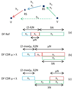
Using these insights, in [11] we have proposed schemes, depicted on Figs. 1 and 2 for traffic scenarios that are more general than the usual two–way relaying. These schemes are termed coordinated direct/relay (CDR) transmissions. In the scheme on Fig. 1, termedS1, U receives downlink traffic from the BS, while V sends uplink traffic to the BS. For the scheme
S1 (Fig. 2, these traffic patterns are inverted), in the first step the BS transmits to the relay RS. In the second step, RS transmits to U and simultaneously V transmits to the BS. The reception of V’s signal at BS is interfered by the transmission of RS; however, since BS knows the signal of RSa priori, it can cancel it and get a “clean” message from V. Enabling such simultaneous transmissions improves the spectral efficiency. In schemeS2, in the first step BS sends to V and simultaneously U sends to RS, such that RS receives interference of these two signals, such as in analog NC for two–way relaying. But, unlike two–way relaying, the signal sent by RS in the second step need only be decoded at BS, but not at U. This makes the link RS-U irrelevant and, as we will see later, deflecting the traffic to go BS-V instead of BS-RS-U, and combining it with the traffic U-RS-BS, can give advantages in the sum–rate.
In [11] we have considered RS that uses Amplify-and-Forward (AF). In this paper we consider schemes in which RS decodes the signals that it needs to relay. We will see that such an assumption significantly complicates the analysis compared to the AF operation, since the choice of the duration of different phases in the schemes S1, S2 is subject to optimization. In this paper, the optimization objective is the sum–rate for each of the respective schemes. In addition, we discuss the relation to the two–way relaying schemes with decoding at the relay and show the rate advantages brought by the generalized traffic patterns.
This paper is organized as follows. Section II describes the system model. The reference and CDR schemes are described and analyzed in Section III. Section IV presents the numerical results and the relation to the two–way relaying. Section V concludes the paper.
II. SYSTEMMODEL
µN x1 h2 BS
RS
V U
h3
x2 h4
h1
x1 x2 DF Ref
λN x1
(2-λ)N
(2-max(µ, λ))N
(a)
µN
λN x1 x1
x2
µN λN x1
x2 DF CDR µ > λ
(2-max(µ, λ))N
(b)
(c) x1
µN
DF CDR µ < λ
(2-max(µ, λ))N x1
x2
Fig. 1. Time slots in Reference (a) and CDRS1Schemes (b, c).
notation:x4is the packet sent from BS to V, while the packets that BS needs to receive arex3 from U andx2 from V. Note that the example on Fig. 1 does not show traffic patterns that involvex3 andx4, but they are used on Fig. 2.
The direct channel BS–U is assumed weak and U gets the information from BS only through the decoded/forwarded signal from RS. If the reception ofxis additionally interfered byw, then the received signal isy=hix+hjw+z. Denoting the capacity function asC(γ) = log2(1 +γ), we can write the capacity of such a transmission as Ci−j = C
|h
i|2
|hj|2+σ2
= C gi
gj+1
with gi = |hi|
2
σ2 . In case there is no interfering signal the capacity isCi= log2(1 +gi). If the receiver jointly decodesxandw, the maximal sum rate for these two signals is Cij = log2(1 +gi+gj). It is straightforward to see that
Cij =Cji, Cij =Cj+Ci−j.
In each scheme, the total time length is 2N symbols. RiU
and RiV, i ∈ {E, S1, S2} are maximal rates for U and V respectively in schemei.E denotes the reference scheme, all schemes will be described in the next part. The sum–rate is therefore estimated as Ri
sum=RiU +R i
V =
1 2N(D
i
U+D
i V), where Di
U, D i
V represent the correspondent number of bits. The transmission for the direct user has a duration of λN
symbols. In the following part, we analyze the choice of λ
with respect to the optimization of the sum–rate.
III. REFERENCE ANDCDR SCHEMES
A. Reference Scheme
BS first transmits x1 to RS, RS decodes x1 and transmits it to U (see Fig. 1 (a)). V after that transmitsx2to BS. Since the V–BS transmission’s length is pre-defined asλN symbols and all transmissions are performed separately, the total time length for U is therefore (2−λ)N. We denote the number of symbols in the RS–U transmission as µN. The maximal data sent through the BS–RS, RS–U and V–BS transmissions
are respectively DE
U1 = (2−λ−µ)N C1, D
E
U2 = µN C2, DE
V = λN C3. The total data transmitted for two users is
DE
sum = min(DUE1, D
E U2) +D
E
V. Since D E
V does not depend onµ,DUE1 is a decreasing function andDEU2 is an increasing function of µ, in order to get maximal DsumE , µ is selected such that DEU1 = DUE2. Solving this equation we have the optimal µ = µE
opt =
(2−λ)C1
C1+C2 . The data for U and V are respectivelyDE
U = (2−λ)N C1C2
C1+C2, D
E
V =λN C3.The sum– rate isRE
sum=
(2−λ)C1C2 2(C1+C2) +
λN C3 2 .
B. CDR Scheme 1
BS first transmits x1 to RS (see Fig. 1 (b, c)). After that RS decodes x1 and transmits it to U. In the meantime, V transmits x2 to BS. The length of the transmission for the direct user, which is the V–BS transmission here, is pre-defined as λN symbols. Denote the number of symbols in the RS– U transmission as µN. Since BS and RS cannot transmit and receive at the same time, the BS–RS transmission cannot be performed simultaneously with any other transmission. Because the RS–U and V–BS transmissions do not completely coincide, the length of the BS–RS transmission is thus deter-mined as (2−max(µ, λ))N. In the following, we estimate the optimal value of µ for a pre-defined value of λ. Since BS knows x1 thus BS cancels the contribution of x1 in the received signal. The total data sent through the BS–RS, RS–U and V–BS transmissions are respectively
DS1
U1 = (2−max(µ, λ))N C1 DS1
U2 = min(µ, λ)N C2−4+ (µ−min(µ, λ))N C2 DS1
V =λN C3.
(1)
The total data for two users is therefore DS1
sum =
min(DS1
U1, D
S1
U2) +D
S1
V . Similar to Reference Scheme, since
DS1
V does not depend onµ,D S1
U1 is a decreasing function and DS1
U2 is an increasing function of µ, in order to get maximal DS1
sum, µ is selected such that D
S1
U1 = D
S1
U2. We estimate optimalµand sum–rate by considering two following cases:
• If µ ≥ λ: DS1
U1 = (2− µ)N C1, D
S1
U2 = λN C2−4 + (µ−λ)N C2. We set DSU11 = D
S1
U2 and get µ = µ
S1 opt = 2C1+λ(C2−C2−4)
C1+C2 . Condition µ ≥ λ is satisfied when λ ≥ λS1
o =C1+2CC12−4.
RS1
sum, µ≥λ=
minDS1
U1, D
S1
U2
+DS1
V
2N
= [(2−λ)C2+λC2−4]C1 2(C1+C2)
+λC3
2 . (2)
• If µ < λ: DS1
U1 = (2−λ)N C1, D
S1
U2 =µN C2−4. We set DS1
U1 = D
S1
U2 and get µ = µ
S1 opt =
(2−λ)C1
C2−4 . Similar to the previous case, condition µ < λis satisfied whenλ < λS1
o .
RS1
sum, µ<λ =
(2−λ)C1+λC3
2 . (3)
Solving RS1
sum, µ≥λ ≥ R S1
sum, µ<λ, we can get λ ≥ λ S1
o . Thus in summary, we have
RS1 sum=
(
RS1
sum, µ≥λ if λ≥λ S1
o
RS1
sum, µ<λ if λ < λ S1
o .
BS
RS
x4
x3 x3
λN
(2- max(x, λ))N V U
µN x3
x3 x4
(2- max(x, λ))N DF CDR x > λ
x3 x3
λN
(2- max(x, λ))N µN
x4 x4
DF CDR x < λ
Fig. 2. Time slots in CDR SchemeS2.
C. CDR Scheme 2
First U transmitsx3to RS inµNsymbols and BS transmits
x4 in λN symbols simultaneously (see Fig. 2). It is not necessary that the U–RS and V–BS transmissions completely coincide. During the first min(µ, λ)N symbols, both U and BS transmit. Denote the rates from U and from BS in this period as RU andRV respectively. RU andRV are selected such that RS can decode both
RU ≤C2, RV ≤C1, RU+RV ≤C12 (5) and V can decode x4 treatingx3 as noise
RV ≤C3−4. (6)
After that, if µ > λ, BS stops transmitting and U turns to transmit with rate C2, the maximum rate over the U–RS channel achieved with no interference. Conversely, if µ < λ, U stops transmitting and BS turns to transmit with rate C3, the maximum rate over the BS–V channel achieved with no interference. Since BS and RS cannot transmit and receive at the same time, the RS–BS transmission cannot be performed simultaneously with any other transmission, it starts only after the firstmax(µ, λ)N symbols are finished. RS thus transmits
x3 to BS in(2−max(µ, λ))N symbols.
The data transmitted in U–RS, RS–BS and BS–V transmis-sions are respectively
DS2
U1 = min(µ, λ)RUN+ (µ−min(µ, λ))C2N DS2
U2 = (2−max(µ, λ))C1N DS2
V = min(µ, λ)RVN+ (λ−min(µ, λ))C3N. (7)
The total data transmitted DS2
sum = min(D
S2
U1, D
S2
U2) +D
S2
V . With a pre-defined λ, we derive µ, RU, RV which give the highestDS2
sum. Denote the set containing(RU, RV)points sat-isfying the conditions (5) and (6) areA1 andA2 respectively.
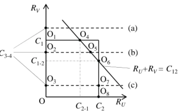
A1 here is pentagonal OO1O4O6O8 in Fig. 3 and A2 is all the area below the line RV =C3−4. The optimizing problem can be summarized as
DS2
sum−max= max
(RU, RV)∈A1∩A2 0≤µ≤2
DS2
sum. (8)
There are three different rate regionsA1∩A2 corresponding to three cases in Fig. 3 (a) OO1O4O6O8 if C3−4 ≥C1, (b)
O8
O7
(a)
R RV
C1
RU+RV = C12
(b)
(c)
O
C1-2 C3-4
O1
O2
O3
O4
O5
O6
RU
C2
O
C2-1
Fig. 3. Rate regions corresponding to different cases of channels.
OO2O5O6O8 if C1−2 ≤ C3−4 < C1, and (c) OO3O7O8 if 0< C3−4< C1−2.
Because DS2
sum is an increasing function of RU and RV, it is straightforward to see that it achieves its maximum at a point in the line segment O4O6 because from this point we cannot move further to the right or higher. We therefore consider only points (RU, RV) in this line segment. These points satisfies the equation RU +RV = C12. Hence RV can be written in terms of RU as RV = C12 −RU with
RU varying correspondingly in one of the three intervals
[C2−1, C2],[C12−C3−4, C2],[C2, C2]. By substitutingRV to
DS2
sum and re-arranging, we have
DS2
sum= min(D
S2
U1, D
S2
U2) +D
S2
V
= min[min(µ, λ)N(RU −C2) +µN C2, (2−max(µ, λ))N C1]
+ min(µ, λ)N(C12−C3−RU) +λN C3. (9) Maximizing this function for general channels is cumbersome because we have to consider several cases therefore we make some assumptions as follow which are close to a practical case
C1−2< C3−4< C1 (case (b) in Fig. 3) andC12> C3. This is because RS and BS are designed so as the channel between them (γ1) is large and typically larger than the channel between V and BS (γ3). Moreover, the channel between two mobile users (γ4) is small and typically smaller than the channel between U and RS (γ2). In summary, we need to find
DS2
sum−max= max
RU∈[C12−C3−4, C2]
µ∈[0,2]
DS2
sum. (10)
Because DS2
sum is a linear function of RU and µ, all of its second derivatives are 0. Its maxima can be achieved at points where its first derivatives do not exist or at boundary points. First, DS2
sum
0
µ does not exist at points where D S2
U1 =D
S2
U2. Second, because there is function min(µ, λ) inside function
DS2
sum, at points whereµ=λ, its first derivatives also do not exist. We consider three cases:
• Ifµ > λ, the equation DS2
U1 =D
S2
U2 is equivalent to
λRUN+(µ−λ)C2N= (2−µ)C1N, µ=
2C1+λC2−λRU
C1+C2
.
(11) We have
DS2 sum=λN
C1
C1+C2
−1
RU+
(2−λ)N C1C2
C1+C2
+λN C12
0 0.5 1 1.5 2 0
0.5 1 1.5 2 2.5 3 3.5 4 4.5
λ
R
a
te
(
b
p
s
)
RDF-E
U
RDF-EV RDF-Esum RDF-S1
U
RDF-S1 V
RDF-S1 sum
RAF-S1 sum
µoptDF-S 1
µoptDF-E
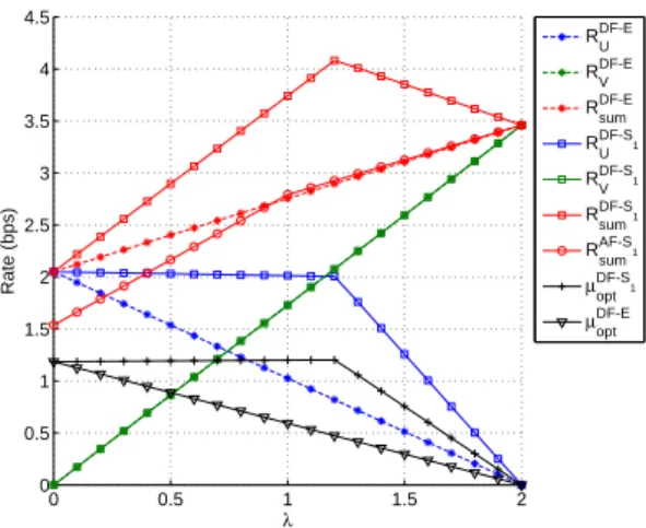
Fig. 4. Rates and optimalµin DF Reference, CDR Scheme 1 and AF CDR Scheme 1. Note thatµhas a different unit.
It is a decreasing function of RU since C1C+1C2 < 1. We therefore consider the lower boundary point RU = C12−
C3−4. Substituting it to (11) and noting C12 = C1−2+C2,
µ=µS2 opt =
2C1−λC1−2+λC3−4
C1+C2 .In order to haveµ > λ,λ < λS2
o =
2C1
C12−C3−4+C1.When the condition above is satisfied,
DS2
sum, µ≥λ=
2C2+λ(C1−2−C3−4)
C1+C2
N C1+λN C3−4. (13)
• Ifµ < λ, the equationDS2
U1=D
S2
U2 is equivalent to
µN RU = (2−λ)C1N and µ=µSopt2 =
(2−λ)C1
RU
(14)
We have DS2
sum =
(2−λ)N C1(C12−C3)
RU +λN C3. It is also a decreasing function since C12 > C3 as assumed above. We therefore consider the lower boundary point RU = C12−
C3−4. Substituting it to (14), we haveµ=
(2−λ)C1
C12−C3−4.In order to haveµ < λ, it has to satisfiesλ > λS2
o
DS2
sum, µ<λ=(2−λ)N C1+
(2−λ)N C1(C12−C3)
C12−C3−4
+λN C3−(2−λ)N C1. (15)
•If µ=λ,DS2
sum does not depend onRU
DS2
sum, µ=λ= min(λRU,(2−λ)C1) +λ(C12−RU)
= min(λC12,(2−λ)C1+λC3−4). (16)
Finally, µ is chosen as the value making the total data the
highest and RS2 sum=
maxDS2 sum, µ≥λ,D
S2
sum, µ<λ,D
S2
sum, µ=λ
2N .
IV. NUMERICALRESULTS
In all simulations below, the channels are fixed [g1 g2 g3 g4] = [15 10 10 − 10]dB unless stated otherwise. Fig. 4 shows the sum–rate and rates for U and V in CDR and Reference Scheme 1 with respect to λ. While Reference Scheme’s sum–rate REsum is a linearly increasing function with respect to λ, CDR Scheme 1’s sum–rate RS1
sum achieves a maximum at a certain value of λ. In Reference Scheme’s case, it is straightforward since when λ increases
0 0.5 1 1.5 2
0 0.5 1 1.5 2 2.5 3 3.5 4
λ
R
a
te
(
b
p
s
)
RDF-S2
U RDF-S2
V RDF-S2
sum RAF-S2
sum µoptDF-S
2
Fig. 5. Rates and optimalµin DF and AF CDR Scheme 2. Note thatµhas a different unit.
µN
h2 BS
U h1
x1 x2
λN x3
(4-2λ)N
x2
x1 x3
λN
Fig. 6. Reference Scheme in the scenario with two–way traffic.
data transmitted for V increases and data transmitted for U decreases but the former is with a higher speed due to a direct transmission compared to a two–hop transmission. Whenλ= 0, the whole time is used for U and µis fixed at a value to balance the data transmitted of two hops. When λ
increases, the time for U in Reference Scheme is shortened accordingly. However in CDR Scheme 1, the time for U is not changed with a slightly different balance point (µ) because the V’s transmission slightly affects the U’s transmission. In the meantime, transmitted data for V increases therefore the sum–rate increases with a high speed. When λ reaches the balance point of U’s DF transmissions and continues to increases, the time for RS–U has to decreases accordingly to balance with a small data transmitted in BS–RS transmission. With a small inter–user channel, the interference from a user to the other is negligible, CDR Scheme 2’s rates and sum–rate has a quite similar slopes as seen in Fig. 5. In the two figures, AF CDR schemes S1, S2 are worse than their DF CDR respective schemes. For AF CDR schemes, λ is re-defined as∈[0, 2]instead of[−1, 1]as in [12].
In the part above, we consider a scenario in which U or V has a downlink or uplink only. In the following part, we assume that both have a downlink and an uplink. All the assumptions regarding the channels and packets are the same. The time length for the whole scheme is now 4N symbols long.
-20 -15 -10 -5 0 5 10 1.5
2 2.5 3 3.5 4
Inter--user channel (dB)
R
a
te
(
b
p
s
)
R sum S
1
R sum S
2
RsumS1,2
R sum E, NC
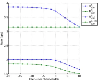
Fig. 7. Rates for CDR Scheme 1,2 and Reference Scheme combined with Two–way Relay Network Coding.
same. Denote µN as the number of symbols in BS–RS phase and D2w as the data transmitted in each phase. Because the maximal rates in BS–RS, U–RS and broadcast phases are
C1, C2,min(C1, C2) respectively, the number of symbols in the corresponding phases are D2W
C1 ,
D2W
C2 ,
D2w
min(C1,C2). We have D2W
C1
+D2W
C2
+ D2W
min(C1, C2)
= (4−2λ)N. (17)
We can estimateD2W and the number of symbols in BS–RS, U–RS and broadcast phases are
µEopt−2W =D2W
C1
= (4−2λ)N
1 + C1
C2 +
C1 min(C1,C2)
. (18)
and C1
C2µ
E−2W
opt ,
C1 min(C1,C2)µ
E−2W
opt . The rate for the whole scheme is thus
REsum−2W =
2D2W+ 2N C3
4N =
µEopt−2WC1+C3
2 . (19)
In CDR Scheme, the scheme for two–way traffic is simply a combination between CDR Scheme 1 and CDR Scheme 2 thus the rate is RS1,2
sum = R
S1
sum+R
S2
sum
2 .
Varying the inter-user channel and keeping the other chan-nels, we compare the rates of Reference Scheme with Two-way Relay (TWR) Network Coding and Combined CDR Scheme in Fig. 7. With a small inter-user channel, Combined CDR Scheme provides a quite higher sum–rate than Reference Scheme with Two-way Relay NC because of combining dif-ferent transmission flows and exploiting a priori information to cancel the interference.
Comparing with Joint-Decode-and-Forward (JDF) NC for Two-way Relaying we can see that the principle is somehow similar. JDF NC for TWR RS decodes both received messages and broadcasts the coded message. BS decodes the expected message based on the message sent from it. U carries out in the same manner. RS has to adapts the rate of the broadcasted message such that both BS and U can successfully receive it while in our CDR Scheme 2 here, because U does not need to receive any message, RS only needs to adapt the rate to RS– BS channel and therefore a higher rate for the transmission can be chosen considering the relay side of the network.
V. CONCLUSION
In this paper we have presented regenerative relaying schemes for applying coordinated direct and relay (CDR) transmissions in wireless cellular networks. The essence of the CDR schemes is that they allow simultaneous, interfering transmissions to/from a relayed user and a direct user, thus shortening the total time in which the transmissions take place. We have considered two schemes: (S1) CDR for downlink relayed traffic with uplink direct traffic and (S2) CDR for uplink relayed traffic with downlink direct traffic. Unlike the previously proposed CDR schemes, where the relay applied Amplify–and–Forward (AF) relaying, here we have considered Decode–and–Forward (DF) operation at the relay. The CDR schemes based on DF are non-trivial extension of the case with AF, since the transmission time used by each node becomes a subject of optimization, while in the AF schemes the transmission time of the relay is a priori determined by the duration of the transmission from the source. In that respect particularly interesting is the scheme S2, where the relay needs to carry out a joint decoding over a multiple access channel. We have shown how the time duration should be selected in order to optimize the sum-rate and the results clearly show rate improvements. We have also discussed the relation that these schemes have to the established two–way relaying schemes based on wireless NC. Future studies will consider the system– level issues, scheduling and resource allocation, that arise from the usage of the CDR schemes.
ACKNOWLEDGMENT
This work is supported by the Danish Research Council for Technology and Production, grant nr.09−065035.
REFERENCES
[1] P. Popovski and H. Yomo, “Bi-directional Amplification of Throughput in a Wireless Multi–Hop Network,” IEEE VTC, Spring 2006.
[2] S. Katti, S. Gollakota, and D. Katabi “Embracing Wireless Interference: Analog Network Coding,” ACM SIGCOMM, 2007.
[3] G. Farhadi and N. C. Beaulieu, “Capacity of amplify-and-forward multi-hop relaying systems under adaptive transmission,” IEEE Trans. on Comm., vol 58, iss. 3, pp 758-763, 2010.
[4] Y. Zhu, P.-Y. Kam, and Y. Xin, “Differential modulation for decode-and-forward multiple relay systems,” IEEE Trans. on Comm., vol 58, iss. 1, pp. 189-199, 2010.
[5] Z. Liu, M. Uppal, V. Stankovic, and Z. Xiong, “Compress-Forward Coding With BPSK Modulation for the Half-Duplex Gaussian Relay Channel,” IEEE Trans. on Signal Processing, vol. 57, iss. 11, pp. 4467 -4481, 2009.
[6] H. Ning, C. Ling, and K. K. Leung, “Wireless Network Coding with Imperfect Overhearing,” arXiv:1003.4270v1 [cs.IT] 22 Mar 2010. [7] W. Chen, K. B. Letaief, and Z. Cao, “Network Interference Cancellation,”
IEEE Trans. on Wireless Communications, vol. 8, iss. 12, pp. 5982 - 5999, Dec 2009.
[8] B. Bandemer, Q. Li, X. E. Lin, and A. Paulraj, “Overhearing-based Interference Cancellation for Relay Networks,” IEEE VTC, Fall 2009. [9] H. Yomo and E. de Carvalho, “Spectral Efficiency Enhancement with
Interference Cancellation for Wireless Relay Network,” IEEE PIMRC, Fall 2009.
[10] D. Tse and R. Viswanath, “Fundamentals of Wireless Communications,” Chap. 8, Cambridge Press, 2005.
[11] C. Thai and P. Popovski, “Coordinated Direct and Relay Transmission with Interference Cancelation in Wireless Systems,” IEEE Comm. Letters, vol. 15, no. 4, April 2011, pp. 416-418