S
U
P
E
R
S
T
A
C
K
II H
U
B
10
M
A
N
A
G
E
M
E
N
T
U
S
E
R
G
U
I
D
E
M
ANAGEMENTM
ODULE(3C16630A)
A
DVANCEDRMON M
ODULE(3C16632)
Part No. DUA1663-0BAA03 Revision: 01
3Com Corporation ■ 5400 Bayfront Plaza ■ Santa Clara, California ■ 95052-8145
© 3Com Ireland 1996. All rights reserved. No part of this documentation may be reproduced in any form or by any means or used to make any derivative work (such as translation, transformation, or adaptation) without permission from 3Com Ireland.
3Com Ireland reserves the right to revise this documentation and to make changes in content from time to time without obligation on the part of 3Com Ireland to provide notification of such revision or change.
3Com Ireland provides this documentation without warranty of any kind, either implied or expressed, including, but not limited to, the implied warranties of merchantability and fitness for a particular purpose. 3Com may make improvements or changes in the product(s) and/or the program(s) described in this documentation at any time.
UNITED STATES GOVERNMENT LEGENDS:
If you are a United States government agency, then this documentation and the software described herein are provided to you subject to the following restricted rights:
For units of the Department of Defense:
Restricted Rights Legend: Use, duplication or disclosure by the Government is subject to restrictions as set forth in subparagraph (c) (1) (ii) for restricted Rights in Technical Data and Computer Software clause at 48 C.F.R. 52.227-7013.
3Com Ireland c/o 3Com Limited, ISOLAN HOUSE, Brindley Way, Hemel Hempstead, Herts. HP3 9XJ. UK. For civilian agencies:
Restricted Rights Legend:Use, reproduction or disclosure is subject to restrictions set forth in subparagraph (a) through (d) of the Commercial Computer Software - Restricted Rights Clause at 48 C.F.R. 52.227-19 and the limitations set forth in 3Com’s standard commercial agreement for the software. Unpublished rights reserved under the copyright laws of the United States.
3Com,CardFacts, NetFacts, CardBoard and Transcendare registered trademarks of 3Com Corporation. Registered trademarks are registered in the United States, and may or may not be registered in other countries. SuperStack and SmartAgent are trademarks of 3Com Corporation.
3ComFacts and Ask3Com are service marks of 3Com Corporation.
Unless otherwise indicated, 3Com registered trademarks are registered in the United States and may or may not be registered in other countries.
The technology behind 3Com’s LAN Security Architecture is protected by U.S. patents 5161192 and 5386470 (foreign patents pending).
CompuServe is a registered trademark of CompuServe, Inc. [List any other company trademarks here.] Other brand and product names may be registered trademarks or trademarks of their respective holders.
C
O
N
T
E
N
T
S
A
BOUTT
HISG
UIDE A Word about Safety vii About this User Guide vii How to Use This Guide ix Other Useful Publications ix Special Messages xi Conventions xi Terminology xii1
I
NTRODUCTION Overview 1-1 Stacking Units 1-2SuperStack II Hub 10 Management Module 1-3 SuperStack II Hub 10 Advanced RMON Module 1-4
2
I
NSTALLATIONANDS
ETUPFORM
ANAGEMENT Safety Information 2-1Installing the Management or Advanced RMON Module 2-1 Unpacking 2-2
Disconnecting the Unit 2-2
Removing the Blanking Plate from the Hub 10 Unit 2-2 Inserting the Hub 10 Module 2-3
Removing the Hub 10 Module 2-5 Power Up Sequence 2-6
LEDs and Reset Button 2-7 Front Panel MGMT LED 2-7
Connecting Management Equipment to the Serial Port 2-8 Connecting a VT100 Terminal 2-8
Connecting a VT100 Terminal Emulator 2-8 Connecting a Workstation Running SLIP 2-9 Managing over the Network 2-9
Quick Start for SNMP Management Users 2-9 Using Telnet 2-10
Using an SNMP Network Manager 2-11
3
U
SINGTHEVT100 M
ANAGEMENTI
NTERFACE Introduction 3-1User Interface 3-1 Screens 3-1
Screen Components 3-2 Special Keystrokes 3-4 Screen Map 3-5 Getting Started 3-6 Main Banner 3-6 Logon 3-7 Main Menu 3-9 Logoff 3-9 Auto Logout 3-10 Setup 3-10
Trap Setup 3-13 Serial Port Setup 3-15 User Access Level 3-17
Local Security 3-18 Create User 3-20 Delete Users 3-21 Edit User 3-21
Repeater Management 3-22 Repeater Statistics 3-26 Repeater Setup 3-27
Unit Statistics 3-31 Unit Setup 3-33 Port Statistics 3-35 Port Setup 3-36 Port Resilience 3-39 Remote Poll 3-44 Status 3-45
Fault Log 3-47 Reset 3-48 Initialization 3-49 Software Upgrade 3-50
A
T
ECHNICALI
NFORMATION, C
ABLEP
IN-O
UTS ANDP
ROTOCOLSStandards A-1
BABT Approval A-1 Electrical A-2
Processor and Memory A-2 Cable Pin-Outs A-3 Protocol Addresses A-5
IPX Addresses A-5 IP Addresses A-5
Obtaining a Network Number A-6
B
T
ECHNICALS
UPPORT On-line Technical Services B-13Com Bulletin Board Service B-1 World Wide Web Site B-2
ThreeComForum on CompuServe B-2 3ComFacts Automated Fax Service B-3 Support from Your Network Supplier B-3 Support from 3Com B-4
C
T
ROUBLESHOOTINGD
S
TATISTICSE
RMON
ANDA
DVANCEDM
ANAGEMENT What is RMON? E-1Benefits of RMON E-2
3Com Transcend RMON SmartAgents E-2 The SuperStack II Hub 10 RMON Implementation E-4 The Management Information Base (MIB) E-5 Counters E-7
Counters and RMON Alarms E-7 Using Alarms E-11
Audit Log E-12
F
I
NDEX OFM
ANAGEMENTA
CTIONSANDD
ATAI
NDEXE
LECTRO-
MAGNETICC
OMPATABILITYS
TATEMENT FCC Statement 1CSA Statement 1
A
B
O
U
T
T
H
I
S
G
U
I
D
E
A Word about Safety
Please pay careful attention to the Warning and Safety Information panels that appear throughout this guide. These panels give information that will protect YOU and the SuperStack II equipment. Look for the Warning symbol,
which always accompanies the appropriate message.
WARNING: Installation and Removal of the SuperStack II Hub 10
Management Module or Advanced RMON Module must only be carried
out by Qualified Personnel.
About this User Guide
This guide describes how to install the SuperStack II Hub 10 Management Module and SuperStack II Hub 10 Advanced RMON Module and use them to manage SuperStack II stacks via the VT100 interface or an SNMP application. A stack is one or more units (such as SuperStack IIHub 10 12 Port TP) which you connect together to function and manage as a single logical repeater.
Throughout this guide, Module can be taken to refer to either product. The guide is written for the system or network administrator who is responsible for setting up devices used on the network. If you are using management on your network for the first time it is possible you will make mistakes. We have tried to identify the likely errors you may make and have provided hints and tips to help you recover from error
viii ABOUT THIS GUIDE
situations. If you are already familiar with network management you will be able to skip some of the information in the guide and use the information given for reference purposes.
The guide assumes that you are familiar with VT100 terminals, modems, PCs and SNMP. You will need to refer to other manuals for this information. See “Other Useful Publications” on page ix.
This guide explains:
■ How to install the Module.
■ How to set up and use the management facility which is provided by
the module, in order to manage a stack.
■ How to access the facility locally using a VT100 terminal or a PC using
terminal emulation software.
■ How to access the facility remotely using a modem and a VT100
terminal or a PC using terminal emulation software.
■ How to access the facility remotely over a TCP/IP network using Telnet. ■ How to access the facility locally or remotely from a workstation
running SLIP, using Telnet or SNMP management. This guide does not:
■ Show you how to install SuperStack IIHub10 units.
■ Explain how to manage units using an SNMP Manager such as
Transcend WorkGroup Manager for Windows.
■ Provide a detailed description or copy of the MIB (Management
Information Base). You can obtain a copy of the MIB from 3Com’s bulletin board services if required. For more information, see
Appendix B.
■ Show you how to use your Telnet host application.
If the information in the release notes shipped with your product differs from the information in this guide, follow the release notes.
How to Use This Guide ix
How to Use This Guide
The following list shows where to find specific information.
Other Useful Publications
For information on installing SuperStack II, Linkbuilder FMS and FMS II hubs, please refer to the user guide which accompanied the hub. Remote Management
The SuperStack II Hub 10 Management Module and the SuperStack II Hub 10 Advanced RMON Module use SNMP (Simple Network Management Protocol). This can be accessed by remote network management facilities. 3Com has a range of network management products called Transcend.
For details of SuperStack II Hub 10 management using the UNIX- or Windows-based Transcend range, please refer to the appropriate manual:
Transcend Enterprise Manager for UNIX
(Part No. DUA2785-0AAA0X).
If you are looking for: Turn to:
An overview of the features of the Modules and how to make best use of them. Also, details of compatibility with LinkBuilder FMS, FMS II, 10BT and 10BTi.
Chapter 1
Details of how to install the Module into your SuperStack II Hub 10. Chapter 2 Information about how to use the VT100 interface to manage your
SuperStack II Hub 10 stack.
Chapter 3 Technical information and cable pin-outs. Appendix A Information about obtaining technical support and 3Com repair
services.
Appendix B Troubleshooting information. Appendix C Information about interpreting statistics. Appendix D Information about RMON Support. Appendix E Index of management action and data. Appendix F
x ABOUT THIS GUIDE
Transcend Workgroup Manager for Windows
(Part No. DUA1500-0AAA0X)
Transcend Enterprise Manager for Windows
(Part No. DUA1501-0AAA0X)
If you are using any other remote management software, refer to the accompanying documentation and read the sections that describe how to manage SNMP devices.
Telnet
If you wish to manage your SuperStack IIHub 10 stack via Telnet you will need to refer to the manual(s) supplied with your Telnet host application as well as this guide.
SNMP
We recommend the following publication for an easy-to-read description of SNMP.
The Simple Book by Marshall T Rose
Special Messages xi
Special Messages
A special format indicates notes, cautions, and warnings. These messages are defined as follows.
Notes call attention to important features or instructions.
CAUTION: Cautions contain directions that you must follow to avoid
immediate system damage or loss of data.
WARNING: Warnings contain directions that you must follow for your
personal safety. Follow all instructions carefully.
Conventions
The following table lists conventions that are used throughout this guide.
“Enter” vs. “Type” When the word “enter” is used in this guide, it means type something, then press the Return or Enter key. Do not press the Return or Enter key when an instruction simply says “type.”
Text represented as
screen display
This typeface is used to represent displays that appear on your terminal screen and details that you enter, for example:
Username
Keys When specific keys are referredto in the text, they are called out by their labels, such as “the Return key” or “the Escape key,” or they may be shown as [Return] or [Esc].
If two or more keys are to be pressed simultaneously, the keys are linked with a plus sign (+), for example:
Press [Ctrl]+[Alt]+[Del].
xii ABOUT THIS GUIDE
Terminology
The following terms and abbreviations are used in this guide:
Flash EPROM Electrically Erasable Programmable Read-Only Memory IETF Internet Engineering Task Force
IP Internet Protocol
IPX Internetwork Packet Exchange protocol LED Light Emitting Diode
LSA LAN Security Architecture MAC Media Access Control MAU Medium Access Unit
MIB Management Information Base NVRAM Non-Volatile Random Access Memory PROM Programmable Read-Only Memory RMON IETF Remote Monitoring MIB. SLIP Serial Line Internet Protocol SmartAgent Intelligent agent software
SNMP Simple Network Management Protocol TCP Transfer Control Protocol
Telnet A virtual terminal service protocol TFTP Trivial File Transfer Protocol UDP User Datagram Protocol UPS Uninterruptable Power System
1
I
N
T
R
O
D
U
C
T
I
O
N
Overview
The Management Module and Advanced RMON Module are
SNMP-conformant, slide-in modules that can manage an entire stack of units. SmartAgent software in the Modules automatically gather and collate information about the stack. As well as supporting in-band management via a network link, each Module has a serial port which allows out-of-band management.
When installed, the Modules allow you to:
■ Monitor and change the configuration of all units in the stack. ■ Set up resilient links. You can protect a critical communication link
against failure by ensuring that, should the main link fail, a standby link immediately and automatically takes over.
■ Implement security features. For example, each user is assigned an
access level that determines which management parameters the user can view or modify. Also, end station access can be restricted to a particular port.
■ Monitor network performance. The management facility maintains
statistics that assist you to monitor the operation of the network and perform predefined actions automatically when thresholds are exceeded.
■ Poll other devices on the network.
You can use one of several ways to access the management facility:
■ Over the network, using an SNMP network manager, such as Transcend
WorkGroup Manager for Windows (3C15000 series). Each network manager provides its own user interface to the management facilities. Using SNMP management, for example, you can configure traps to be
1-14 CHAPTER 1: INTRODUCTION
sent to the management station if critical thresholds are exceeded. You can use SNMP running over the IP or IPX protocols.
■ By connecting a VT100 terminal (or workstation with terminal
emulation software) to the serial port on the Module. The terminal can be connected directly or remotely, via a modem. The VT100
management interface, which is a menu-driven user interface built into the Modules, is used. The VT100 management interface provides a subset of the features of SNMP management.
■ Over a TCP/IP network, using a workstation running VT100 terminal
emulation and Telnet. The VT100 management interface is used.
■ By connecting a workstation running SLIP to the serial port, which
allows you to use out-of-band Telnet or SNMP management. The workstation can be connected directly or remotely, via a modem. This method provides a way of managing the stack in situations where the LAN is not providing a reliable service, or where the network manager does not have direct LAN connectivity.
Any changes made to the configuration of a device using one method
of access will be reflected in the configuration seen by all other methods of access.
Using SNMP management, you can access RMON statistics for a stack. Adequate statistics for most situations will be stored by the SuperStack IIHub 10 Management Module (3C16630A). If you want to perform extremely comprehensive RMON analysis on heavily loaded networks, you should consider using the SuperStack IIHub 10 Advanced RMON Module (3C16632).
There is no functional difference between the two types of module. All software will work with both modules as described in this manual. See
Appendix A for the specification of each module.
Stacking Units
You can manage a stack containing a mixture of SuperStack II Hub 10 , LinkBuilder FMS, FMS II, 10BT and 10BTi units.
SuperStack II Hub 10 Management Module 1-15
A stack can consist of up to eight units linked together with hub expansion cables (3C625). A stack behaves as a single Ethernet
repeater. Only one Management Module or Advanced RMON Module is needed to manage the stack.
If your stack consists of mixed units, the LinkBuilder FMS, 10BTi and 10BT units may ONLY occupy positions 2 through 4.
The Management Module or Advanced RMON Module should be installed in the top or bottom unit. The unit with the module installed is always designated unit 1 in the stack, the next connected unit is unit 2, and so on. The Module records configuration information (such as resilient link settings) for all the units in the stack.
Some SNMP network management applications assume that unit 1 is at
the top of the stack. If you install the module in the bottom unit, the stack may be depicted by the application in reverse order to the actual arrangement of units.
The narrower FMS units, if used, should be positioned at the top of the stack.
If you have a stack containing both a LinkBuilder 10BTi unit and a Hub 10 unit fitted with a Module, the Module will manage the stack. The management facilities of the 10BTi unit will be disabled.
SuperStack II Hub 10 Management Module
The SuperStack II Hub 10 Management Module (3C16630A) can be installed in the following units:
3C16665A SuperStack II Hub 10 6 Port Fiber 3C16670A SuperStack II Hub 10 12 Port TP 3C16671A SuperStack II Hub 10 24 Port TP 3C16672A SuperStack II Hub 10 24 Port Telco
1-16 CHAPTER 1: INTRODUCTION
SuperStack II Hub 10 units support an optional, redundant backup power supply that can help to reduce total power failures.
The module supports all nine groups of RMON.
SuperStack II Hub 10
Advanced RMON Module
The SuperStack IIHub 10 Advanced RMON Module (3C16632) can be installed wherever its companion module (3C16630A) may be used, including the earlier LinkBuilder FMS II modules. See the list above. The module supports comprehensive, highly accurate, advanced RMON statistics for heavily loaded networks.
2
I
N
S
T
A
L
L
A
T
I
O
N
A
N
D
S
E
T
U
P
F
O
R
M
A
N
A
G
E
M
E
N
T
Safety Information
WARNING: Please read the following safety information before
installing the Management Module or Advanced RMON Module.
Installation and removal of either Module should be carried out by qualified personnel only.
Read and follow the Safety Information for the installation and removal of the SuperStack II unit. This can be found in the user manual for the unit.
You must disconnect all the units in the stack from the mains power supply before installing the Module.
The Modules contain static-sensitive components that can be irreparably damaged by static generated by the human body. Do not
touch the components on the circuit board. Ensure that you only
handle the Module by holding it by the edges. We recommend that wherever possible you use a wriststrap or other earthing method whilst installing or removing the Module, to prevent damage by static discharge.
Installing the Management or Advanc
ed RMON Modu
le
WARNING: You can only install the Hub 10Management Module or
Advanced RMON Module in a Hub 10 or LinkBuilder FMS II unit. If you attempt to install either Module into a LinkBuilder FMS unit, you will
2-2 CHAPTER 2: INSTALLATIONAND SETUPFOR MANAGEMENT
Module” on page 1-15 lists the units into which you can install the module.
To complete the installation, you will need a small cross-bladed screwdriver. The installation comprises the following steps:
■ Unpack the Hub 10 Module from the carton.
■ Disconnect all the units in the stack from the mains power supply.
Disconnect the unit into which you will fit the module from the other units.
■ Position the unit so that you have enough space in which to work.
Remove the blanking plate from the rear panel.
■ Insert the module and connect it to the unit.
■ Reinstall and power up all the units in the stack, as described in the
section “Power Up Sequence” on page 2-6. Unpacking
Remove the Hub 10 Module from its packaging, taking care not to touch any of its components or connectors. In addition to this manual, the package should contain:
■ The Hub 10 Module (as ordered)
■ 1x M2.5x25 cross-head screw and crinkle washer
If any of these items are missing, please contact your supplier. Disconnecting the Unit
1 Disconnect all the units in the stack from the mains power supply. Warn any network users connected to the repeater before you power down the units.
2 Disconnect the unit into which you will fit the module from the other units in the stack. If necessary, move the unit so that you have sufficient space to work.
Inserting the Hub 10 Module 2-3
Removing the Blanking Plate from the Hub 10 Unit
1 Remove the Management Module blanking plate from the rear panel of the unit by unscrewing the three retaining screws (see Figure 2-1). Keep two of the screws for use with the Module. Do not remove any of the screws around the connector ports.
Figure 2-1 Hub 10 Rear View
2 Keep the blanking plate and the remaining original screw in a safe place. If you remove the Module, you must replace the original blanking plate to aid the circulation of cooling air and prevent the entry of dust and debris into the unit.
Inserting the
Hub 10 Module
CAUTION: Before you install the Module, set the position of the
Disable-on-Boot switch on the Hub 10unit. If you want to set up resilient links, change the position from the factory default ‘E’ (enable all ports) to ‘D’ (disable all ports’). See the user guide for the Hub 10unit for details. To manage Resilient Links, see “Port Resilience” on page 3-39. 1 With the components facing downwards, locate the Module in the
guide rails near the top of the unit. Slide the module half way into the unit.
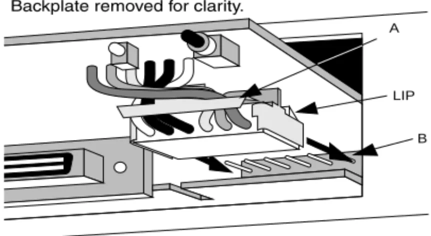
2 Refer to Figure 2-2. Using the insert/remove tab attached to the connector (A), push the connector into the socket (B) on the card below the Module. The connector has a lip on the upper face. Ensure that the lip is facing upwards, and that the pins in the socket align correctly with the connector. Push the connector in fully.
2-4 CHAPTER 2: INSTALLATIONAND SETUPFOR MANAGEMENT
Figure 2-2 Inserting The Hub 10 Module
WARNING: During installation, both the insert/remove tab and the lip
on the connector must be facing the module’s printed circuit board (see Figure 2-3). This means that the connecting wires will be twisted as shown in that illustration below. Failure to ensure that the connector is correctly oriented can result in damage to the module when the unit is powered up.
Figure 2-3 Detail Of The Hub 10 Connector
3 Connect the management connector (C) to the unit expansion connector directly below it on the unit. Make sure the connectors are fully pushed in.
4 When the connectors are in place, slide the Module home fully into its
LIP A
Inserting the Hub 10 Module 2-5
5 Secure the module using the supplied longer screw and washer on the left-hand side of the cover, and the two original retaining screws on the right-hand side of the cover.
6 Return your Hub 10 unit to its usual position. If your Hub 10 unit is part of a stack, reconnect the units using the hub expansion cables, starting with the management unit. Connect the OUT port of the management unit to the IN port of the next unit in the stack. Connect the OUT port of the next unit to the IN port of its neighbor. Continue in this manner until all the units in the stack are connected. You can now power up the stack, as described in the section “Power Up Sequence” on page 2-6.
Removing the Hub 10 Module
If you need to remove the module, perform the following steps:
1 Disconnect all the units in the stack from the mains power supply. Disconnect the unit with the Module from the other units in the stack.
2 Unscrew the three module retaining screws and slide the Module partly out to expose the connecetors.
3 Disconnect the management connector.
4 Disconnect the module's power connector by pulling gently but firmly on its insert/removal tab.
5 Slide the module out from the unit.
6 If you are not fitting another module, replace the original blanking plate to aid the circulation of cooling air and prevent the entry of dust and debris into the unit. Use the two shorter retaining screws you have just removed, plus the screw kept with the original blanking plate.
2-6 CHAPTER 2: INSTALLATIONAND SETUPFOR MANAGEMENT
Power Up Sequence
When any unit in the stack is powered up, the Module will reset all the units in the stack. Therefore, to avoid an unnecessary number of resets, power up any other units in the stack before powering up the unit containing the Module.
Connect the mains power cable to the unit with the Module installed, and switch on at the mains socket. The module will perform tests on all units in the stack, and the unit will run through its self-test sequence. This may take up to 20 seconds. The MGMT LED on the front panel of the unit will flash during the self-test.
At the end of the self test:
■ The MGMT LED on the front panel of the management unit will light
up steady green.
■ The appropriate UNIT number LED on each unit in the stack will light.
If the MGMT LED is off, colored red or flashing, refer to “LEDs and Reset Button” on page 2-7.
As a default, the Module powers up the unit with:
■ A null IP address.
■ The serial port set to autoconfiguration. (Autoconfiguration applies to
baud rate only. Parity, character size and stop bits are fixed.)
■ All ports enabled.
The unit will function normally but you may need to configure some of these parameters before you can manage the unit, as explained in the sections “Connecting Management Equipment to the Serial Port” and
LEDs and Reset Button 2-7
LEDs and Reset Button
Two LEDs indicate the state of the Module: a red/green LED on the front panel of the management unit and an amber LED at the rear of the Module. The Reset button is situated at the rear of the Module. Front Panel MGMT LED
The LED marked MGMT on the front panel of the management unit shows the status of the installed Module.
:
If the measures suggested above fail to rectify the problem, please contact your supplier for further advice.
Rear Panel Configure LED and Reset Button
The rear panel of the Module has a single amber LED (referred to as the Configure LED) and a Reset button. Pressing the Reset button causes the Module to be reset. This has the same effect as executing the Reset command (see “Reset” on page 3-48). The Configure LED will go on for a few seconds after the Reset button is pressed.
Green (steady)
The Module is operational and no problems are indicated. Green
(flashing)
Software is being downloaded (see “Software Upgrade” on page 3-50) or a self-test is being performed (see “Fault Log” onpage 3-47 ).
Red A fault has been identified. If the agent software image is corrupted, the Module will automatically try to reload the software image from the last configured download.
Reset the unit (see “Rear Panel Configure LED and Reset Button”). Off There is no Module installed in the unit, or the unit cannot
identify the installed module. Check that you have installed the module correctly and that the connector cable is secure.
2-8 CHAPTER 2: INSTALLATIONAND SETUPFOR MANAGEMENT
Connecting Management Equipment to the Serial Port
This section describes how to connect and set up equipment to communicate with the Module via the serial port (out-of-band management).
By default, the Module will automatically configure its baud rate. You will need to set the character size (8), stop bit (1) and parity (none) settings of the connected equipment to work with the Module. Connection to the serial port may be direct or through modems, giving the options of local or remote management. The maximum rate the autoconfiguration function will detect is 9600 baud.
Cables of the appropriate type for connection to the serial port should be available from your supplier. If you wish to make up your own cables, refer to the pin-outs given in Appendix A.
Chapter 3 describes the VT100 management interface in detail. Connecting a VT100 Terminal
To connect a VT100 terminal directly to the serial port, you need a standard null modem cable. See Appendix A for the pin-out information. Connect one end of the cable to the serial port on the Module, and the other to the serial (RS232) port on the VT100 terminal. The Module automatically configures its baud rate as described above, but you must set the character size (8), stop bit (1) and parity (none) settings of the connected equipment to work with the Module. Refer to “Getting Started” on page 3-6 for details of how to get started with the VT100 management interface.
Connecting a VT100 Terminal Emulator
The workstation will need to run suitable terminal emulation software. Many VT100 terminal emulation packages are available. Refer to the user manuals of your particular terminal emulation package for details, or consult your supplier if you need further advice.
Managing over the Network 2-9
If you are using a PC, you need a null modem cable with an appropriate connector.
The Module automatically configures its baud rate to that of the terminal emulator, as described above. You must set the character size (8), stop bit (1) and parity (none) settings of the emulator to work with the Module. Refer to “Getting Started” on page 3-6 for details of how to get started with the VT100 management interface.
Connecting a Workstation Running SLIP
You can communicate with the Module via the serial port from a workstation running SLIP (Serial Line Internet Protocol). In this way, you can manage the stack using Telnet or SNMP out-of-band management. The cables you require to connect the workstation will depend on its manufacturer and model. The general guidance given above for terminals will be useful here. You must also configure your workstation to use SLIP. Consult the operator manuals of your workstation for details.
You must configure the serial port of the Module to accept SLIP. This involves setting up the SLIP parameters (address and subnet mask). You can set up the SLIP parameters using either a network connection or a serial port connection. Refer to “IP Addresses” on page A-5 if you are unsure of the values to use. The section “Setup” on page 3-10 explains how to set the parameters using the VT100 management interface.
Refer to “Getting Started” on page 3-6 for details of how to get started with the VT100 management interface.
Managing over the Network
This section describes how to set up equipment to allow you to communicate with the Module over the network (in-band management).
2-10 CHAPTER 2: INSTALLATIONAND SETUPFOR MANAGEMENT
Quick Start for SNMP Management Users
This section describes briefly how to get started if you wish to use an SNMP manager, once you have installed and powered up the Module. It assumes you are already familiar with SNMP management. Refer to the sections which follow for more details. Appendix A contains more information about IP and IPX addresses.
■ If you are using the IPX protocol, the Module will be allocated an IPX
address automatically. You can start the SNMP manager and begin managing the stack.
■ If you are using IP and have a BootP server on your network, the IP
parameters will be automatically loaded and brought into use.
■ If you are using IP and no BootP server, you will need to configure the
stack's IP parameters before the SNMP manager can communicate with the stack. To do this, perform the following steps:
1 Connect a VT100 terminal (configured to 9600 baud, character size 8, stop bit 1, parity none) to the Module's serial port.
2 Log on to system (see “Logon” on page 3-7).
3 Select Management Setup from the Main Menu. (See “Main Menu” on page 3-9.)
4 Use the Management Setup screen (see “Setup” on page 3-10) to enter the IP parameter details.
5 Reset (see “Reset” on page 3-48) the Module. You can now begin managing the stack with the SNMP manager.
Using Telnet
Any Telnet facility that emulates a VT100 terminal should be able to communicate with the Module over the network. Up to three active Telnet sessions can access the Module concurrently. If a connection to a Telnet session is not closed, but is lost inadvertently, the connection will be closed by the Module after between 2 and 3 minutes of inactivity.
Managing over the Network 2-11
To set up Telnet communications, you first need to connect to the Module using serial port access and enter certain parameters. If you wish to use the VT100 interface to set up parameters including trap addresses, perform the following steps.
1 Connect a VT100 terminal or emulator to the serial port, and logon using the VT100 interface as described in “Getting Started” on page 3-6.
2 Display the Setup screen. Enter the Device IP Address and Device SubNet Mask of the stack, and the Default Router address if necessary, if you know them. If you have a BootP server on your network and wish to assign the details automatically, you may use the BootP facility. Refer to the documentation with your BootP server and “Setup” on
page 3-10 for details of how to do this.
3 Logoff from the VT100 interface.
You can now start a Telnet management session. Make sure that your Telnet application is emulating a VT100 terminal. To open the Telnet session, you must specify the IP address of the stack that you entered in step 2 above. Check the user manual supplied with the Telnet facility if you are unsure how to do this.
Once the connection is established, you will see the main banner of the VT100 management interface and you may log on. The VT100
management interface is described in detail in Chapter 3. Using an SNMP Network Manager
The Transcend WorkGroup and Enterprise Network Management Applications will enable you to get the best out of your SuperStack II Hub 10 units. Any SNMP based network manager can manage SuperStack II Huub 10 and LinkBuilder FMS Series units, provided the MIB (Management Information Base) is installed correctly at the management station. The MIB defines what information is available from the stack through the Module, how that information is structured, and how the SNMP network manager can read and update it.
The use of 3Com network managers is not described in detail in this manual. For more information, contact your supplier.
2-12 CHAPTER 2: INSTALLATIONAND SETUPFOR MANAGEMENT
To manage the stack with an SNMP network manager from another vendor, you need to use the appropriate MIB file. The concise SNMP MIB file for the SuperStack II Hub 10 Series is available free on the Ask3Com bulletin board (see Appendix B).
Refer to the manual accompanying your chosen network manager for details of how to proceed. If you wish to set up SNMP traps, in some cases you may have to configure the Module locally.
3Com network managers such as Transcend WorkGroup Manager for
Windows can automatically configure the Module to send traps to
them.
To set up SNMP communications, you first need to connect to the Module using serial port access and enter the IP configuration of the stack. Use the VT100 interface to set up parameters including trap addresses. Perform the following steps:
1 Connect a VT100 terminal or emulator to the serial port and logon using the VT100 interface. Refer to “Getting Started” on page 3-6 for details of how to do this.
2 Display the Setup screen (see “Setup” on page 3-10). If using IP, enter the Device IP Address and Device SubNet Mask of the stack, and the Default Router address if necessary, or use the BootP facility (see “Using Telnet” on page 2-10). If using IPX, the stack will have an address automatically allocated.
3 Display the Trap Setup screen (see “Trap Setup” on page 3-13). Enter the IP or IPX address of each network manager that you want to receive traps.
4 Logoff from the VT100 interface.
5 Reset the Module (see “Reset” on page 3-48) to bring the IP parameters into operation.
3
U
S
I
N
G
T
H
E
VT100
M
A
N
A
G
E
M
E
N
T
I
N
T
E
R
F
A
C
E
Introduction
This chapter starts with an overview of the VT100 user interface. It describes the screens and how to navigate between them. A map of all the screens is given, to help you to access any chosen screen.
The remainder of this chapter is divided into sections that cover management tasks. These sections broadly follow the division
suggested by the main menu. Each screen is described, and the access level needed to access the screen is indicated. Access levels are a security measure, and are described in “Logon” on page 3-7.
User Interface
We suggest you read through this section before you use the facility for the first time. After, you should only need it for reference.
Screens
3-2 CHAPTER 3: USINGTHE VT100 MANAGEMENT INTERFACE
Figure 3-1 An Example Screen
Screens are divided into three main areas:
■ The header area, at the top of the screen, displays a title which tells you
the subject of the screen.
■ The main part of the screen shows management information. The
components of this part of the screen are described in “Screen Components” on page 3-2.
■ The message area, at the bottom of the screen, is used to display
information and error messages.
The displayed screens may not be identical to those illustrated in this chapter. The contents of screens depend on your access level and the configuration at your installation. Access levels are described in the section “Screen Components” on page 3-2 .
Screen Components
The main part of a typical screen contains several different types of item. Table 3-1 gives an example of each component, and explains its use.
In the descriptions of the options given in this chapter, the default values are underlined.
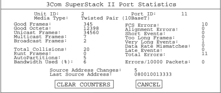
Errors/10000 Packets: FCS Errors:
Alignment Errors: Short Events: Too Long Frames: Very Long Events: Data Rate Mismatches: Late Events: Total Errors: 10 0 0 0 1 0 0 11 0 Total Collisions: Runt Frames: AutoPartitions: Bandwidth Used (%): Good Frames: Good Octets: Unicast Frames: Multicast Frames: Broadcast Frames: 345 12398 34560 7 2 20 0 5 6
CLEAR COUNTERS CANCEL 3Com SuperStack II Port Statistics
Unit ID: 2 Port ID: 11 Media Type: Twisted Pair (10BaseT)
Source Address Changes: 5
User Interface 3-3
Table 3-1 Screen Components
Component Type Description
◆Enabled◆ Choice Field Text enclosed in markers is a list, from which you can select one option only.
To cycle through the options, press [Space].
[005634] Entry Field Text enclosed in square brackets on the screen is an Entry Field. An Entry Field allows you to enter different types of data from the keyboard. This may be text, decimal or hexadecimal data. In some cases an Entry Field will have a default entry. To replace the default, simply type in a new value for this field. The default entry will be erased.
Password entry fields are hidden, which means that the characters you type are not shown on the screen.
To delete a single character, use [Delete] on a VT100 terminal or [Backspace] on a PC.
Address: Read-only information
Text not enclosed in markers or square brackets is information that you cannot change.
OK Button Text for a button is shown in upper-case letters. A button carries out an action. A menu screen such as the Main Menu consists of a number of buttons arranged in a column. Other screens have a row of buttons at the bottom.
To actuate a button, move the cursor to the button and press [Return].
The OK and CANCEL buttons appear on many screens. OK updates the stack according to the data in the fields of the screen, then returns you to the previous screen. CANCEL returns you to the previous screen without applying any changes
monitor manager security
List Box A list box allows you to select one or more items from a list. Selected items are indicated by an asterisk (*) next to the item. To select a single item, move the cursor (using the arrow keys) until the item is highlighted, then press [Return]. To select more than one item: for each item, move the cursor until the item is highlighted, then press [Space] to select the item. (Pressing [Space] again deselects the item). When all the desired items are selected, press [Return].
3-4 CHAPTER 3: USINGTHE VT100 MANAGEMENT INTERFACE
Special Keystrokes
As well as the keystrokes described above, there are several other keystrokes for controlling the VT100 interface. These keystrokes allow you to move the cursor around the screen, enter information and move from one screen to another.
When you have finished entering or changing data, [Ctrl]+[B] is very useful for skipping over the remaining fields.
If you are using Telnet or a terminal emulation program, you may find
that some control keys do not operate, or that they activate other functions. The Windows terminal emulator uses [Ctrl] + [H] as backwards deletion, whereas others use it for backward cursor
movement.Consult the manual accompanying your Telnet or terminal
emulation software before using the control keys. [Tab] Moves the cursor from one field to the next. [Ctrl]+[B] Moves the cursor to the next button.
[Ctrl]+[P] Returns you to the previous screen without actioning any inputs. [Ctrl]+[R] Refreshes the screen.
User Interface 3-5
Screen Map
3-6 CHAPTER 3: USINGTHE VT100 MANAGEMENT INTERFACE
Getting Started
This section covers logging on to the facility, displaying the main menu and logging off.
Main Banner
If you are using a VT100 terminal connected (directly or via modems) to the serial port, you need to perform the wake-up procedure. To do this, type [Return] [Return] at the terminal.
By default, the Module will automatically configure the baud rate of the serial port to operate with the connected terminal or modem, provided the parity, stop bits and character size are identical.
If you are using Telnet or SLIP, the wake-up procedure is performed automatically.
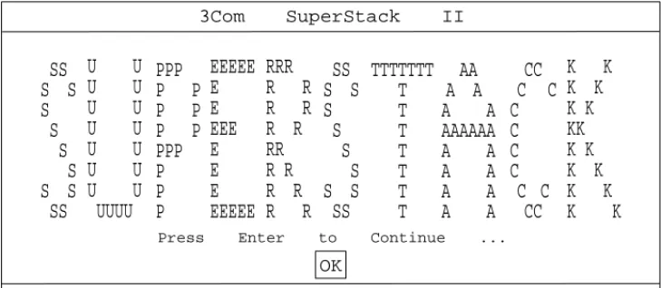
When the wake-up procedure is successfully completed, the main banner is displayed.
Figure 3-2 Main Banner Screen
The main banner screen has a concealed field which can be revealed using an SNMP manager, by entering text in the sysName MIB object. This field is convenient for defining the Module you are accessing.
Press Enter to Continue ...
3Com SuperStack II
OK
AA
A A
A A
AAAAAA
A A
A A
A A
A A
PPP
P P
P P
P P
PPP
P
P
P
CC
C
C
C
C
C
C
C C
CC
TTTTTTT
T
T
T
T
T
T
T
EEEEE
E
E
EEE
E
E
E
EEEEE
RRR
R R
R R
R R
RR
R R
R R
R R
SS
S S
S
S
S
S
S S
SS
SS
S S
S
S
S
S
S S
SS
U U
U U
U U
U U
U U
U U
U U
UUUU
K K
K K
K K
KK
K K
K K
K K
K K
Getting Started 3-7
If you cannot see the main banner or it displays incorrectly, it may be that:
Your terminal is not configured as a VT100 terminal.
Check that your terminal is setup to operate with acceptable parameters for the serial port (see the section “Serial Port Setup” on page 3-15). The autoconfigure option will only operate if your terminal
uses correct parameters for the Module. The maximum speed is 9600
baud.
Autoconfigure is disabled.
If you are unable to obtain the banner screen, it is possible that the autoconfigure option has been disabled. Check the configuration of the terminal.
If you cannot resolve the problem, refer to Appendix C for further troubleshooting information.
Once the Main Banner screen is displayed, press [Return] to display the Logon screen.
Logon
You must enter your user name and password to be able to use the management facility. The Logon screen is shown below.
Figure 3-3 Logon Screen
3Com SuperStack II Logon
OK
User Name: Password:
[ ] [ ]
3-8 CHAPTER 3: USINGTHE VT100 MANAGEMENT INTERFACE
If you are logging on for the first time (after installation or initialization), use one of the default user names and passwords shown in Table 3-2. The user name to use depends on which access level you require.
At the earliest opportunity, the system manager should change the
passwords for the default users. The system manager will need to logon as ’manager' and ’monitor' to change their passwords. The section “Edit User”on page 3-21 explains how to change a password.
Initializing the stack returns the passwords to their default values (see the section “Initialization” on page 3-49 ).
If you are not logging on as one of the default users, your system manager will have assigned you a user name and password. The user name determines which of the three access levels (monitor, manager or security) you have.
The user name and passwords are case sensitive. To logon to the facility, enter your user name and password in the appropriate fields and select OK. The Main Menu screen will be displayed.
Table 3-2 User Names And Passwords
User Name
Default
Password Access Level monitor monitor monitor
You can access but not change the operational parameters of the stack.
manager manager manager
You can change the operational parameters of the stack but cannot add or delete users, download software or initialize the stack. security security security
You can access all the screens and change all manageable parameters.
Getting Started 3-9
Main Menu
The Main Menu screen is illustrated below.
Figure 3-4 Main Menu
If you are using the management facility for the first time, we suggest that you:
■ Set up logons for any other users and assign each user an appropriate
security level. See “Local Security” on page 3-18.
■ Assign new passwords for the default users. See “Edit User” on
page 3-21.
To carry out a particular management task, scroll to the relevant option and press [Return]. The remaining sections of this chapter describe the various Main Menu options.
Logoff
If you have finished using the facility, select the Logoff option from the bottom of the main menu. If you accessed the facility using a Telnet session or modem connection, the connection will be closed automatically.
3Com SuperStack II Main Menu
REPEATER MANAGEMENT USER ACCESS LEVELS STATUS
SETUP SELF TEST
SOFTWARE UPGRADE INITIALIZE
RESET
REMOTE POLL LOGOFF
3-10 CHAPTER 3: USINGTHE VT100 MANAGEMENT INTERFACE
Auto Logout
There is a built-in security timeout on the VT100 interface. If you do not press any keys for three minutes, the management facility will warn you that the inactivity timer is about to expire. If you do not press a key within 10 seconds, the timer will expire and the screen will be locked. (Any displayed statistics will continue to be updated, however.) When you next press any key, the display changes to the Auto Logout screen. This screen is shown below.
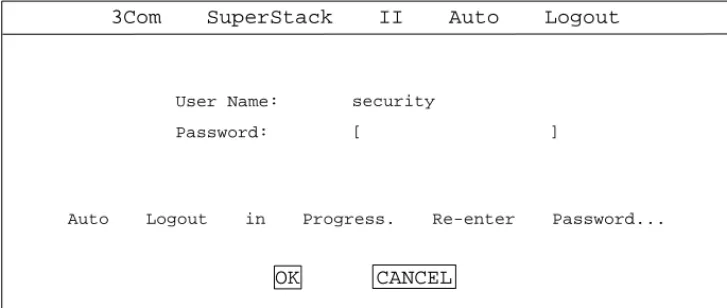
Figure 3-5 Auto Logout Screen
The Auto Logout screen requests you to enter your password again. If the password is correctly entered, the screen that was active when the timer expired is re-displayed. If you make a mistake in entering your password, you will be returned to the Logon screen.
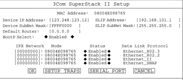
Setup
You use the Setup screen to configure IP, IPX and SLIP parameters for the stack. This screen also provides access to other screens for you to set up traps and serial port parameters.
3Com SuperStack II Auto Logout
Auto Logout in Progress. Re-enter Password...
User Name: Password:
security
[ ]
Setup 3-11
Figure 3-6 Setup Screen
MAC Address (Read-only) The MAC address of the Module. This cannot
be changed.
Device IP Address (Text Field) If using IP, you will need to enter a
unique IP address for the stack. (See “IP Addresses” on page A-5.) You may use the BootP facility (see below) if your network has a BootP server, or enter it manually. If you do not know the address, consult your network administrator. If you change the device IP address, you must reset the Module to effect the change.
Device SubNet Mask (Text Field) If using IP, enter a suitable subnet
mask. BootP will do this automatically. For a class B IP address, 255.255.0.0 is suitable. Check with your network administrator if you are unsure. If you change this field, reset the Module to effect the change.
Default Router (Text Field)If necessary, enter the IP address of the
default router on your network. BootP will do this automatically. If you change this field, reset the Module to effect the change.
SLIP Address (Text Field) SLIP (Serial Line Internet Protocol) allows IP to
run over the serial port instead of the network. SLIP allows you to use out-of-band Telnet or SNMP management, either locally or remotely via a modem. SLIP will operate with a SLIP address of 192.168.101.1.
3Com SuperStack II Setup
OK SETUP TRAPS SERIAL PORT CANCEL
IPX Network Node Status Data Link Protocol
[00000000]: [00000000]: [00000000]: [00000000]: 08004E098765 08004E098765 08004E098765 08004E098765 Enabled Enabled Enabled Enabled Ethernet_802.3 Ethernet_802.2 Ethernet_II Ethernet_SNAP ◆ ◆ ◆ ◆ ◆ ◆ ◆ ◆
Device IP Address: Device SubNet Mask: Default Router: BootP Select: [123.248.123.12] [FFFF0000 ] [0.0.0.0 ] Enabled ◆ ◆ SLIP Address: SLIP SubNet Mask:
[192.168.101.1 ] [255.255.255.0 ] 08004E098765
3-12 CHAPTER 3: USINGTHE VT100 MANAGEMENT INTERFACE
If you enter a SLIP address, it should show a different network from the stack that you are managing. Check with your network administrator if you are unsure. If you change this field, reset the Module to effect the change.
If you require more information about SLIP, read the Internet Activities Board document RFC 155
SLIP SubNet Mask (Text Field) Enter a suitable subnet mask. For a class
C address, 255.255.255.0 (the default setting) is suitable. Check with your network administrator if you are unsure. If you change this field, reset the Module to effect the change.
If you are using SLIP, ensure that Flow Control is not set to XON/XOFF (see “Serial Port Setup” on page 3-15).
BootP Select (Choice Field) Enabled/Disabled
When enabled, BootP allows you to download the IP address, the SubNet Mask, and the Router IP address from a BootP server on your network. When operative, BootP checks that a valid IP address is not installed before sending out requests for the data. It will keep on sending requests for data until one of three conditions is satisfied:
■ BootP is disabled,
■ a valid BootP reply is received, ■ or, you enter the address manually.
When the IP parameters have been received, the Module will reset automatically. No management commands are possible while the module reboots and self-tests.
The following four fields are used for IPX addressing.
IPX Network (Text Field)This field shows the address of the network
for this protocol. This address is learned automatically from the local IPX router or NetWare File Server, and you should not need to change it.
Setup 3-13
Node (Read-only) This field shows the node address of the repeater
stack, which is learned automatically.
Status (Choice Field) Enabled / Disabled
This field shows whether the data link protocol is enabled. Choose
Disabled if you wish to prevent access for any reason, such as security considerations.
Data Link Protocol (Read-only)This field shows the name of the IPX
data link layer protocol.
OK (Button) Press [Return] when the OK button is highlighted to action your selections for this screen. You will be returned to the main menu.
If you have changed the parameters, you will need to reset the Module to effect the changes. Refer to the section “Reset” on page 3-48.
SETUP TRAPS (Button) Press [Return] when the SETUP TRAPS button is
highlighted to set up the parameters for traps (see “Trap Setup” below).
SERIAL PORT (Button) Press [Return] when the SERIAL PORT button is
highlighted to set up the RS-232C port parameters (see “Serial Port Setup” on page 3-15).
CANCEL (Button) Press [Return] when the CANCEL button is
highlighted to abandon this screen without actioning any changes, and return to the main menu.
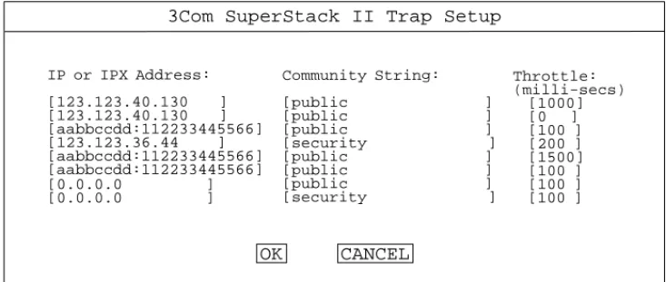
Trap Setup
Traps are messages sent across the network to an SNMP network manager, such as Transcend WorkGroup Manager for Windows. Traps can alert the system administrator to faults or changes in the stack.
Your Transcend SNMP network manager may automatically set up the
trap destination addresses for you. Check the documentation accompanying the product.
You access the Trap Setup screen by selecting the SETUP TRAPS button on the Setup screen.
3-14 CHAPTER 3: USINGTHE VT100 MANAGEMENT INTERFACE
Figure 3-7 Trap Setup Screen
IP or IPX Address (Text Field) Enter the IP or IPX address of the remote
network management station to which SNMP traps should be sent.
Community String (Text Field) The community string allows a very
simple method of authentication between the Module and the remote network manager. You can enter any text string of up to 32 characters (case sensitive!).
The remote network manager must be configured to look for traps sent with this community string, otherwise it will ignore the traps. The default community string is public.
Throttle (Text Field) To prevent a remote network manager receiving
too many traps at once, you can configure the stack to transmit traps with a delay between each trap. If several traps are generated at once, they will be transmitted with the specified delay between them. The unit of throttle is one thousandth of a second. The default value is 100, which gives a delay of one tenth of a second between each
transmission. If you set the throttle to 0, traps will be sent as soon as they are generated.
3Com SuperStack II Trap Setup
OK CANCEL
[0.0.0.0 ]
[0.0.0.0 ]
IP or IPX Address:
[123.123.40.130 ]
[123.123.40.130 ]
[aabbccdd:112233445566] [123.123.36.44 ] [aabbccdd:112233445566] [aabbccdd:112233445566] Community String: [public ] [public ] [public ] [security ] [public ] [public ] [public ] [security ] Throttle: (milli-secs) [1000] [0 ] [100 ] [200 ] [1500] [100 ] [100 ] [100 ]
Setup 3-15
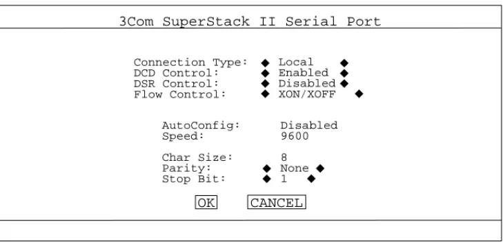
Serial Port Setup
You can access the Serial Port Setup screen by actuating the SERIAL PORT button on the Setup screen.
Figure 3-8 Serial Port Setup Screen
If you alter the serial port parameters and select OK, you will terminate any existing session using the serial port. Ensure that the connected equipment's serial port parameters are set to match the new configuration. This will allow you to continue to access the
management facility using the equipment after you change the serial port parameters.
If you change the serial port parameters with Auto Config already set to Enabled, or if you change Auto Config to Enabled, you will need to perform the wake-up procedure (see “Main Banner” on page 3-6) before communication is re-established.
Connection Type (Choice Field) Local / Remote
Select Remote if you want to manage the stack via a modem. DCD Control and DSR Control will be enabled. Otherwise, leave this parameter at the default setting.
DCD Control (Choice Field) Enabled / Disabled
Check in the manual for your modem if you are not sure of the correct setting.
3Com SuperStack II Serial Port
OK CANCEL
AutoConfig: Speed: Char Size: Parity: Stop Bit: Disabled 9600 8 None 1 Connection Type: DCD Control: DSR Control: Flow Control: Local Enabled Disabled XON/XOFF ◆ ◆ ◆ ◆ ◆ ◆ ◆ ◆ ◆ ◆ ◆◆
3-16 CHAPTER 3: USINGTHE VT100 MANAGEMENT INTERFACE
DSR Control (Choice Field) Enabled / Disabled
If DSR Control is enabled, the management port will be logged out if DSR is deasserted. Check in the manual for your modem if you are not sure of the correct setting.
Flow Control (Choice Field)
XON/XOFF / NONE / RTS - CTS Unidirectional / RTS - CTS Bidirectional Select the flow control option that corresponds with your terminal or modem.
Auto Config (Choice Field) Enabled / Disabled
The Module can automatically configure the terminal speed to work with your VT100 terminal. Note that the setting made by automatic
configuration is not displayed on the screen. The displayed setting is that which will be adopted when automatic configuration is next disabled. Set this field to Enabled if you require automatic configuration.
To start automatic configuration detecting and setting the correct speed, the wake-up procedure (typing [Return] [Return]) must be performed.
Speed (Choice Field) 1200 / 2400 / 4800 / 9600
Select the baud rate for your terminal or modem. Check in the manual for your terminal or modem if you are not sure of the correct setting.
Char Size (8), Parity (NONE) and Stop Bit (1) are fixed.
Attempts to set invalid serial port parameters will be rejected. All parameters will be reset to their default values.
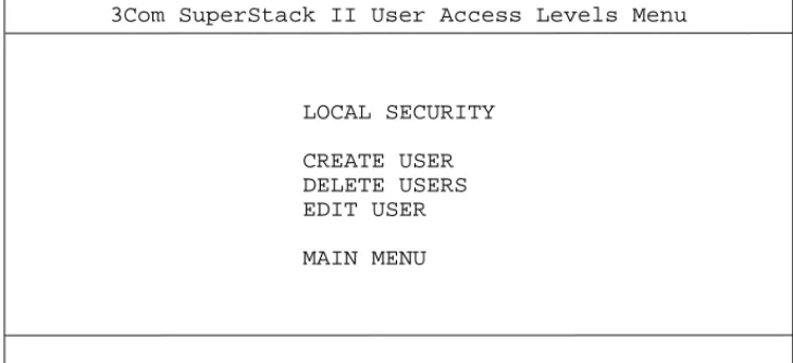
User Access Level 3-17
User Access Level
The User Access Level screen provides a menu to access four further screens.
Figure 3-9 User Access Level Menu
Local Security This screen allows you to enable or disable access to
the management facility, for each combination of access method (serial port, Telnet or SNMP) and access level.
Create User This screen allows you to create another user who can
access the management facility, in addition to the default users.
Delete Users This screen allows you to remove users, other than the
default users.
Edit User This screen allows you to change your own password and
community string.
The first three screens are only available for users with security access level. Select the option for the screen you require and press [Return]. 3Com SuperStack II User Access Levels Menu
LOCAL SECURITY
CREATE USER DELETE USERS EDIT USER
3-18 CHAPTER 3: USINGTHE VT100 MANAGEMENT INTERFACE
Local Security
You can access the Local Security screen by actuating the LOCAL SECURITY button on the User Access Level screen. This option is available only for users with security access level.
Figure 3-10 Local Security Screen
The Local Security screen shows a table displaying every combination of access method (serial port, Telnet or SNMP) and access level. For example, the top left choice field shows whether serial port access by users with
monitor access level is enabled or disabled. The access levels are defined as:
■ Monitor - This allows the user to view the essential operations of the
stack and to establish whether or not the stack is operating correctly. A user at this level cannot change the operating parameters of the stack or gain access to any of the setup menus.
■ Secure Monitor - In this implementation, Secure Monitor has the same
rights as Monitor.
■ Manager - This allows the user to monitor and change the operational
parameters of the stack. The user cannot create or delete other users, re-initialize the stack or download a software image.
3Com SuperStack II Local Security
Enabled Enabled Enabled Enabled Disabled Enabled Enabled Enabled Enabled Enabled Enabled Enabled Enabled Enabled Enabled Serial Port Remote Telnet Community-SNMP ◆ ◆ ◆ ◆ ◆ ◆ ◆ ◆ ◆ ◆ ◆ ◆ ◆ ◆ ◆ ◆ ◆ ◆ ◆ ◆ ◆ ◆ ◆ ◆ ◆ ◆ ◆ ◆ Monitor Secure Monitor
Manager Specialist Security
User Access Level 3-19
■ Specialist - In this implementation, Specialist has the same rights as
Manager.
■ Security - This level of security allows a user access to all the
management operations. This level of security should be assigned only to the system administrator or somebody with the system
administrator's responsibilities.
All the fields are choice fields. The options for each field are Enabled
(the default) or Disabled.
To prevent you from locking yourself out from the stack completely, serial port access is always kept enabled for the security access level. Make any changes you require, then move the cursor to the OK button and press [Return]. Remember that you can use [Ctrl]+[B] to jump to the OK button.
Serial Port (Choice Field) Enabled / Disabled
To prevent access to the management facilities via the serial port, disable access to the facility for each access level. To allow you to configure the stack locally in the event of problems on your network, we suggest that you change the default password (see “Edit User” on page 3-21) for the permanently-enabled security access level.
Remote Telnet (Choice Field) Enabled / Disabled
Telnet is an insecure protocol. You may wish to disable all access to the management facilities via Telnet if there is important or secret data on your network.
Community SNMP (Choice Field) Enabled / Disabled
The stack can be managed via SNMP using a remote network manager such as Transcend WorkGroup Manager for Windows. Community SNMP does have some simple security features but it is an insecure protocol. You may wish to disable all access to the management facilities via Community SNMP if there is important or secret data on your network.
3-20 CHAPTER 3: USINGTHE VT100 MANAGEMENT INTERFACE
Create User
You access the Create User screen by actuating the CREATE USER button on the Security screen. This option is available only for users with security access level.
Use this screen to add new users. There can be up to 10 users, including the three default users. Up to three users can concurrently access the management facility using Telnet. There is no limit to the number of SNMP remote management sessions.
Figure 3-11 Create User Screen
User Name (Text Field) Enter the name of the user. The name can be
up to 10 characters. The user name is case sensitive.
Password (Text Field) Enter a password for this user. The password
can be up to 10 characters. The password is case sensitive and will not be displayed on the screen.
Access Level (Choice Field)
Monitor / Secure Monitor / Manager / Specialist / Security
Enter an appropriate access level for the new user by cycling through the options using the space bar.
3Com SuperStack II Create User
OK CANCEL
User Name: Password: Access Level: Community String:
[bob ] [ ]
Monitor
[bob ]
User Access Level 3-21
Community String (Text Field) By default, the community string is the
same as the User Name. You can change this string if you wish, to any text string of up to 32 characters. The community string is used only for SNMP access. The remote network manager must be configured to use the same community string.
Delete Users
You access the Delete Users screen by actuating the DELETE USERS button on the Security screen. This option is available only for users with security access level.
Figure 3-12 Delete Users Screen
Select the users to delete from the List Box using the spacebar, then move the cursor to the DELETE USERS button and press [Return]. You cannot delete the current user (in other words, the user name you used to logon) or any of the default users (monitor, manager or security). Edit User
You access the Edit User screen by actuating the EDIT USER button on the Security screen. Use this screen to change your own password or community string.
3Com SuperStack II Delete Users
User List
manager security bob sue george
monitor