Research Development Cell, Government College of Engineering, Jalagon (M. S), India
Area Efficient High Speed Fir Filter with
Using DA Algorithm
Amol V. Navalagire1, Pramod G. Ambhore2
Assistant Professor, Department of Electronic & Telecomm. Engineering, MIT(T), College, Aurangabad, India1
Assistant Professor, Department of Electronic & Telecomm. Engineering, MIT(T), College, Aurangabad, India2
ABSTRACT: Piece of document represents a different and simple methodology for design and implementation of digital signal processing (DSP) filters. We present design for finite-impulse response (FIR) in terms of area, delay, and throughput, also power optimization of finite-impulse response filter by using distributed arithmetic (DA). DA is
basically a bit-serial computation operation that performs for vector–vector multiplication for inner dot products in single step, which make different from normal multiply accumulate (MLA) logic for inner(dot) product computation. DA technique is a multiplier less circuit. Taking optimal advantage of the look-up table (LUT) based structure of field programmable gate array (FPGA). The performance of the bit-serial and bit-parallel DA technique for FIR filter design is synthesized and the results are compared to the conventional FIR filter design techniques. The manuscript present less latency and less area with exiting FIR filter stricture. Motivation about the design for achieves computational efficiency, high speed, and low area.
KEYWORDS: sum of product (SOP), lookuptable (LUT), multiply accumulate (MAC),Distributed Arithmetic (DA), FPGA.
I. INTRODUCTION
Most electronic devices such as phones, personal digital assistants, and hearing supports mostly require digital signal processing (DSP) for high performance. Various type of DSP operations are utilize in practice depending on requirement. Filtering is one of them in DSP operations, which most extensively used signal processing operations. Rigorous use of FIR filters in digital signal processing for high performance in terms of speed, area efficient and power consumption is constrained [1]. Also, Digital filters extensively used in all areas of electronic industry. This is because; they have the potential to attain much better signaling to noise ratios.FIR Filter at present recognized by two kinds of method. One is hardware implementation used the chips such as programmable digital signal processor (PDSP), Application-Special Integrated Circuit (ASIC) and field programmable gate arrays (FPGA). The other is software implementation used advanced language such as MATLAB. There is multiple ways to implement the digital FIR filter. Based on the design specification, careful choice of implementation method and tools can save a lot of time and work. Mat Lab is an excellent tool to design filters [2]. Other DSP algorithms are known to be multiply-accumulation (MAC) intensive. Completing a filter cycle, when using a conventional arithmetic unit, would take approximately N MAC cycle. This amount can be shortened with pipelining but can, nevertheless, be prohibitively long. This is fundamental problem when general purpose multipliers are used and which take significant large chip area; alternative methods used
Research Development Cell, Government College of Engineering, Jalagon (M. S), India
This manuscript is organized as follows: Section II explores the basic of MAC FIR filter. Section III describes main logic of DA technique and the basic idea about DA solutions. The proposed efficient DA FIR filter architectures are discussed in Section IV. A recognized result is discussed in Section IV.
II. FIR FILTER WITH SOP
MATLAB design used for filter response and generating coefficient tables, for implementing on FPGA tool. To program on FPGA, VERILOG hardware description language offers an easy way towards different implementation. In DSP, for a finite impulse response (FIR) filters impulse response is finite duration. It makes difference to infinite impulse response (IIR) filters, in terms of linear phase and stability. Show in Figure 1, discrete time FIR filter of order N in transform notations. It contains N- stage delay lines with N+1 taps. Output y is a linear time invariant (LTI) system determine by convolving its input signal x (n) with its impulse response h (n).
For a discrete-time FIR filter, the output is described by the following equation,
( ) = ∑ ( − )ℎ( )--- (1)
( ) = (0)ℎ(0) + ( −1)ℎ(1) + ( −2)ℎ(2) +⋯ ( − )ℎ( ).
FIG.1 FIR filter with MAC block
Where, constants h(k) are the filter coefficients and the variables, x(k) are the prior samples of a data source. In other domain as frequency transforming -whether the discrete Fourier or the fast Fourier transforms- the constants are the sine/cosine basis functions and the variables are a block of samples from a data source [7]. Hence Nth order filter required N+1 Coefficient, N+1 Multiplier, and N Adder. Equation (1) shows that multiplier-based filter implementations may become highly expensive in terms of area and speed, which nothing but more number of adder circuits for one multiplier. So, it require large portion of chip area. Consequently, power consumption is more.
III. DISTRIBUTED ARITHMETIC
A. DISTRIBUTED ARITHMETIC BACKGROUND:-
A was first studied by Croisier et al. and it familiarize by Peled and Liu. Patrick Longa introduced the structure of
the FIR filter using DA algorithm and the functions of each part. Sangyun Hwang examines power consumption of the filter using DA algorithm. DA is a bit-serial in nature architecture for vector- multiplication [6]. DA is so named because the arithmetic operations that appear in signal processing are not lumped fashion but it often distributed. This type of bit-serial operation used to compute the inner (dot) product of a constant filter coefficient vector and a variable input vector, when the coefficients pre knowledge.
An FIR filter of length k simply given as:
Research Development Cell, Government College of Engineering, Jalagon (M. S), India
In fixed point implementation two’s complement system is that of most popular signed number system. That’s because it’s possible to add several signed numbers, and as long as the final range is in the Nth bit range. We can ignore any overflow in arithmetic also.Input samples coded as N-bit two’s complement numbers as:
x(n−k) =− + b 2
Rearranging order of summation & making group some of product, we get final result of output as:
( ) =− ℎ( ) + [ ℎ( ) b 2 ]
IV. PROPOSED WORK /DESIGN
A. FIR FILTERS REALIZATION USING DA: -
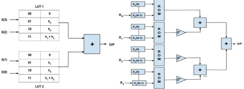
The main function unit of DA FIR filter consists of Look up Table (LUT), Shift registers and scaling accumulator. Filter implemented using DA in that input samples are used as addresses to access a series of LUTs. LUTs store the pre-computed value of filter coefficient. Filter coefficient value from MATLAB tool. LUT are basic component of FPGA, that kind of look up table logic store individual bit values. So memory access time is less, hence speed is substantial high. Distributed Arithmetic provides cost- effective structure in terms of area- time computation. Suggesting that, the filter of Nth order/tap means it contains N no. of input and N no. of filter coefficient, that require 2N possible combination location of LUT for storing pre computed values of coefficient. The filter input & coefficient are in binary format (but it not necessary for coefficient) from the equation, but not necessarily of the same word length. The simple block of DA FIR filters, shown in figure. Simultaneous, when applying the all Ith MSB bit to the LUT. Appropriate address location selected of LUT.
These location address data are getting at the output Jth. This output data directly store in accumulator & other input bit (I+1)th are applied, which select the appropriate location & produce the data at the output (J+1)th. This (J+1)th data shifted by one bit & store in accumulator. Another bit (I+2)th of all input applied simultaneous, which select LUT & data produced at the output (J+2)th. This output (J+2)th shifted by two bit & store it again in accumulator. Same procedure happens again up to last bit(I-bn)th of input. Finally all store data in accumulators are added or subtracted &
produce final output of filter. Let the filter inputs be
X0 =1 (001), X1 = 3 (011), X2 = 7 (111) & filter coefficient H0 = 2, H1 = 3, H2 = 1;
Step 1: Store the values in input buffer
Research Development Cell, Government College of Engineering, Jalagon (M. S), India
Enumeration N clocks for final, that’s N is the number of input variable bits, and sovereign of the number of input variables present in operation. For MAC logic, Nth order filter takes more area & delay required. Compared with DA logic it takes less area & delay. But, drawback is that, by increasing order of filter LUT size increase. Illustration shows LUT contain values for 3rd order FIR filter, shown in table 1. It requires 23=16 location as order increase LUT location also increase. These problem remove doing decomposition of LUT.Mat lab tool furnish coefficient & data sources; specified value.
B. PARTITION OF LUT UNIT IN TERMS OF SIZE:-
For lower order filters, the above technique holds good. But, for higher order filters, the size of the LUT also increases in power of two with order of the filter. This in turn increase size of requirement & reduces the performance. Filter order increase, size of LUT reduced to a reasonable level. Co-efficient is shown in table 1. For that LUT can be subdivided into a number of LUTs, called LUT partitions. After partition, each LUT operates on a different set of filter taps. Shown in figure 4, the result obtained from the partition block individually & finally together. Another size reduction technique Decomposition; nothing but control unit with LUT. Control unit any logic resources on FPGA.
FIG 4 - 3rd order FIR filter with partition method& Pipelined implementation of a DA FIR filter
C. PIPELINED ARCHITECTURE OF FIR FILTER IN TERMS OF SPEED:-
Additional speed increased by L partitioning of input data worlds. Effectively increase L-times memories with expanded accumulator for combing result. The data provided to LUT in serial pattern form of one bit at a time (BAAT), results in a slow computation. This limits the throughput (delay) of DA. To improve the throughput, DA can be configured to process multiple bits. For processing multiply bit pipelining used. Pipelining technique helps to a reduction in the critical path of operating data, which also increases the speed of operation. Although there is a slight increase in system resources and latency, but this technique increases the overall performance of the Filter. Each LUT operate on different tap order.
V. RESULT
Research Development Cell, Government College of Engineering, Jalagon (M. S), India
Fig5(A):Simulation 6-tap unsigned DA FIR filter using LUT partition&Simulation of pipelining DA FIR filter
lt of FIR filter using MAC block showing higher value than DA techniques. DA takes approximate less value in comparison parameter.
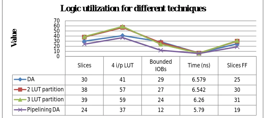
Lining difference of all proposed work is shown in Figure 6.
Fig 6: Chart of DA Technique Vs LUT partition Vs pipelining result
V. CONCLUSION
The proposed study of efficient simple DA algorithm for FIR filter was presented in this work. The excepted result was studied for 3-tap FIR filter on XILINX 9.1. In this study, the multiplier less FIR filter is implemented using DA contain main block of Look up Table, which then partitioning is involved. Memory resource on FPGA had less access time than multiplication time of multiply and accumulation block. Partition of LUT reduces memory size which is requirement for higher order. This technique reduces the delay, area, logic resources & power consumption. Further improvement done by processing multiply bit knows as pipelining. This pipelining architecture provides an efficient area- time power implementation which involves significantly less latency and less area- delay complexity when compared with existing structures for FIR Filter.
Slices 4 i/p LUT Bounded
IOBs Time (ns) Slices FF
DA 30 41 29 6.579 25
2 LUT partition 38 57 27 6.542 30
3 LUT partition 39 59 24 6.26 31
Pipelining DA 24 37 12 5.79 19
0 10 20 30 40 50 60 70
V
al
u
e
Research Development Cell, Government College of Engineering, Jalagon (M. S), India
REFERENCES
[1] R. Guo and L. S. DeBrunner, “Two high-performance adaptive filter implementation schemes using distributed arithmetic,” IEEE Trans. Circuits
Syst. II, Exp. Briefs, vol. 58, no. 9, pp. 600–604, Sep. 2011.
[2] R. Guo and L. S. DeBrunner, “A novel adaptive filter implementation scheme using distributed arithmetic,” in Proc. Asilomar Conf. Signals, Syst., Comput., Nov. 2011, pp.160–164.
[3] Meher P K , Chandrasekaran S and Amira A. FPGA Realization of FIR Filters by Efficient and Flexible Systolization Using Distributed Arithmetic [J]. IEEE Transactions on Signal Processing, 2008, 56(7): 3009~3017.
[4] Kim Kyung-Saeng, KwyroLee, “Low-power and area efficient FIR filter implementation suitable for multiple tape”, IEEE Transactions on VLSI Systems 11 (1)(February2003).
[5] P. K. Meher and S. Y. Park, “High-throughput pipelined realization of adaptive FIR filter based on distributed arithmetic,” in VLSI Symp. Tech.
Dig., Oct. 2011, pp. 428–433. [4] K. K. Parhi, VLSI Digital Signal Procesing Systems: Design and Implementation. New York: Wiley, 1999. [6] R.Wyrzykowski and S. Ovramenko, “Flexible systolic architecture for VLSI FIR filters,” Proc. Inst. Elect. Eng.—Comput. Digit. Techniques, vol. 139, no. 2, pp. 170–172, Mar. 1992.