tion
1Shinshu University, Nagano, Nagano, Japan
2Osaka Electro-Communication University, Neyagawa, Osaka, Japan
Abstract. We have developed a standard UV-LED light source mounted on an unmanned aerial vehicle (UAV), so-called theOpt-copter, for the calibration of the fluorescence detectors (FDs) of the Telescope Array experiment. The positioning accuracy of the UAV controlled by GPS is∼10 cm, which enables a precision calibration of the pointing directions of the FD phototubes. We report the hardware details of the device and the status of data analysis.
1 Introduction
The Telescope Array (TA) experiment located in Utah, USA aims at observing ultra-high-energy cosmic rays (UHECRs) with energies greater than 1018eV. TA utilizes two types of detectors, the fluorescent detectors (FDs) in three stations that measure fluorescens photons emitted by air molecules along a cosmic ray shower, and the sur-face detectors (SDs) that measure shower particles at the ground. The TA detectors are operational since May 2018 [1][2].
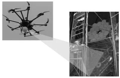
This report deals with the calibration systems for the TA FDs. The accuracy of the optical systems and photo-tube gains are key in the determination of arrival directions and energies of cosmic rays. One of the common methods to calibrate pointing directions of optical sensors is to use light sources whose positions are previously known with good accuracies, like stars. We developed a FD calibra-tion system with a high-luminosity UV LED mounted on an unmanned aerial vehicle (UAV) controlled by GPS with the accuracy of∼10 cm. Its position stability and porta-bility enables us to calibrate the optical system of our FDs with good pointing accuracies by a single standard light source for all the FDs at the three sites separated by 35 km each other. The conceptual image of this device, Opt-copter,is shown in Fig. 1.
2 The Opt-copter
The Opt-copter is composed of an unmanned aerial vehicle (UAV), a UV-LED as the light source, and several GPS modules (Fig. 2). The position accurary of the Opt-copter enables the calibration of FD phototubes with the accuracy of 0.1 degrees or even better.
∗e-mail: [email protected]
Figure 1.The conceptual image of measurement by Opt-copter.
2.1 UAV
We use a high-stability 8-rotor helicopter (DJIS1000+) to load the light source. The size of the UAV 400×400×500 mm (WxDxH) when the arms collapsed, and its portability with automatic leg and centrifugal propeller folding mech-anism helps works in wilderness at night. Both operations by manual control and by a programmed flight path are possible. A high-power and high-efficiency heat radiation motor and the all-carbon body frame of the vehicle real-ize a flight of 12∼15, with a 16000mAh lithium polymer battery. ThisS1000+is also designed to load a camera for aerial photography, and we use this room (∼ 30 cm3) to mount the light source and electronic devices. The maxi-mum load weight is 7 kg.
2.2 The flight controller
Figure 2. Opt-copter has 8 arms and all of them are able to be folded
Figure 3.Appearance of A3 as a UAV control device using GPS.
Figure 4.piksi is composed of two modules and record the rela-tive proposition of them
2.3 RTK-GPS
The opt-copter is designed to hover 300 m ahead of the FDs in calibration flights. The positioning accuracy of 3 m corresponds to a pointing accuracy of 0.6◦ at the dis-tance of 300 m (c.f. the field of view of each phototube is 1◦). For a phototube pointing calibration with the accuracy of 0.1◦, a positioning accurary of 0.5 m is needed, and the Real Time Kinetic GPS (RTK-GPS) system (Swift Nav-igation, Piksi) enables this (Fig. 5). RTK-GPS consists
Figure 5. Appearance of gps-based pulse generator (ublox, EVK-M8-TCXO)
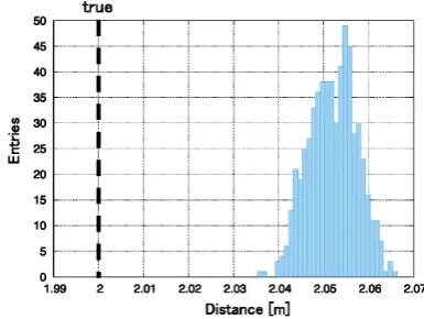
of two GPS modules, and records the relative position of the GPS antennas using the phase difference of the signals emitted from the GPS satellites. The position accuracy of RTK-GPS is typically 10 cm after GPS calibration more than 1.5 hours. We evaluated the positioning accuracy on the ground. The movement distance was measured 2 m and 10 moves, and RTK-GPS was calibrated for each of the tests and tried 10 times. The distribution of the mea-sured relative distances between the two modules is shown in Fig. 6, which exibits that the horizontal and vertical ac-curacy of RTK-GPS is better than 10 cm. By loading one GPS module of RTK-GPS on the UAV and placing the other at a reference point on the ground where the position is previously measured in good accuracy, it is possible to know actual positions of the UAV and the direction seen from the FDs.
Figure 6.Ranging accuracy of RTK-GPS on the ground.
2.4 The triggering system
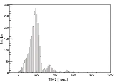
Figure 7. Time difference between pulse generator for light source and RTK-GPS measurment for ranging.
400
− −200 0 200 400
Time Diff [ns] 0
1000 2000 3000 4000 5000 6000 7000
Entries
Time Diff [ns]
Entries 36000 Mean −35.4 Std Dev 92.7
Figure 8. Time difference between pulser for FD trigger and pulser for light source.
of the Opt-copter light source image on the FD camera is as small as the size of a phototube, which was confirmed by our preparatory measurement hovering the UAV at the center of the field of view of an FD, the self-triggering of FD does not work for Opt-copter signals. Therefore we need a trigger generator for this to send trigger pulses both to FD and the light source in order that a measurement of the light source position, a UV-LED flash, and the FD data acquisition are made at the same time. The position mea-surements by the RTK-GPS as at the frequency of 10Hz, and we use two GPS-based pulse generator of 10Hz, one on the Opt-copter for LED flashes, and the other is to trig-ger the FD data acquisition. This frequency is well below the maximum trigger rate of the TA FD, 30 Hz. All the three GPS modules are presumably synchronized by the GPS-PPS signal every second. We compared the signal timing differences using an external high precision pulse generator that is also synchronized with GPS-PPS, and the GPS pulse for the Opt-copter as shown in Fig. 7. The time differences between the two GPS-based pulse generator, for the Opt-copter and for the FD trigger, is presented in Fig. 8. This shows that the synchronization of the GPS-based pulse generator is as good as 0.1µs, which is much smaller than the width of the UV-LED flash.
Figure 9. The light source mounted on the Opt-copter is con-sisted of 12 UV-LEDs attached on dodecahedron and a spherical diffuser
3 Operation and data
The position of the launching point of the Opt-copter ahead of each FD station is measured with good accu-racy in advance. The light source is designed to be seen from the FD at the distance of 300 m, and the vehicle flies around in the field of view of the camera with a position-ing accuracy of 10 cm, which corresponds to a directional accuracy of 0.02◦. Fig. 10 shows a bird’s eye view of an Opt-copter flight.
Figure 10.A bird’s-eye view of the flight
Figure 11.Measurement position by RTK-GPS on FD viewing field (Gray) and center of gravity of detected light by FD (Light gray).
gravity of the amount of received light indicates the posi-tion of the light source, and the RTK-GPS measures the relative position of the GPS antenna on the Opt-copter and the GPS antenna on the ground reference station. To com-pare the two, we project information by the RTK-GPS on the FD view (See Fig. 11.). The trajectory of the detected center of gravity appears to be biased to the center of each PMT, which is different from the position of the projected image by the RTK-GPS measurement. If the image of the light source is sufficiently smaller than the size of one pixel of the FDs (PMT), the center of gravity is biased towards the center of the PMT, which contains the main part of the image of the light source. By measuring the center-of-gravity shift when the measurement by the RTK-GPS is taken as the true position, it is expected that the optical characteristics of the FD such as the difference of the fo-cused spot can be obtained. We evaluate the correlation of the opening angles between the RTK-GPS and the cen-ter of gravity from the view cencen-ter of the FD. Figure 12 shows data of two FDs as examples. This difference is consistent with the construction records. In other words, it is suggested from the relationship between the RTK-GPS and the light receiving gravity center of the FD that it has sensitivity to the size of the focused spot in the vicinity of the visual field center of the FD. The plot shifts horizon-tally from the solid line in Fig. 12 if the field of view of our assumed FD and the actual field of view deviate.
4 Discussion
The Opt-copter showed the measurement performance of geometrical optics parameters for the current TA-FD. Fu-ture analysis will provide fine optical characteristics of FD. As a result, more advanced calibration can be ex-pected, reducing energy shower energy and systematic
er-Figure 12.Correlation of opening angle from the center of field of view of RTK-GPS and FD of detection center of gravity in two FDs.
ror of Xmax is expected.
Acknowledgements
ciate the assistance of the State of Utah and Fillmore offices of the BLM in crafting the Plan of Development for the site. Patrick Shea assisted the collaboration with valuable advice on a