Fuzzy Control Based Micro-grid System with a
Back to Back Converter
GOSULA SHIVA RAMULU M-tech student Scholar
Department of Electrical & Electronics Engineering, Scient Inst Of Engineering and T echnology College,
Ibrahimpatnam; Rangareddy (Dt); T elangana, India.
Email:[email protected]
B.SREENIVAS Associate Professor
Department of Electrical & Electronics Engineering, Scient Inst Of Engineering Technology College, Ibrahimpatnam;
Rangareddy (Dt); T elangana, India. Email:
[email protected]
Abstract: This concept proposes to use a back-to-back converter as the inter link between a utility grid and a micro grid. To justify this proposal, two modes of operation are explained and the benefits of the back-to-back converter over conventional static switches are shown. In mode-I, the inter-link converter injects pre specified amounts of active and reactive power to the micro grid. This mode is identified as Fuzzy control mode. Mode-2 is the voltage control mode in which, the back to back converter controls the voltage of the micro grid and maintains the power quality of the current drawn from the utility grid in spite of nonlinear and unbalanced loads in the micro grid. Abstract-This paper proposes to use a back-to-back converter as the interlink between a utility grid and a micro grid To justify this proposal, two modes of operation are explained and the benefits of the back-to-back converter over conventional static switches are shown. In mode-I, the inter-link converter injects pre specified amounts of active and reactive power to the micro-grid. This mode is identified as Fuzzy control mode. Mode-2 is the voltage control mode in which, the back to back converter controls the voltage of the micro-grid and maintains the power quality of the current drawn from the utility grid in spite of nonlinear and unbalanced loads in the micro-grid.
Keywords-microgrid; back-to-back; inter-link converter; voltage control mode; PQ control mode
I INTRODUCTION
Micro grids have been introduced as alternatives to conventional centralized grids. These systems will play an important role in the future of smart grids. A Microgrid can usually operate either in grid-connected or island mode. Electro -static switches are normally used to make an A C microgrid co mpletely separated fro m the utility in an island mode of operation. Therefore, the critical loads can survive fro m the d isturbances in frequency/voltage of the utility grid. In this condition, the utility grid has been lost as a stiff resource.
The static switches can be replaced with an ac-dc-ac converter. Th is back-to-back (b-to-b)
converter as an interlink converter can offer the following benefits:
Isolating the microgrid fro m the utility while keeping the flow of power between them.
Removing the necessity of the
resynchronization, when the microgrid is intended to reconnect to the utility grid.
Facilitating power flo w control between the microgrid and the utility.
In recent years, the idea of using ac-dc-ac converter as the interlin k between microgrid and utility grid has been proposed, but its application limits to power flo w control [1]. In this work, it is intended to extend this application to another voltage control mode of operation. The b-to-b converter also has been used to interlin k two or mo re independent micro grids operating at different voltage and frequency [2].
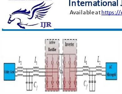
Fig.1. Power circuit of the back to back converter
As shown in Fig.1, the b-to-b converter is used with an LCL filter on both sides to attenuate the converter switching ripples. In the stationary frame used in this paper, the proportional resonant (PR) controller must be used for tracking sinusoidal references. The PR controller is recently used for several purposes such as, reactive power control in island microgrid [8] and harmon ic sharing in the microgrid [9]. In the next sections , the approaches used for designing the control loops in the voltage and the PQ control modes, are explained using the methods introduced in [3]. Several approaches have been used for parameter tuning of the multi -loop controllers in the literature, such as the iterative process [4] and pole-zero cancellation [5].
Fig.2. Back to back converter operated in the PQ control mode (mode-1) or voltage control mode (mode-2)
II POW ER CIRCUIT STRUCTURE
A Schematic diagram of the system under study. It consists of an active rectifier with an LCL filter, a DC-link capacitor and an inverter with another LCL filter. The parameters of the LCL-filters are determined according to some factors such as current ripple, resonant frequency, the permissible reactive power injected by the filter capacitor, voltage attenuation caused by the filter and passive
and active damping that must be added in series with the capacitor of the filter.
In this work, active damp ing is used and introduced as the inner loop of the controllers. The configuration and parameters of the filters of the rectifier and inverter used in the proposed inter-lin k converter are the same. These parameters have been designed according to the characteristics of the power circu it and the aforementioned factors. The electrical characteristics of the power circuit and parameter values are listed in Table 1.
TABLE .1: Electrical and Physical Characteristics of the System
III CONTROL SYSTEM STRUCTURE The b-to-b converter can be used in two d ifferent modes depending on the structure of the microgrid. In Mode-1, the proposed inter-lin k converter is used in a condition in wh ich the voltage of the A C microgrid is set by its own resources and the converter has no contribution to it. As shown in Fig.2, in this mode, the b-to-b converter is controlled to inject or absorb pre-specific amount of active and reactive power to or fro m the microgrid depending on the operator decisions. In another control mode, the b-to-b converter controls the voltage of the microgrid or contributes to it in conjunction with the resources in the microgrid.
current control loops is used for active damping and fast dynamic response.
In th is paper, the basic ABC frame is chosen for the controller strategy. In this frame, each phase can be controlled separately, while it would still wo rk p roperly in unbalanced conditions. For better tracking and rejecting of sinusoidal signals resonant controllers are used. This controller has an infinite gain at a certain frequency called resonant frequency and almost zero gain at other frequencies. The theory beyond this kind of controller is discussed in more details in [6]. To avoid stability problems associated with an infinite gain at the resonant frequency, some damping can be added to have a quasi-resonant integrator as follows:
(1) Where ωc is the resonant frequency.
The controller gain is now fin ite but still relatively high to have a s mall steady state error. The controller bandwidth is widened by setting larger values for We. This could help the controller work properly in spite of variations in the frequency. If the resonant integrator is accompanied by a proportional term, the result will be a proportional resonant ( PR) controller as expressed in (2).
(2)
Where Kp is the proportional gain.
As in the PI controller, the dynamic response of the system such as bandwidth, phase and gain margins is dominantly tuned by Kp and the steady
state behavior of the system can be tuned by choosing an appropriate value for Ki•
1 Vo ltage Control Loop
In voltage control mode the magnitude and frequency of the grid are controlled under load current variations. In this mode, the voltage of the capacitor of the filter is measured and compared with the reference voltage, and the output is given to the controller. In this scheme, an inner current loop is introduced not only for damping the LC-resonance introduced by the filter but also for improving the overall system stability. For this reason, the capacitor current of the output filter is fed back into the current control
loop so as to provide both active damping and disturbance rejection enhancement.
The inner controller is a gain (Kc) that is
selected such that its effect on the outer loop is considered. The system is modeled in Fig.3.3. The load is modeled as two parts, a linear part and a non-linear part. The linear current load is modeled as a function of the output voltage, however the non-linear part is considered as a disturbance in the model.
Fig.3. Modeling of an inverter operated as a voltage controller
In the design process, the value of Kc is
set to a very low value for damping the resonant frequency. Larger values of Kc result in higher
gains at lower frequencies that could amplify low-frequency noises [3]. Additionally, larger values of Kc produce larger phase lag at the
operating frequency that could deteriorate both reference tracking and disturbance rejection.
Fig.4. Root locus of the open loop system in voltage control mode
Then, the value of Kp must be determined
considering the system dynamic performance. As depicted in Fig 5, the root locus of the system is optimized for the damp ing ratio of 0.7 with the controller parameters of Kc=4 and Kp= O.l. In
Fig.5. Bode diagram of the open loop system with voltage controller designed
(3)
The integral term for each frequency is determined according to its desired magnitude. Assuming that We is equal to 1.5rad/s, the integral terms are tuned to have the desired bandwidth and provide maximu m possible magnitude at the operating frequency and its harmonics. Here the bandwidth is set to 5500 rad/s. The bode diagram of the final open-loop system is illustrated in Fig.5. 2 PQ co ntrol Loop
Another operation mode of the inverter is the PQ control mode. In this mode the microgrid includes voltage sources as well. In this condition, the reference of the current is determined based on the desirable active and reactive powers and the load voltage. The inner current loop is the same as that in the voltage control mode, and the inverter must inject a particular amount of active and reactive powers wh ich determines the magnitude and phase of the reference current. Fig.6 shows a block d iagram of the inverter working in this mode of operation.
Fig.6. Modeling of an inverter operated as a PQ controller
Fig.7. Root locus of the open loop system in the PQ control mode
The design process of the outer and inner controller in this mode is the same as the process described for the voltage control loop, i.e. Kc=4.
To determine a proper value for K,,, the root locus of the system is p lotted in Fig.7. As it can be seen from this figure, a suitable value for Kp to
have an optimum dynamic behavior is 0.26.
Now, the integral term and the cutoff frequency are specified according to the desired bandwidth and tracking at the operating frequency. In the PQ control mode, there is no need to add a harmonic resonant controller. Within the previous assumption for We, the value of the integral term is tuned at 100 to have a bandwidth equal to 2840radls, wh ich is small enough as co mpared to the resonant frequency. To achieve this bandwidth the value of Kp must be
Fig.8. Bode diagram of the open loop system with current controller
3 DC-lin k Voltage Control Loop
To maintain the voltage of the DC-link in a back to back converter at a constant value, the active power that flows into the DC-link must be equal to the active power absorbed by the load. For this purpose, the voltage of the capacitor must be measured and compared to the reference one. The error is given to a PI controller to produce the amp litude of the current reference of the grid-side converter. It is worth mentioning that this current reference must be in-phase with the utility grid voltage in order not to draw any reactive power fro m the utility. The model of the DC-bus voltage control loop is shown in fig.9. In this figure, T, is the time constant of the current control loop of the grid-side converter which is equal to:
Fig.9. Modeling of the system used for controlling of the DC-link voltage
(4)
Where Ro and K are the steady-state
equivalent resistance and the transfer function fro m the current amplitude to the active power, respectively, which can be found as:
(5)
(6) As shown in Fig.9, the system has a right-hand pole. Therefore the phase and gain margin criteria could not be used for stability of the closed loop system. Thus the design procedure must be done using the zero/pole placement in the Z-p lane [7]. The PI controller is designed as:
(7) Where P=1.1 and 1=52.
The performance of the designed controller is investigated in the next section.
IVINTRODUCTION TOFUZZYLOGIC
CONTROLLER
Fig.10 General Structure of the fuzzy logic controller on closed-loop system
The fuzzy control systems are based on expert knowledge that converts the human linguistic concepts into an automatic control strategy without
any complicated mathematical model [10].
Simu lation is performed in buck converter to verify the proposed fuzzy logic controllers.
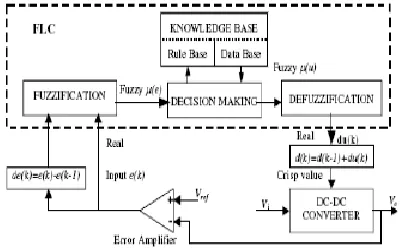
Fig.11. Block diagram of the Fuzzy Logic Controller (FLC) for dc-dc converters
A. Fuzzy Logic Membership Functions:
The dc-dc converter is a nonlinear function of the duty cycle because of the small signal model and its control method was applied to the control o f boost converters. Fuzzy controllers do not require an exact mathematical model. Instead, they are designed based on general knowledge of the plant. Fuzzy controllers are designed to adapt to varying operating points. Fuzzy Logic Controller is designed to control the output of boost dc-dc converter using Mamdani style fuzzy inference system. Two input variables, error (e) and change of error (de) are used in this fuzzy logic system. The single output variable (u) is duty cycle of PWM output.
T he Membership Function plots of error
T he Membership Function plots of change error
the Membership Function plots of duty ratio
B. Fuzzy Logic Rules:
The objective of this dissertation is to control the output voltage of the boost converter. The error and change of error of the output voltage will be the inputs of fuzzy logic controller. These 2 inputs are divided into five groups; NB: Negative Big, NS: Negative Small, ZO: Zero Area, PS: Positive s mall and PB: Positive Big and its parameter [10]. These fuzzy control rules for error and change of error can be referred in the table that is shown in Tab le I as per below:
V.M A TLA B/SIM ULINK RESULTS
Fig 13 T hree phase voltage of the microgrid in the voltage control mode with adding six-pulse rectifier to load at O. 08
Fig 14 Three phase current of the microgrid(top figure) and utility grid(lower figure) in the voltage mode control with
add mg six-pulse rectifier to load at t=0. 08
Fig 15 DC-bus voltage in the voltage mode control with adding six pulse rectifier at t=O. 08.
Fig 16 T hree phase voltage of the microgrid in the voltage control mode with adding single phase load at t=0. 08.
Fig 17 T hree phase current of the microgrid (top figure) and utility grid (lower figure) in the voltage mode control with adding single
phase load at t=O. 08.
Fig 18DC-bus voltage in the voltage mode control with adding six pulse rectifier at t=O. 08.
Fig 19Modeling of the system used for controlling of the DC-link voltage with fuzzy logic
Fig 20 simulation wave form of t hree phase voltage of the microgrid in the voltage control mode with adding single phase
load at t=0. 08 with fuzzy logic controller
Fig 21 T hree phase current of the microgrid (top figure) and utility grid (lower figure) in the voltage mode control with adding single
phase load at t=O. 08 with fuzzy logic controller
Fig 22 18DC-bus voltage in the voltage mode control with adding six pulse rectifier at t=O.08 with fuzzy logic controller
CONCLUSION
mode, i.e. Vo ltage control with fuzzy logic controller mode although the grid has a role in the control of both the power flow and voltage of the microgrid, it is slightly affected by the disturbances in the microgrid system.
REFERENCES
[I] R. Maju mder. A. Ghosh. G. Ledwich. and F. Zare. "Power management and power flo w control with back-to-back converters in a utility connected microgrid," IEEE Trans. Power Systems. , vol. 25, no. 2, pp. 0885-8950, May. 2010. [2] U. Nutkan i, P. C. Loh, and F. Blaabjerg, "Distributed operation of interlinked AC microgrids with dynamic active and reactive power tuning, " IEEE Trans. Ind. App. , vol. 49, no. 5, pp. 0093-9994, Sep/Oct. 2013.
[3] J. He, and Y. W. Li, " Generalized closed-loop control schemes with embedded virtual impedances for voltage source converters with LC or LCL filters, " IEEE Trans. Power. Electron. , vol. 2 7, no. 4, pp. 0885-8993, April. 2012. [4] M. Vilathgamu wa, A. A. D. Ranjith
Perera, and S. S. Choi, "Performance improvement of the dynamic voltage restorer with c1osed-loop load volt- age and current-mode control," IEEE Trans.
Power Electron. , vol. 17 , no. 5, pp. 824-834, Sep. 2002.
[5] F. Liu, S. Duan, J. Yin , B. Liu, and F. Liu, "Parameter design of a two current-loop controller used in a grid-connected inverter system with LCL filter," IEEE Trans. Ind. Electron. , vo l. 56, no. II, pp. 4483-4491, Nov. 2009.
[6] R. Teodorescu, F. Blaabjerg, U. Borup, M. Liserre, "A new control structure for grid-connected LCL PV inverters with zero steady-state error and selective harmonic compensation," IEEE 2004. [ 7] R. Teodorescu, M. Liserre, P. Rodriguez,
"Grid converters for photovoltaic and wind power systems," John Wiley & Sons, Ltd 2011.
[8] M. Hamzeh, H. Mokhtari, and H. Karimi, "A Decentralized Self-Ad justing Control Strategy for Reactive Po wer Management in an Islanded Mu lti-Bus MV Microgrid," Canadian Jou mal of Electrical and Co mputer Eng ineering, vol. 36, no. I , pp. 18-25, Winter 2013.
[9] M. Hamzeh, H. Karimi, and H.
Mokhtari, "Harmonic and
Negative-Sequence Current Control in an Islanded Multi-Bus M V Microgrid," IEEE Transactions on Smart Grid, vol. 5, no. I , pp. 167 -1 76, Jan. 2014.
A u thor’s Profile:
B. Sreenivas received B.TECH degree from Raja Mahendra College Engineering & Technology (JNTUH) in the year 2011 and received M.Tech in the stream of Electrical Power Engineering at Bharat Institute of Engineering &Technology(JNTUH).Currently working as a Assistant Professor in Scient Institute of Technology since 3 years and also the member of IJEEE. And his areas of interest are Power Systems, Electrical machines, Electrical Circuits and Control Systems.