A More Efficient AES Threshold Implementation
Beg¨ul Bilgin1,2, Benedikt Gierlichs1, Svetla Nikova1, Ventzislav Nikov3, and Vincent Rijmen1
1
KU Leuven, ESAT-COSIC and iMinds, Belgium{name.surname}@esat.kuleuven.be 2 University of Twente, EEMCS-DIES, The Netherlands
3
NXP Semiconductors, Belgium {name.surname}@nxp.com
Abstract. Threshold Implementations provide provable security against first-order power analysis attacks for hardware and software implementations. Like masking, the approach relies on secret sharing but it differs in the implementation of logic functions. AtEurocrypt
2011 Moradi et al. published the to date most compact Threshold Implementation of AES-128 encryption. Their work shows that the number of required random bits may be an additional evaluation criterion, next to area and speed. We present a new Threshold Implementation of AES-128 encryption that is 18% smaller, 7.5% faster and that requires 8% less random bits than the implementation fromEurocrypt2011. In addition, we provide results of a practical security evaluation based on real power traces in adversary-friendly conditions. They confirm the first-order attack resistance of our implementation and show good resistance against higher-order attacks.
Keywords: Threshold Implementation, First-order DPA, Glitches, Sharing, AES, S-box
1 Introduction
Related Work. The Threshold Implementation technique is based on a specific type of multi-party computation and applies boolean masking. Interesting properties of the technique are that it provides provable security against first-order side-channel attacks, that it requires few assumptions on the hardware leakage behavior, and that it allows to construct realistic-size circuits without intervention and design iterations. However, threshold implementations can still be broken by univariate mutual information analysis (MIA) [2,20] or univariate higher-order attacks [15].
It has been shown that all 3×3, 4×4 and the DES 6×4 S-boxes have a TI sharing with 3, 4 or 5 shares [5]. The TI approach has been applied to only few entire algorithms: PRESENT [21], AES [18] and Keccak [3]. In AES, the S-box is the by far most challenging part to share. Moradi et al. [18] have proposed a TI of this S-box that constantly uses 3 shares based on the tower field approach.
Contribution. We propose a more compact and faster Threshold Implementation of
AES-128 encryption that requires less random bits compared to the one by Moradi et al.
from Eurocrypt 2011. For the S-box we use the tower field approach overGF(24) and
for each block in the S-box computation we adapt the number of shares. This reduces the area by 13% and the clock cycles by 40%. However, our main focus is to optimize not only the S-box but the whole cipher. Our implementation of AES is 18% smaller, 7.5% faster and requires 8% less random bits than the implementation from Eurocrypt 2011. We
investigate the uniformity problem and the need for re-masking in more detail. We prove that under certain circumstances, it is enough to re-mask only a fraction of the shares. We evaluate the security of our implementation against first and higher-order attacks using real power traces in adversary-friendly conditions. The results confirm that it provides the theoretically guaranteed first-order attack resistance and show good security against higher-order attacks.
2 Threshold Implementation
TIs use sharings with the following properties: correctness, incompleteness and uniformity. The last property is often the most difficult to achieve, and the most costly in terms of hardware area. However, one can propose implementations where not every function satisfies the property of uniformity and fresh randomness is used instead to do a re-masking. In this section, we recall the TI properties and describe how circuit complexity can be traded off for fresh random bits.
2.1 Notation and Definitions
We denote by upper-case characters stochastic variables, and by lower-case characters the values they can take, i.e. elements of a finite field. LetX, taking values inFm, denote the input of the (unshared) functionf. Amaskingtakes as inputs a valuexand some auxiliary values (random masks), and outputs a vector (x1, x2, . . . , xsx) such that the XOR-sum of
thesx shares equals x. For all values x with Pr(X = x) >0, let Sh(x) denote the set of valid share vectors (x1, x2, . . . , xsx) for x:
Sh(x) ={(x1, x2, . . . , xsx)∈ F msx|x
1+x2+· · ·+xsx =x}.
Pr((X1, X2, . . . , Xsx) = (x1, x2, . . . , xsx)|X=x) denotes the probability that (X1, X2, . . . , Xsx) =
inputs of the masking. Similarly, we denote the output Y, taking values in Fn, and (y1, y2, . . . , ysy),Sh(y). LetF denote the vector function with input (X1, X2, . . . , Xsx) and
output (Y1, Y2, . . . , Ysy); we will call it a sharing. TIs, like most other masking schemes,
require that the masking isuniform, in the sense of the following definition.
Definition 1 (Uniform masking). A masking is uniform if and only if there exists a constant p such that for all x we have:
Pr((X1, X2, . . . , Xsx) = (x1, x2, . . . , xsx)|X =x) =p if (x1, x2, . . . , xsx)∈Sh(x),
else it is 0.
In words, we call a masking uniform if for each valuexof the variableX, the corresponding vectors with masked values occur with the same probability. Straightforward computation shows that this probabilityp= 2−m(sx−1).
Threshold implementations use sharings that satisfy the following properties. Firstly, the sharingF of f needs to be correct:
∀y ∈ Fn,∀(x1, x2, . . . , xsx)∈Sh(x),∀(y1, y2, . . . , ysy)∈Sh(y) : F(x1, x2, . . . , xsx) = (y1, y2, . . . , ysy)⇔f(x) =y.
Secondly, the sharing needs to beincomplete: every component function of F should be independent of at least one share Xi. The third property is uniformity of the sharing. Although the main point of this section is that also sharings which do not satisfy the third property can be used in threshold implementations, we provide the definition already now.
Definition 2 (Uniform sharing). The sharingF of f is uniform if and only if
∀x∈ Fm,∀y∈ Fn with f(x) =y,∀(y1, y2, . . . , ysy)∈Sh(y) :
(x1, x2, . . . , xsx)∈Sh(x)|F(x1, x2, . . . , xsx) = (y1, y2, . . . , ysy) =
2m(sx−1)
2n(sy−1) .
It follows that a uniform sharingF is invertible if and only if f is invertible.
2.2 Security from Correctness and Incompleteness
The security of threshold implementations against first-order side-channel attacks follows from two intuitively easy steps. If the masking is uniform and the sharingF is incomplete, then
1. any single component function of F does not get the information to determine the value of X (it does not know x), hence cannot leak any information on X, and 2. the expected value (average) of any leakage signal of an implementation of the sharing
F, be it instantaneous or summed over an arbitrary period of time, is constant.
2.3 Uniformity for the Cascaded and Parallel Functions
If the threshold implementation technique is used to protect cascaded functions, then extra measures need to be taken, such that the input for the next non-linear operation is again a uniform masking. A similar situation occurs when the threshold implementation technique is used to protect several functional blocks acting in parallel on (partially) the same inputs. This occurs for example in implementations of the AES S-box using the tower field approach. If no special care is taken, then “local uniformity” of the distributions of the inputs of the individual blocks will not lead to “global uniformity”, i.e. for the joint distributions of the inputs of all blocks. For example, let f, g be two functions acting on the same inputX. Then, even ifF, Gare uniform sharings, producing uniformY =F(X) andY0=G(X), this does not imply that (Y, Y0) is uniform. Like with cascaded functions, if each of the parallel blocks satisfies the properties of correctness and incompleteness, there will be no leakage of signals within the parallel blocks, but the lack of uniformity in the joint distribution of the masking of the outputs can lead to information leakage if the outputs are combined as inputs to a next function.
We can take different types of actions to remedy this problem. We discuss here two alternatives. Thefirst approachis to require uniformity of the sharingF (Definition 2). We can show that if the sharing is uniform and the masking of its input is uniform, then also the masking of its output is uniform. Hence there will be no leakage in further functions, provided that their sharings are correct and incomplete.
Theorem 1. If the masking of X is uniform and the sharing F is uniform, then the
masking ofY =f(X), defined by(y1, y2, . . . , ysy) =F(x1, x2, . . . , xsx), is uniform.
The proof is omitted here to save space. Practice shows that adding the uniformity re-quirement to a sharing tends to blow up the mathematical complexity of the sharing, as well as the cost of implementation. In some applications, it might be better to consider an alternative remedy: re-masking as for example done by Moradi et al. [18]. Indeed, by adding new random masks to the shares, we can make the distribution uniform.
2.4 Reducing the Randomness Used in a Re-masking Step
The following theorem allows to reduce the amount of random bits used by re-masking steps of threshold implementations: under certain circumstances, only a fraction of the shares needs to be re-masked.
Theorem 2. Let Xbe a Q-ary variable and let(X1, X2, . . . , Xs) be a sharing ofX, where Pr(X1 = x1, X2 =x2, . . . , Xs =xs|X 6=x1+x2+· · ·xs) = 0 and Pr(X1 =x1, . . . , Xt =
xt) =Q−t,∀(x1, . . . , xt) for some t with1≤t≤s. Then the sharing (Y1, . . . , Ys), defined
by Yi = Xi for 1 ≤ i ≤t and Yi = Xi+Ri for t < i ≤ s, is a uniform sharing for X,
i.e.:Pr(Y1 =y1, Y2 =y2, . . . , Ys =ys|X =y1+y2+· · ·ys) =Q1−s, provided that the Ri,
i= t+ 1, . . . , s−1 are independently and uniformly distributed random Q-ary variables
and that Rs=−(Rt+1+· · ·+Rs−1).
Proof. We give here a sketch of the proof. We have:
Pr(Y1=y1, . . . , Ys=ys|X =y1+y2+· · ·ys)
= Pr(Y1=y1, . . . , Yt=yt|X=y1+y2+· · ·ys) (1)
SinceYi =Xi for 1≤i≤t, the first factor equalsQ−t. For the second factor we recall the definition ofYt+1to obtain that:
Pr(Yt+1=yt+1) =
X
xt+1
Pr(Xt+1 =xt+1) Pr(Rt+1 =yt+1−xt+1)
| {z }
Q−1
.
The same holds forYt+2, . . . , Ys−1 and since theRi have independent distributions, we can equate the second factor of (1) to:
Q1−s−t X
xt+1,...,xs−1
Pr(Xt+1 =xt+1, . . . , Xs−1=xs−1, Ys =ys|X =y1+· · ·+ys, X1 =x1, . . . , Xt=xt).
Recalling the definition ofYs completes the proof. ut
Clearly, the extra randomness required by the re-masking approach in some cases may be a worse problem than the blow-up in gate count caused by the uniform sharing approach. The point that we want to stress here, however is the following.
Observation 1 An implementation that uses re-masking, does not need uniform sharings in order to resist first-order attacks.
By relinquishing the uniformity requirement, it is often possible to reduce the number of shares and the size of the implementation. This will be used in the next section in order to reduce the number of shares in the subblocks of the AES S-box and improve on the implementation of [18].
3 Implementations
In this section, we will discuss the new TI of AES in detail. We will first describe the general data flow of our implementation. Then we will introduce a new approach to apply the TI to the S-box of AES which is the only non-linear layer of the block cipher. We used ModelSim to verify the functionality of the proposed design and Synopsys Design Vision D-201-.03-SP4 with Faraday Standard Cell Library FSA0A C Generic Core, which is based on UMC 0.18µm GenericII Logic Process with 1.8V voltage, for synthesis. We will conclude this section by providing the performance of our design together with the comparison with the previous work in [18].
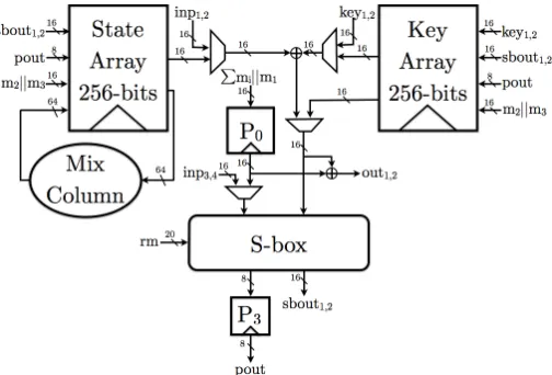
3.1 General Data Flow
Our main goal in this implementation is to minimize the area and randomness overhead caused by the sharing for a more efficient implementation. To achieve this, we use a serial implementation as proposed in [18] which requires only one S-box instance and loads the plaintext and key byte-wise in column-wise order. Moreover, we adapt the number of shares used in each operation in the block cipher. That is, we use two shares which is the minimum number of shares possible for all the affine operations such as MixColumns or Key XOR and increase or decrease the number of shares when required for the non-linear layer. This can also be seen in Fig. 7 in Appendix A, as the key and the state registers are 256 bits implying the two shares. With this approach we already decrease a significant part of the register cost since one bit register costs 5.33 GE in our library.
sbin1,2
sbin3,4
||m1
P
mi sig1 m2||m3
sig2 mcini sbout1,2 sbout3 mcouti S00
S01 S02 S03
S11 S12 S13
S10
S21 S22 S23
S20
S31 S32 S33
S30
P0
P3
(a) State array with ShiftRows
sbin1,2
sig3
sbout1,2
sbout3
K00 K01 K02 K03
K11 K12 K13 K10
K21 K22 K23 K20
K31 K32 K33 K30 P0 P3 ||m1 P mi
m2||m3
sig4 sig5 sbin3,4 sig6 rcon rndkeyi rndkeyi
(b) Key array
Fig. 1: Architecture of the registers.
sharing for the plaintext is also with four shares. The key is XORed to two of these shares before the S-box operation. After three clock cycles two of the output shares are written to the state register whereas one share is written to the register P3. The data in P3 is
merged with one of the shares after one clock cycle to be able to continue with two shares for the linear operations. In the following rounds, we increase the number of shares from two to four by using 24 bits of randomness one clock cycle before the S-box operation. We use P0 to store these extra two shares to achieve the non-completeness property of a
proper TI. The registers P0 and P3 are used both for the round transformations and the
key scheduling.
State Array (Fig. 1a) The state array consists of sixteen 16-bit registers each corre-sponding to the two shares of a byte in the state. From the first to the sixteenth clock cycle, the four input shares (first round) or the shares in the registers S00 and P0 (later
rounds) are sent to the S-box module. The corresponding three output shares are writ-ten to the registers S33 and P3 and shifted to the left horizontally from the third to the
eighteenth clock cycle. The signal sig2 is active from the fourth to the nineteenth clock cycle. The Shift Rows operation is also completed in the nineteenth clock cycle with an irregular horizontal shift. In the next four clock-cycles, the data in the registers S00, S10,
S20and S30 are sent to MixColumns operation, the rest of the registers are shifted to the
left horizontally and the output of the MixColumns operation is written to the registers S03, S13, S23 and S33. The MixColumns operation is implemented column-wise as in [18]
and with two shares working in parallel. The registers except S10, S11 and S12 are
imple-mented as scan flip-flops (SFF) that are D-flip-flops (DFF) combined with 2-to-1 MUXes and can operate with two inputs to reduce the area since a single 2-to-1 MUX costs 3.33 GE in our library whereas one bit SFF costs 6.33 GE. One round of AES takes 23 clock cycles. The signal sig1 is active for sixteen clock cycles, starting from the last clock-cycle of each round, for re-sharing.
Key Array (Fig. 1b) Similar to the state array, the key array also consists of sixteen 16-bit registers implemented as SFFs each corresponding to the two shares of a byte in the key schedule. The round key is inserted from the register K33in the first sixteen clock
cycles of each round. For the next three clock cycles, the registers except K03, K13, K23and
clock cycle. In that clock cycle, we increase the number of shares in the register K13. In
the following three clock cycles this re-sharing is done during the vertical shift from the register K23 to K13. Hence the re-sharing signal sig4 is active from the seventeenth to the
twentieth clock cycle. Signal sig5 is active from eighteenth to twenty first clock cycle to
reduce the number of shares. The registers K03, K13, K23 and K33 are not clocked in the
remaining two clock cycles of each round. We choose this way of irregular clocking to avoid using extra MUXes in our design. The S-box output is XORed to the data in K00together
with the round counterrconin the last four clock cycles of each round.rconis active only in the twentieth clock cycle and the number of shares are reduced in the output of the register K30. Signalsig3 is active in the first sixteen clock cycles except the fourth, eighth,
twelfth and sixteenth clock cycles. The roundkey is taken from the register K00.
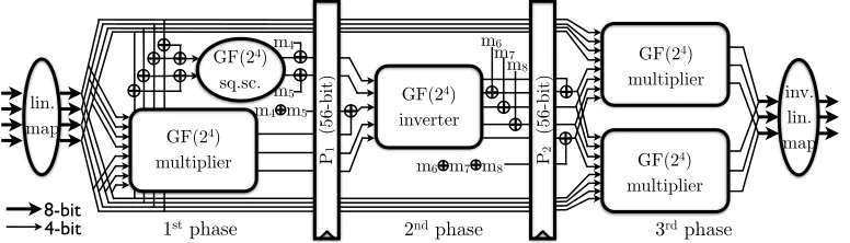
3.2 TI of the AES S-box
The S-box (Fig. 2) is shared between the key schedule and the state update. In the first sixteen clock cycles, it gets its inputs from the state. The input is taken from the key array in clock cycles eighteen to twenty-one.
lin. map
GF(24)
sq.sc.
GF(24)
multiplier m4
m5
m4 m5
P1
(56-bit)
GF(24)
inverter P2 (56-bit) m6 m7 m8
m6 m7 m8
GF(24)
multiplier
GF(24)
multiplier
inv. lin. map
1st phase 2nd phase 3rd phase
8-bit 4-bit
Fig. 2: The Sbox of our implementation.
The S-box implementation in [18], which can be observed in Appendix B, uses the tower field approach up toGF(22) for a smaller implementation. Therefore, the only non-linear operation isGF(22) multiplication which must be followed by registers to avoid first order leakages.
We also chose to use the tower field approach, however, we decided to go to GF(24) instead of GF(22). With this approach, the GF(24) inverter can be seen as a four bit permutation and theGF(24) multiplier as a four bit multiplication both of which are well studied in [4]. Therefore, we can find uniform TIs for these non-linear blocks directly which implies using less fresh random bits. Moreover, with this approach the S-box calculation takes three clock cycles instead of five.
The multiplier in GF(24) is a combination of three multipliers in GF(22) and some XOR gates as given in [7,18]. The algebraic normal form of this multiplier is given in Appendix C.1. This multiplication can be shared uniformly as in Appendix C.3 with four input and three output shares and the required area is 625 GE without any optimization. The GF(24) inverter, on the other hand, is a combination of three GF(22) multipli-cations, oneGF(22) inversion and some XOR gates (formula in Appendix C.2). To have a uniform sharing for this function, which belongs to class C4
282 [5], we consider two
uniform implementation in that class and decomposing the function into three uniform sub-functions asInv(x) =F(G(H(x))), or using five shares without any decomposition. Our experiments show that both versions have similar area requirements but a different number of clock cycles. To reduce the number of cycles, we chose the version with five shares, with the formula in Appendix C.4, which requires 618 GE. The sharing for this module is found by using the method described in [20] which is slightly different from the direct sharing [5]. We chose this formula since it can be implemented with less logic gates in hardware compared to the direct sharing.
Even though it is enough to use only two shares for linear operations, we sometimes chose to work on more than two shares to avoid the need for extra random bits. The linear map operates on four shares since the multiplication needs four input shares. The inverter requires five input shares and the multiplication outputs only three shares, therefore we use two shares for the square scalar to have five shares in the beginning of the second phase. We use three shares for the inverse linear map since the multiplication outputs three shares.
Combining the sub-blocks. During this process we face two challenges. One is to keep the uniformity in the pipeline registers as the sub-blocks are combined. That is a challenge Moradi et al. also faced and solved with re-masking. We also apply re-masking in the 2nd phase where we combine the 2 output shares of the square scaler and the 3 output shares of the multiplier to 5 shares. We must note that this combination also acts as the XOR of the output of the square scaler and multiplier in the unshared case. By theorem 2, it is enough to re-mask the output shares only for one function to achieve uniformity. We choose to re-mask the output of the square scaler since it operates on less shares hence requires less random bits. The correction mask, i.e. XOR of the masks, is XORed to one of the output shares of the multiplier to achieve correctness and non-completeness.
The second challenge is to keep the uniformity as we increase or decrease the number of shares. This is achieved by introducing new masks before the S-box operation to increase from two to four shares and at the end of the second phase to decrease from five to four shares. The output of the third phase together with the decrease from three to two shares is not uniform. However, uniform input is important for the non-linear functions only and the re-sharing before the S-box makes the input uniform.
We always keep the XOR of the masks in the pipeline registers and complete the re-masking in the next clock cycle as in [18]. Overall, we need 44 bits of fresh random numbers per S-box operation which is less than what was required in [18].
3.3 Performance
Table 1: Synthesis results for different versions of AES TI.
State Key
S-boxMixColContr.1 Key MUX Other Total cyclesrand
Array Array Col XOR bits2
[18] 2529 2526 4244 1120 166 64 376 89 11114/110313 266 48 This paper 1698 1890 3708 770 221 48 746 21 9102 246 44 This paper3 1698 1890 3003 544 221 48 746 21 8171 246 44 1 including round constant 2 per S-box 3compile ultra
registers P0 and P3 are also counted in the cost of the S-box together with the pipelined
registers P1 and P2.
In this implementation, the S-box occupies 40% of the total area. When compared to the previous implementation by Moradi et al., the S-box is 13% smaller and the overall area is 18% smaller. Moreover it is faster and requires less randomness. The numbers provided in Table 1 are taken from the Synopsys tool with compile command. We use these numbers for a fair quantitative comparison. On the other hand, it is also possible to compile each function that is provided in Appendix C.3 and C.4 individually with the
compile ultra command to let the tool optimize these functions and use the generated
optimized descriptions of these functions. This reduces the cost of TI of AES to 8171 GE. However, the results forcompile ultramainly reflect how good the tools are at optimizing and a comparison may not be fair.
4 Power Analysis
To evaluate the security of our design in practice we implement it on a SASEBO-G board [1] using Xilinx ISE version 10.1. We use the “keep hierarchy” constraint to prevent the tools from optimizing over module boundaries (see the last paragraph of Sect. 2.2). The board features two Xilinx Virtex-II Pro FPGA devices: we implement the TI AES and a PRNG on the crypto FPGA (xc2vp7) while the control FPGA (xc2vp30) handles I/O with the measurement PC and other equipment. The PRNG that generates all random bits is implemented as AES-128 in CTR mode.
We measure the power consumption of the crypto FPGA during the first 1.5 rounds of TI AES as the voltage drop over a 1Ωresistor in the FPGA core GND line. The output of the passive probe is sampled with a Tektronix DPO 7254C digital oscilloscope at 1GS/s sampling rate.
Methodology. We define two main goals for our practical evaluation. First, we want to verify our implementation’s resistance against first-order attacks. Second, we want to assess the level of security our implementation provides against other, e.g. higher-order, power analysis attacks.
Since there is no single, all-embracing test to evaluate the security of an implementa-tion, we follow the approach of [18] and test its resistance against state-of-the-art attacks. We narrow the evaluation to univariate attacks because our implementation processes all shares of a value in parallel. Estimating the information-theoretic metric by Standaert et al. [25] is out of reach. It would require estimation of up to 256 Gaussian templates.
FPGA with a stable 3MHz clock frequency to ensure that the traces are well aligned and the power peaks of adjacent clock cycles do not overlap (this would also help to assign a possibly identified leak to a specific clock cycle). In practice, clocking the device at a faster or unstable clock will make attacks harder. Note that the “combining effect” of the measurement setup or a faster clock described in [16] does not apply to our situation. In our implementation all shares are processed and leak at the same time, in contrast to the implementation analyzed in [16] where all shares are processed and leak separated in time. Hence we expect the effect to not ease an attack. Third, we let the adversary know the implementation. Specifically, if the PRNG was switched off the adversary would be able to correctly compute bit values and bit flips under the correct key hypothesis. In practice, obscurity is often used as an additional layer of security. Fourth, we use techniques described in [13] to achieve the best possible alignment of the traces.
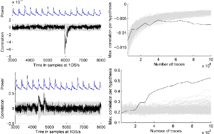
PRNG switched off. To confirm that our setup works correctly and to get some reference values we first attack the implementation with the PRNG switched off. We expect that the implementation can be broken with many first-order attacks. As example, Fig. 3 shows the result of a correlation DPA attack [6] that uses the Hamming distance of two consecutive S-box outputs as power model. The attacks require 2·28 key hypotheses. To reduce the computational complexity we let the adversary know one key byte and aim to recover the second one.
Fig. 3: Results of DPA attacks using HD model over 3/2/1 registers with PRNG off; left: correlation traces for all key hypotheses computed using 50 000 power traces, correct hypothesis in black, and a scaled power trace; right: max. correlation coefficient per key hypothesis (from the overall time span) over number of traces used.
Since the adversary knows the implementation, he can choose to compute the Hamming distance over three 8-bit registers (S33 and P3; output of the S-box in three shares), two
8-bit registers (S32; one cycle later; two shares) or ignore the details and compute the
distance over a single 8-bit register as if it was a plain implementation. The results for all three options are identical. This is a property of our implementation that vanishes when the PRNG is switched on. Only a few hundred traces are required to recover the key with one of these attacks. It is worth noticing that the highest correlation peak does not occur at the S-box output registers, but three resp. two clock cycles later when the bit-flips occur in register S30. This register drives the MixColumns logic and therefore has a much
greater fanout.
linear difference between the two key bytes involved. To do so, it permutes one set of mean traces according to a hypothesis on the linear difference and then correlates both sets of mean traces. The result shows that this attack is successful with a few thousand measurements.
Fig. 4: Result of a correlation collision attack with PRNG off; left: correlation traces for all hypotheses on the linear difference computed using 50 000 power traces, correct hypothesis in black, and a scaled power trace; right: max. correlation coefficient per hypothesis on the linear difference (from the overall time span) over number of traces used.
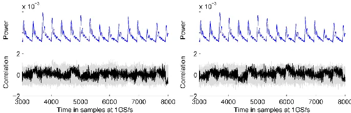
PRNG switched on. Next we repeat the evaluation with the PRNG switched on. Fig. 5 and Fig. 9 in Appendix D show the results of the first-order attacks against the protected implementation using 10 million measurements. The results show that the attacks fail.
Fig. 5: Results of first-order DPA and correlation collision attacks with PRNG on computed using 10 million traces; left: HD over 1 register, right: correlation collision.
We proceed with higher-order attacks to assess the level of security our implementation provides. For our second-order DPA attacks we use the same power models as before but center and then square the traces (for each time sample) before correlating [8,23,26]. Second-order correlation collision attacks work as above with mean traces replaced by variance traces [15].
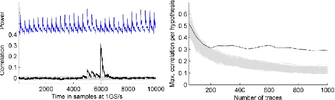
Fig. 6 (top) shows the results of the second-order DPA attack that uses the Hamming distance in a single register as power model (as if it was a plain implementation). The attack requires about 600 000 traces to succeed. We note that the highest correlation peak occurs again when the bitflips happen in register S30, cf. Fig. 3. Second-order DPA attacks
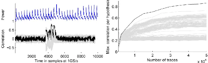
Fig. 6 (bottom) shows the results of the second-order correlation collision attack. The attack requires about 3.5 million traces to succeed. A third-order correlation collision attack works as above with mean traces replaced by skewness traces [15]. This attack fails using 10 million measurements.
Fig. 6: Results of second-order DPA (top) and correlation collision (bottom) attacks with PRNG on computed using 10 million traces; right: min./max. correlation coefficient per hypothesis (from the overall time span) over number of traces used.
Discussion. The first goal of our evaluation is to verify our implementation’s resistance against first-order attacks. But this goal is always limited by the number of measurements at hand. It is simply not possible to demonstrate resistance against attacks with an infinite number of traces. However, we argue that for practical security a different criterion is more relevant: a first-order attack must not be the easiest attack vector. In other words, the job is done if a non-first-order attack becomes easier than a first-order attack. The second goal is to assess the level of security our implementation provides against such other attacks.
We have shown that our implementation resists state-of-the-art first-order attacks with 10 million traces in conditions that are strongly in favor of the adversary (no algorithmic noise from the PRNG, knowledge of the implementation, slow and stable clock, best pos-sible alignment). In the same conditions, the most trace-efficient second-order attack in our evaluation requires about 600 000 traces.
It is tempting to compare the results of our evaluation to the results of the evaluation in [18]. However, not only the implementations but also the measurement platforms and the conditions differ, so that any difference must not be credited to an implementation alone. Already the numbers of traces required for attacks against the implementations with PRNG switched off differ by roughly two orders of magnitude. In addition, the analysis in [18] is limited to four clock cycles during the S-box computation.
5 Acknowledgement
This work has been supported in part by the Research Council of KU Leuven (OT/13/071), B. Bilgin was partially supported by the FWO project G0B4213N, V. Nikov was supported by the European Commission (FP7) within the Tamper Resistant Sensor Node (TAM-PRES) project with contract number 258754 and Benedikt Gierlichs is a Postdoctoral Fellow of the Research Foundation - Flanders (FWO).
References
1. AIST. Side-channel Attack Standard Evaluation BOard. http://staff.aist.go.jp/akashi.satoh/ SASEBO/en/.
2. L. Batina, B. Gierlichs, E. Prouff, M. Rivain, F.-X. Standaert, and N. Veyrat-Charvillon. Mutual Information Analysis: a Comprehensive Study. J. Cryptol., 24(2):269–291, April 2011.
3. G. Bertoni, J. Daemen, M. Peeters, and G. Van Assche. Building power analysis resistant implemen-tations ofKeccak. Second SHA-3 candidate conference, August 2010.
4. B. Bilgin, S. Nikova, V. Nikov, V. Rijmen, and G. St¨utz. Threshold implementations of all 3×3 and 4×4 S-boxes. Cryptology ePrint Archive,http://eprint.iacr.org/.
5. B. Bilgin, S. Nikova, V. Nikov, V. Rijmen, and G. St¨utz. Threshold implementations of all 3×3 and 4×4 S-boxes. InCHES, volume 7428 ofLNCS, pages 76–91. Springer, 2012.
6. E. Brier, C. Clavier, and F. Olivier. Correlation power analysis with a leakage model. In CHES, volume 3156 ofLNCS, pages 16–29. Springer, 2004.
7. D. Canright. A very compact S-box for AES. InCHES, volume 3659 ofLNCS, pages 441–455. Springer, 2005.
8. S. Chari, C. S. Jutla, J. R. Rao, and P. Rohatgi. Towards sound approaches to counteract power-analysis attacks. InCRYPTO, volume 1666 ofLNCS, pages 398–412. Springer, 1999.
9. L. Goubin and J. Patarin. DES and differential power analysis the “duplication” method. InCHES, volume 1717 ofLNCS, pages 158–172. Springer, 1999.
10. P. C. Kocher, J. Jaffe, and B. Jun. Differential power analysis. InCRYPTO, volume 1666 ofLNCS, pages 388–397. Springer, 1999.
11. S. Mangard, T. Popp, and B. M. Gammel. Side-channel leakage of masked CMOS gates. InCT-RSA, volume 3376 ofLNCS, pages 351–365. Springer, 2005.
12. S. Mangard, N. Pramstaller, and E. Oswald. Successfully attacking masked AES hardware implemen-tations. InCHES, volume 3659 ofLNCS, pages 157–171. Springer, 2005.
13. T. S. Messerges.Power analysis attacks and countermeasures on cryptographic algorithms. PhD thesis, University of Illinois at Chicago, 2000.
14. T. S. Messerges. Securing the AES finalists against power analysis attacks. In Bruce Schneier, editor,
FSE, volume 1978 ofLNCS, pages 150–164. Springer, 2000.
15. A. Moradi. Statistical tools flavor side-channel collision attacks. In D. Pointcheval and T. Johansson, editors,EUROCRYPT, volume 7237 ofLNCS, pages 428–445. Springer, 2012.
16. A. Moradi and O. Mischke. On the simplicity of converting leakages from multivariate to univariate - (case study of a glitch-resistant masking scheme). In G. Bertoni and J.-S. Coron, editors, CHES, volume 8086 ofLNCS, pages 1–20. Springer, 2013.
17. A. Moradi, O. Mischke, and T. Eisenbarth. Correlation-enhanced power analysis collision attack. In
CHES, volume 6225 ofLNCS, pages 125–139. Springer, 2010.
19. S. Nikova, C. Rechberger, and V. Rijmen. Threshold implementations against side-channel attacks and glitches. InICICS, volume 4307 ofLNCS, pages 529–545. Springer, 2006.
20. S. Nikova, V. Rijmen, and M. Schl¨affer. Secure hardware implementation of nonlinear functions in the presence of glitches. J. Cryptology, 24(2):292–321, 2011.
21. A. Poschmann, A. Moradi, K. Khoo, C.-W. Lim, H. Wang, and S. Ling. Side-channel resistant crypto for less than 2300 GE. J. Cryptology, 24(2):322–345, 2011.
22. E. Prouff and M. Rivain. Masking against side-channel attacks: A formal security proof. In Thomas Johansson and Phong Q. Nguyen, editors, EUROCRYPT, volume 7881 of LNCS, pages 142–159. Springer, 2013.
23. E. Prouff, M. Rivain, and R. Bevan. Statistical analysis of second order differential power analysis.
IEEE Trans. Computers, 58(6):799–811, 2009.
24. E. Prouff and T. Roche. Higher-order glitches free implementation of the AES using secure multi-party computation protocols. InCHES, volume 6917 ofLNCS, pages 63–78. Springer, 2011.
25. F.-X. Standaert, T. Malkin, and M. Yung. A unified framework for the analysis of side-channel key recovery attacks. In Antoine Joux, editor, EUROCRYPT, volume 5479 of LNCS, pages 443–461. Springer, 2009.
26. J. Waddle and D. Wagner. Towards efficient second-order power analysis. In M. Joye and J.-J. Quisquater, editors,CHES, volume 3156 ofLNCS, pages 1–15. Springer.
A Architecture of the serialized TI of AES-128
Fig. 7: Architecture of the serialized TI of AES-128 .
B Architecture of the AES S-box described in [18]
C Equations
C.1 Multiplier in GF(24)
(f1, f2, f3, f4) = (x1, x2, x3, x4)×(x5, x6, x7, x8)
f1 =x1x5⊕x3x5⊕x4x5⊕x2x6⊕x3x6⊕x1x7⊕x2x7⊕x3x7⊕x4x7⊕x1x8⊕x3x8
f2 =x2x5⊕x3x5⊕x1x6⊕x2x6⊕x4x6⊕x1x7⊕x3x7⊕x2x8⊕x4x8
f3 =x1x5⊕x2x5⊕x3x5⊕x4x5⊕x1x6⊕x3x6⊕x1x7⊕x2x7⊕x3x7⊕x1x8⊕x4x8
Fig. 8: Architecture of the AES S-box described in [18] .
C.2 Inverter inGF(24)
(f1, f2, f3, f4) =Inv(x1, x2, x3, x4)
f1 =x3⊕x4⊕x1x3⊕x2x3⊕x2x3x4
f2 =x4⊕x1x3⊕x2x3⊕x2x4⊕x1x3x4
f3 =x1⊕x2⊕x1x3⊕x1x4⊕x2x2x4
f4 =x2⊕x1x3⊕x1x4⊕x2x4⊕x1x2x3
C.3 Sharing Multiplier inGF(24) with 4 Input 3 Output Shares
f =xy, where
f =f1⊕f2⊕f3
x=x1⊕x2⊕x3⊕x4
y=y1⊕y2⊕y3⊕y4
f1 = (x2⊕x3⊕x4)(y2⊕y3)⊕y4
f2 = ((x1⊕x3)(y1⊕y4))⊕x1y3⊕x4
f3 = ((x2⊕x4)(y1⊕y4))⊕x1y2⊕x4⊕y4
C.4 Sharing Inverter in GF(24) with 5 Input 5 Output Shares
f =xyz⊕xy⊕z, where
f =f1⊕f2⊕f3⊕f4
x=x1⊕x2⊕x3⊕x4⊕x5
y=y1⊕y2⊕y3⊕y4⊕y5
f1 = ((x2⊕x3⊕x4⊕x5)(y2⊕y3⊕y4⊕y5)(z2⊕z3⊕z4⊕z5))
⊕((x2⊕x3⊕x4⊕x5)(y2⊕y3⊕y4⊕y5))⊕z2
f2 = (x1(y3⊕y4⊕y5)(z3⊕z4⊕z5)⊕y1(x3⊕x4⊕x5)(z3⊕z4⊕z5)
⊕z1(x3⊕x4⊕x5)(y3⊕y4⊕y5)⊕x1y1(z3⊕z4⊕z5)⊕x1z1(y3⊕y4⊕y5)
⊕y1z1(x3⊕x4⊕x5)⊕x1y1z1)⊕(x1(y3⊕y4⊕y5)⊕y1(x3⊕x4⊕x5)⊕x1y1)⊕z3
f3 = (x1y1z2⊕x1y2z1⊕x2y1x1⊕x1y2z2⊕x2y1z2⊕x2y2z1⊕x1y2z4⊕x2y1z4⊕x1y4z2
⊕x2y4z1⊕x4y1z2⊕x4y2z1⊕x1y2z5⊕x2y1z5⊕x1y5z2⊕x2y5z1⊕x5y1z2⊕x5y2z1)
⊕(x1y2⊕y1x2)⊕z4
f4 = (x1y2z3⊕x1y3z2⊕x2y1z3⊕x2y3z1⊕x3y1z2⊕x3y2z1)⊕0⊕z5
D Plots of Power Analysis Attacks


![Fig. 8: Architecture of the AES S-box described in [18] .](https://thumb-us.123doks.com/thumbv2/123dok_us/7899356.1311236/15.612.152.480.75.167/fig-architecture-aes-s-box-described.webp)