Performance of BER Analysis of MIMO
System using BPSK Modulation under
Different Channel with STBC, ML and MRC
Krishna Kant Dubey1, D.K. Srivastava2
P.G. Student, Department of Electronics and Communication Engineering, B.I.E.T Jhansi, U.P, India1
Associate Professor, Department of Electronics and Communication Engineering, B.I.E.T Jhansi, U.P, India2
ABSTRACT: Higher data rate and easier communication is required for commercial wireless communication system. System design in the multipath fading is channelled in wireless communication system because which gives weak signal strength and enhance the bit error rate of communication system. Multi input- multi output (MIMO) system is used to overcome this drawback. Multiple antennas are used to gives higher data rate, higher transmit and receive diversity through spatial multiplexing in wireless communication system. This paper presents a detail study of bit error rate(BER) analysis of multi input- multi output(MIMO) system under AWGN(additive white Gaussian noise) and Rayleigh fading communication channel. It is used maximum like hood detector and maximal ratio combining at the receiver side and encoded by Almouti space time block code at the transmitter sides. Almouti space time block code (STBC) gives the transmit diversity. System result is observed by BPSK modulation technique using MATLAB. Simulation result gives the comparison between two channels, AWGN channel has better achievement.
KEYWORDS: MIMO, BER, AWGN, ML, Rayleigh, MRC
I. INTRODUCTION
By increasing the demand of high speed of multimedia wireless services is achieved by modern communication system. There are different type of aspect which decreases the performance of the communication system such as interference and noise, loss and propagation, limitation of bandwidth and fading due to multipath [1]. There are different type of antenna which is used at the transmitter and receiver section. To slash the fading and enhance the capacity with the help of spatial diversity or spatial multiplexing [1] .Multi input multi output is one of the most important techniques which is used in wireless system that desire high data rates and transmit diversity. There are different parameters such as selections of modulation technique, signal processing chains, and supplementary antennas are critical in multi input multi output system, it gives the restriction of antenna size mainly for mobile. Advantage of MIMO technique depends on multiplicity of receiver and coding scheme so in performance of wireless communication system multi input multi output play important role.[3].
In a now days, requirement of wireless machinery is very high STBC play important role for study purpose in various modulation technology. There are four procedures such as simulation of the Almouti STBC transmission system, digital transmission system, modelling and commutation and relation of bit error rate. [4]
In this paper, its evaluate bit error rate of MIMO system in AWGN and Rayleigh fading channel, where at the transmitter section Almouti STBC is used for encoding the information and the receiver side maximal ratio combining (MRC) and Maximum Likehood (ML) is used for decoding purpose. Modulation scheme BPSK is used for modulate the encoded signal. This paper qualified as followed in section II, the MIMO system model is described. Section III, encoder and decoder. In Section IV, modulation scheme. Section V, discuss the AWGN and Rayleigh fading channel. In Section VI, bit error is discussed. In Section VII, numerical results are obtained and Section VIII gives the final conclusion.
II. SYSTEM MODEL
There is suppose that a MIMO system transmit section consist of MT antenna and receive section consist of MR antenna
[5].Fig.1 shows the block diagram of MIMO system.
Figure1. Block Diagram of MIMO System
In transmitter section is the transmitted matrix S is column matrix. It is denoted by MT*1 where S, denotes the ith
component transmitted of transmit antenna. Alamouti STBC used in transmitted section, advantage of this STBC code channel state information is not required for transmit the data. It is used Gaussian channel the component S are independent identically distribution Gaussian variable. If the channel information not known the transmitter side then signal power transmitted of single antenna is equal to 𝑃𝑠
𝑀𝑇. Covariance matrix 𝑅𝑠𝑠 of transmitted signal can be written as equation (1)
𝑅𝑠𝑠= 𝑃𝑠
𝑀𝑇∗ 𝐼𝑀𝑇 (1)
Where Ps represents the total transmit power of transmitter and IMT represent the identity matrix. The channel matrix H
for MT transmit antenna and MR receive antenna is MR*MT complex matrix. Hij represent the component of channel
matrix H for jth transmit antenna and ith received antenna.[6] In receiver section the received matrix Y is column matrix. It is denoted by MR*1.It is consider that transmit and received power of transmitter and receiver section is equal than
the SNR can be written as in equation (2)
𝛾 = 𝑃𝑠
𝑁0 (2)
Where Ps and N0 represent signal and noise power.
III. ENCODER AND DECODER
A. Alamouti Space Time Block Code
The Alamouti STBC is a well known diversity technique which uses the information increase multiple antennas at the transmitter. The Alamouti STBC is basically provide transmits complex space-time diversity. It is used spread the information at the transmitter end. It is classified as two modes (2*1 MISO mode or 2*2 MIMO mode). It gives full diversity gain without need to loss its data rate. The advantage of Alamuoti STBC it gives better bit error rate as compared to oldest STBC [7].
Coding and interleaving
Symbol mapping
Space time encoding
Space time precoding
Space time processing Space time
decoding Symbol
mapping Deinterleaving
and decoding
1. 2*1 Alamouti STBC
Table 1: 2*1 Alamouti STBC
Time Transmitter 1 Transmitter 2 Time t X1 X2
Time t+T -X2 *
X1 *
Where X1 and X2 are the modulated signal. The received vector can be written as from Table 1
Y1 = h1(X1) + h2(X2) + n1 (first time slot) (3)
Y2 = h1(-X2*) + h2(X1*) + n2 (second time slot) (4)
Where:X1 and X2 modulated symbol, Y1 and Y2 Received vectors, h1 and h2 impulse response of Rayleigh channel ,n1 and n2 AWGN channel Equation (3) and equation (4) can be written in matrix equation from as 𝑌1 𝑌2 = 𝑋1 𝑋2 −𝑋2∗ 𝑋1∗ ℎ1 ℎ2 + 𝑛1 𝑛2 (5)
𝐻 = ℎ1ℎ ℎ2 2∗ −ℎ1∗ Where H is a 2*2 channel matrix, a* represents the complex conjugate of a Y=H X + N (6)
Where H is an orthogonal matrix (2) 2*2 Alamouti STBC 2*2 alamouti STBC 2 transmit and 2 receive antenna consist. Working principle same as 2*1 alamouti STBC but it consist one extra received antenna. It gives better bit error rate performance as compare to 2*1 alamouti STBC. We assume that the channel parameter remains constant during the two time slot. Y11 = h11(X1) + h12(X2) + n11
(first time slot receive data in RX1) (7)
Y12 = h21(X1) + h22(X2) + n12
(first time slot receive data in RX2) (8)
Y
2 1= h
11(-X
2*) + h
12(X
1*) + n
21 (second time slot receive data in RX1) (9)Y
2 2= h
21(-X
2*) + h
22(X
1*) + n
22 (second time slot receive data in RX2) (10)The received vector in second time slot is
𝑌21 𝑌22 =
ℎ11 ℎ12
ℎ21 ℎ22
−𝑋2∗ 𝑋1∗ +
𝑛21
𝑛22 (12)
Where X1 and X2 are modulated symbol,Y11 and Y12 are received vectors (first time slot),Y21 and Y22 are received
vectors (second time slot) ,h11, h12 , h21 and h22 are impulse response of Rayleigh fading channel,n11, n12 AWGN noise
(first time slot) ,n21 and n22 AWGN noise ( second time slot)
B.Maximum Likehood Decoder
For decoding of alamouti STBC there are different method like ZF (zero forcing), minimum mean square estimation (MMSE), Brut Force ML decoding etc. In above method Maximum Likehood decoding gives better performance. The ML receiver tries to find 𝑋 which minimize J =|Y-H𝑋 |2
for the BPSK modulation. The possible value of X1 is +1 and -1
and X2 is also lies between 1 and -1. So find the minimum value of J all four possible combinations in the ML decoder
for below equation (13)
𝐽 = | 𝑌𝑌1 2 −
ℎ11 ℎ12
ℎ21 ℎ22 𝑋1 𝑋 2 |
2 (13)
The estimate of the transmit symbol is chosen best on the minimum value from the above four values If the minimum is J+1,+1= [1 1], If the minimum is J+1,-1= [1 0], If the minimum is J-1,+1 = [0 1] and If the minimum J-1,-1= [0 0]
C .Maximal Ratio Combining
In telecommunication different method is use to combine the signal. MRC is as method of diversity combining. MRC multiplied the all branches signal. MRC amplified higher amplitude signal but shrink the low amplitude signals. It is also add the signal from each channel and gain of each channel is made directly proportional to the RMS signal value and inversely proportional to the mean square noise value in that channel. Each channel is different. It is known as RSC (ratio-squared-combining) and PC (prediction combining). MRC is also known as optimum combiner and it is independent of AWGN channels. It can achieved high bit error rate when MRC is used in multi input multi output receiver. The least square solution in this case is also known as maximal ratio combining. In the case of two antennas the least square solution can be written as equation (14)
𝑋 = ℎ1∗∗𝑌1+ℎ2∗𝑌2
|ℎ12|+|ℎ22| (14)
IV. MODULATION
If the digital modulation modulates the incoming data BPSK (Binary phase shift keying) modulation is used. Encoding of M massage bits single pulse transmit 2M possible time shifts. Transmit bit rate M/T (bit per second) is replicate after every T second. This paper BPSK modulation scheme is used.
V. COMMUNICATION CHANNEL
channel. The fast fading channel impulse response is changed while slow fading channel impulse response is constant from many symbols. This paper study the performance of bit error rate of MIMO system under AWGN and Rayleigh fading channel using Alamouti STBC encoders, ML and MRC receivers.
(A) AWGN
AWGN channel add White Gaussian noise when signal pass through it. Noise add in AWGN depends only what is the input signal is applied where the input is complex the add complex Gaussian noise and output is also complex in nature. When the inputs signal is used real output is also real and add real Gaussian noise. Gaussian means normal distribution in time domain with an average time domain value only. It is used only impairment to communication is a continuous addition of white band or white noise with stable spectral density and Gaussian distribution of amplitudes. Modulation signals pass through AWGN channel amplitude and phase distortion not loss only change in phase. This model does not tell for fading, frequency selectivity, interference and nonlinearity. Only distortion is introduced in equation (15) the received signal y (t) is simplified to equation (15)
Y(t) = X(t) + n(t) (15)
Where n(t) denotes AWGN Gaussian noise. The probability density function can be expressed as equation (16)
𝑃 𝑛 =1
2 2𝜋𝜎
2𝑒−(𝑛 −𝜇 )22𝜎 2 (16)
For AWGN channel 𝜇 = 0 where 𝜇 represents Gaussian means and𝜎2=𝑁0 2.
B. Rayleigh
Three main mechanism of electromagnetic wave propagation are reflection, diffraction and scattering. The Rayleigh fading model combination of scatter and reflected signal. It is used for modulation the signal of troposphere and ionosphere. A case approximation of attenuation due to multi path fading wireless channel can be done by Rayleigh fading channel. There are no line of sight communication consist between transmitter and receiver. Rayleigh distribution can also be GOT by taking two identically distributed zero mean Gaussian random variable as real and imaginary part of a complex number and then taking its magnitudes this is given in equation (17)
ℎ𝑖𝑗 = 1
2∗ ( 𝑛𝑜𝑟𝑚𝑎𝑙 0,1 + −1 Normal (0, 1)) (17)
Received signal of receiver side can also be written as equation (18)𝑅 𝑛 = ℎ 𝑛, 𝜏 ∗ 𝛿 𝑛 − 𝑚 + 𝑤(𝑛) (18)
Impulse response of zero mean and unit variance can be written as equation (19)
ℎ 𝑛 = 𝛼 𝑛 ∗ 𝑒−𝑗𝜃 (𝑛) (19)
Where 𝛼 𝑛 𝑎𝑛𝑑 𝜃(𝑛) attenuation and phase shift for nth path. Probability density function of Rayleigh can be written
as equation (20)
𝑓 𝑥 = 𝑥
𝜎2𝑒 −𝑥 2
VI. BIT ERROR RATE ANALYSIS: A. BER
BER is a metric which a can be implied to characterized the performance of communication system. Bit error rate is basically the average rate of bit error for particular communication
𝐵𝐸𝑅 = 𝑛𝑢𝑚𝑏𝑒𝑟 𝑜𝑓 𝑏𝑖𝑡 𝑖𝑛 𝑒𝑟𝑟𝑜𝑟
𝑇𝑜𝑡𝑎𝑙 𝑛𝑢𝑚𝑏𝑒𝑟 𝑜𝑓 𝑏𝑖𝑡 𝑡𝑟𝑎𝑛𝑠𝑚𝑖𝑡𝑡𝑒𝑑
Bit error rate is frequently expressed as of probability this is denoted by Pe (probability of bit error rate) the value of Pe
lies between 0 to 0.5.
B. SNR
It is the ratio of received signal power into noise power. It is inversely proportional to bit error rate.SNR is measured in decibel. It is used to measure the clarity of the signal in a wired and wireless communication. In the term of diversity SNR formula can be written as in equation (21)
𝐵𝐸𝑅 = 1
𝑆𝑁𝑅𝑑 (21)
C. Bit Error Rate of AWGN Channel
Probability of bit error rate in AWGN channel for BPSK modulation can be written as equation (22)
𝑃𝑏 = 𝑄
𝐸𝑏
𝑁0 = 𝑄( 𝑆𝑁𝑅) (22)
Approximate bit error rate analysis of AWGN channel can be written as equation (23)
𝑃𝑏 =1
2𝑒 −1
2𝑆𝑁𝑅 =1
2𝑒𝑟𝑓𝑐
𝐸𝑏
𝑁0 (23)
D. Bit Error Rate of Wireless Rayleigh Fading Channel
In wireless communication system the received signal power in Rayleigh fading channel is equal to |h|2PT.Where PT
denotes transmit power. SNR in Rayleigh fading channel can be written as equation (24)
𝑆𝑁𝑅𝐹= |ℎ|2∗ 𝑃
𝜎2= |ℎ|
2∗ 𝑆𝑁𝑅 (24) For bit
error rate derived from BPSK modulation in Rayleigh fading channel can be written as equation (25)
𝑃𝑏 =1
2(1 −
𝑆𝑁𝑅
2+𝑆𝑁𝑅) (26)
E. Average BER of Alamouti-STBC
Average BER Alamouti-STBC can be written as equation (27)
𝑃𝑏 = 𝐶(
1 𝑆𝑁𝑅)
𝐿 𝐿
2𝐿−1 (27)
Where L = r-t+1 where r represent number of received antenna and e represent number of transmit antenna.
F. BER OF MRC
The BER of MRC can be written as equation (28)
𝑷𝒃=𝟏 𝟐−
1
2(1 + 1
𝑆𝑁𝑅) 1
2 (28)
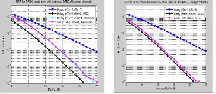
VII. SIMULATION RESULTS
In this section the bit error rate analysis of MIMO system done AWGN and Rayleigh fading channel and Alamouti SBTC code with ML, MRC receiver in this section BPSK modulation used.
Figure 2 shows the bit error rate value of 2*1 alamouti STBC with BPSK modulation using Rayleigh fading channel. 2*1 alamouti STBC BPSK modulation the value of bit error rate is 4.34*10^-4. We get SNR value of 20db.
Figure 3 shows the bit error rate value of 2*2 alamouti STBC with BPSK modulation using Rayleigh fading channel. The bit error rate value of 2*2 alamouti STBC is 1.1*10^-5 in 21 db SNR.
Figure.2 BER of 2*1 Alamouti STBC ML equalizer Figure.3 BER of 2*2 Alamouti STBC ML equalizer
Figure 4 shows the bit error rate value of 2*1 alamouti STBC with BPSK modulation using Rayleigh fading channel and AWGN channel. The bit error rate value of 10^-3 in 6.5db SNR. For AWGN channel and the bit error rate value of 10^-3 in 14 db SNR for Rayleigh fading channel.
Figure.5 BER of 2*2 Alamouti STBC ML equalizer Figure.4 BER of 2*1 Alamouti STBC ML equalizer
Rayleigh fading and AWGN channel Rayleigh fading and AWGN channel
Figure 5 shows the bit error rate value of 2*2 alamouti STBC with BPSK modulation using AWGN and Rayleigh fading channel. The bit error rate value of 10^-3 in 6.5db SNR for AWGN channel and the bit error rate value of 10^-3 in 12.5db SNR for Rayleigh fading channel. The performance of AWGN channel is better than Rayleigh channel because the bit error rate of AWGN channel is better than Rayleigh fading channel.
VIII. CONCLUSION
MIMO system performance is analyse BPSK modulation scheme in AWGN channel and Rayleigh channel. The bit error rate performance of AWGN channel is better compare to Rayleigh fading channel. In compare to the decoding technique ML decoder gives better bit error rate as compare to ZF and MMSE. The MIMO system MRC is the best equalization large bit error rate as compare to MRC but Alamouti STBC channel state information is not required. SNR of MRC is twice the SNR of Alamouti STBC. SNR is high its require large power at the transmitter side the performance of bit error rate also improve increase the number of transmit and receive antenna.
REFERENCES
[1] Tarokh V, Naguib A, Seshadri N and Calderbank, A. R, ‘’Combined Array Processing and Space-Time Coding,’’ IEEE Transaction on Information Theory, vol. 45, no. 4, 1999.
[2] N. Kumar & L. Kansal, ‘’Performance Comparison of MIMO System over AWGN and Rican Channel with Zero Forcing Receivers’’,
International Journal of Wireless & Mobile Network, VOL. 5, Issue 1, pp. 73-84, 2013. [3] A. S. Mindaudu and A. M. Miyim, ‘’BER Performance of MPSK and MQAM in 2*2 Alamouti MIMO System’’, International Journal of
Information Sciences and Techniques (IJIST) vol .2, No.5 September
[4] Robert Schober, Wolfgang H. Gerstacker, and Lutz H, J. Lampe, ‘’Performance Analysis and Design of STBC for Fading ISI Channel’’, mobile radio communication, IEEE 2002.
[5] G.J. Foschini and M. J. Gans, ‘’On Limits of wireless communication in a fading environment when using multiple antennas’’, Wireless Personal Communication, Mar. 1988, pp. 311-335.
[6] V. K. Garg and J. E. Wilkes,’’ Wireless and Personal Communication System’’, Prentice Hall, 1966
[7] Chunju .Gao,Alexander .M. Haimovich, Debang Lio, ‘’Beat Error probability for Space-Time Block Code with Coherent and Differential Detection’’, Communication and Signal Processing Research, IEEE 2002.
[9] Jitendra Kumar Daksh, Ravi Mohan and Shumit Sharma, ‘’Performance Analysis with Space-Time Coding in MIMO –OFDM System with Multiple Antenna’’, International Journal of Advanced Computer Research, vol 3, no. 5 June 2013.
[10] M. P. Chatra and Dr. S.K. Srivatsa, ‘’BER Analysis of Coded and Uncoded MIMO-OFDM System in Wireless Communication’’, Indian Journal of Computer Science and Engineering, vol.1, NO. 4, pp. 357-363.
[11] Paresh M. Dholakia, Dr. Sanjay Kumar, Dr. C. H. Vithlani and Mitesh Solanki, ‘’On Performance International Conference in Computing Technologies, pp. 1-7, IEEE 2014.
[12] Khaled Hijjeh, Anwar Abu Afeefeh, Linda Manasrah,Wala A. Sayed and Ameena Masri, ‘’Mat lab Simulation for Diversity in 8*2 MIMO System Using OSTBC, pp. 11-15, IEEE 2011.