Comparative Analysis of Mitigation
Techniques for Inrush Current of Transformer
Sneha Borse1, Prof. S.S. Mopari2
PG Student, Department of Electrical Engineering, Government College of Engineering, Aurangabad,
Maharashtra, India1
Associate Professor, Department of Electrical Engineering, Government College of Engineering, Aurangabad
Maharashtra, India2
ABSTRACT:Power transformers are key element for transfer electric energy at various stages in power system. Hence stability and security of power transform is very important task in power system. During energization, due to saturation of core high magnitude of transformer inrush currents generated which may climb to ten times of rated current, thus transient inrush current which is capable to produced serious power quality problem as well as mal-operation of protection system. Hence controlling and reduction methods in order to control transient current are essentially important to the engineers in power industry. The paper discussed various methods to mitigate inrush current for three phase transformer. The investigation result show that proposed methods reduces the transient inrush current significantly.
KEYWORDS:Inrush Current, MATLAB/Simulink, Power Transformer, Sequential Switching, Neutral Resistor, Capacitor and Pre-Insertion Resistor.
I. INTRODUCTION
Due to rapid industrial expansion the demand of electric power has rapidly increased. The power is no longer a commodity but service. Hence, power quality issues related with electric power are of major concern. Transformers are significant part of the power system. The switching effects of the transformer when switched from de-energized state to energized state results into transient current through the windings of transformer popularly known as inrush current which value about 8 to 10 times as that of the normal current. The nature of inrush current is such that it slowly decreases and the subsequently attains a value which is equal to the normal rated value. It is asymmetrical and unbalanced in nature in all the phases which puts huge stress on the system network and the transformer.
This current produces various undesirable and unwanted effects such as 1) Hampering the operation of differential protection of transformer 2) Damage to the insulation,
3) Harm to the mechanical support structure, 4) Windings and serious power quality issues.
Inrush current is caused due to saturation of flux in core, due to the non-linearity of core, saturation of current, over excitation, residual magnetization and switching instant. Thus unsymmetrical and unbalance nature mainly responsible for introducing the harmonics results into harmonic, the resultant harmonics affect the performance of transformer and lead to increase inlosses. The magnitude of inrush current variation is affected by magnitude of voltage, switching instant of applied voltage wave, residual flux in the core of power transformer which is generally twice of the normal flux and primary source of the transformer which is lead to the secondary of winding and size of transformer.
Due to inrush current in primary winding there can be failure of primary circuit component such as switches. Some other effects of high inrush current include unwanted circuit breaker interruption or disturbance in fuse and motor tripping. Due to inrush current stress imparted in winding of transformer which reduces the life of transformer. [2] A large amount of inrush current is capable of causing voltage sag as a result of which producing disturbance on both customers and utility side. These disturbances cause mal-functioning of sensitive electronic equipment. Disturbances in sensitive equipment can also take place due to the voltage or current magnification occurring due to resonance phenomenon resulting from inrush current. The presence of dc component in inrush current can lead to oscillatory motor torque which causes unwanted vibrations and noise. It will also enhanceiron losses which notable reduced transformer efficiency. Considerably high transient inrush current in transformer primary winding which is differ than secondary current of transformer. Finally results in mal-operation of relay of current transformer. [2] To overcome these effects of inrush current there are several different mitigation techniques.
This paper briefly studies different mitigation techniques for the inrush current and compares the effectiveness of some of these techniques such as sequential switching method, pre-insertion resistor method and capacitor and pre-insertion method are investigated with the help of MATLAB/Simulink. Various methods for mitigation of inrush current are simulated to find the method with best results. Section II gives out a briefs glance about various causes of inrush current and its mitigation techniques. Section III deals with the system models of the techniques simulated with the help of MATLAB/Simulink and lists out the values of parameters and the corresponding values of inrush current. Section IV carries out the discussion based on the simulation results. In the end this paper on basis of results and discussion proposes the most suitable method for the suppression of inrush current.
II. MITIGATION TECHNIQUES
Various mitigation techniques have also emerged to suppress the phenomenon of inrush current such as: 1. Virtual air gap method
2. Series compensation method 3. Optical switching method 4. Point on wave switching method 5. Asymmetrical winding
6. Pre-fluxing method
7. Grounding resistance method 8. Superconductor method 9. Pre-insertions resistor method
10. Pre-insertions resistor with capacitor method 11. Sequential phase energization method. 12. Sequential switching method.
These methods are capable of suppressing the inrush current to 1 to 2 times that of normal value. There are certain challenges associated with implementation of these techniques such the cost of employing the techniques, the complexity of control and the effectiveness of the technique.
Virtual air gap technique modify the reluctance of magnetic circuit using auxiliary winding called air gap windings (AGW) which limits the flux & hence current will be limited but it is difficult to make appropriate air gap in core and due to the virtual air gap various mechanical problems occurs. [1-4-18]The thickness of the virtual air gap is sized with help of DC source which makes the reluctance of the magnetic circuit controllable. This transient current becomes independent of the residual flux with the use of a virtual air gap inside the ferromagnetic circuit. In this method care is taken that the air gap winding (AGW) is adapted to the main circuit. [1-4-18]
flux. Voltage of the secondary winding is measured before the primary circuit of the transformer is opened. [1-22] Pre-fluxing technique involves setting of the residual flux to a known polarity which is done by pre-fluxing device just before the transformer is de-energized. The method assumes that after the operation of the pre-fluxing device it will have a maximum and minimum limit of residual flux irrespective of the design. Thus instant of transformer energization calculated using this method is not accurate and optimum. This is also the reason why this method is incapable of totally suppressing the inrush current but only limiting it to a lower value [1-5]. The pre-fluxing device design itself depends on the transformer inductance which itself has a non-linear behavior which makes its design and determination very complex. [1-5]
In sequential phase energization method the neutral resistance is connected to the neutral point of the transformer. Due the energization of each phase in sequence the resistor is behave as series inserted resistor which reduce the inrush current considerably. But it is complicated than Pre-insertion resistor technique because the resistance connected between generator and transformer not to the neutral point of transformer. Hence here we use Pre insertion resistance method.[1]
Pre-insertion resistor with Capacitor method the magnitude of residual flux in the transformer is the main parameters to change magnitude of inrush current. When circuit breakers are opened transformer is isolated from network, residual flux remains in transformer and when transformer is energized inrush current will be increased. In order to reduce above affect, capacitors are inserted in primary side of transformer which reduces residual flux then inrush current is also reducing. [5]
Sequential Switching method in this method. In this method transformer each phase is energized at peak value of supply voltage of each phase. An instant of Peak value of supply voltage for each phase is different. [1-17-23]
III.SYSTEM DEVELOPMENT
In this proposed case the MATLAB model includes three phase transformer has star-star connection with neutral grounding& rating of 350MVA 500/230kV step down transformer which is under no load condition.The primary current with no load of secondary side rise to several times the rated current of the transformer. Ignoring the winding’s resistance value, the relationship between the voltage and flux is describe following [13]
Vm sinωt = N1
( )
Where N1 = Number of turns in primary winding ϕ (p) = Flux in primary winding
Flux in primary winding can be obtained as ϕ (p) = cosωt + c
Now for the instant when t=0 ϕm =
ϕ (p) = ϕm cosωt + ϕr + ϕm ϕr = Residual flux in the iron core Now the inrush current is given as
Iin = ʃ Vmsinωt dt
Where
Iin= Inrush current in primary winding Lin= Inductance of primary winding
Vm= Voltage from source to the primary of transformer
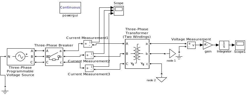
Fig. 1: Inrush Current Model without mitigation technique
Table 1 give maximum value of inrush current the result are obtained by simulating inrush current model without mitigation
.
Table1: Inrush current for without mitigation model
Fig 2: Inrush current without mitigation
C ontin uous
powe rg ui
-K-gain
v +
-Voltage Measurement
A
B
C a
b
c
Three-Phase Breaker A
B
C
a
b
c
Three-Phase Transformer (Two Windings)
N
A
B
C
Three-Phase Programmable Voltage Source
Scope1 Scope
node 2
node 1
1 s Integrator
i +
-C urrent Measurement3
i
+
-C urrent Measurement2
i +
-C urrent Measurement1
Inrush current in phases Peak value
Phase R 1256
Phase Y -525.00
1. Mitigation of Inrush current by using Pre-insertion Resistance technique
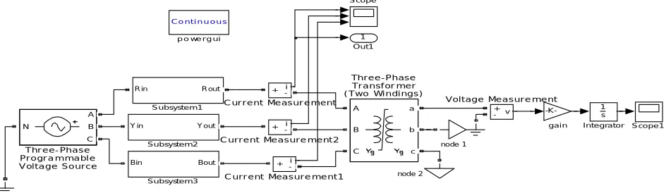
Fig 3: Model with Pre-insertion resistor method
The peak value of inrush current can be decrease by inserting the resistance between the generator and transformer. In this model initially circuit breaker 2 is closed. At the time of energisation of transformer winding the circuit breaker 1 is closed result in a resistance is inserted in series with the transformer which reduces the inrush current considerably. Table 2 shows tabulated value of inrush current for different value resistance from 0 to 400Ω. The graphical representation as shown in fig4 [23]
Table2: Inrush current for different value of resistance.
Value of resistor Ω Phase R Phase Y Phase B
0 1256.70 -525.00 -432.40
25 1133.60 -445.00 -414.00
50 1050.00 -423.40 -358.00
75 984.00 -406.42 -316.40
100 922.80 -389.30 -282.40
120 880.00 -375.60 -256.40
140 841.00 -367.64 -234.00
160 805.00 -355.00 -218.00
180 772.70 -345.00 -200.00
200 743.00 -336.22 -184.00
220 714.71 -327.06 -170.00
240 688.36 -317.40 -158.34
260 664.84 -309.04 -147.50
280 642.68 -302.00 -138.00
300 622.00 -295.00 -129.00
320 602.00 -288.20 -120.00
340 584.00 -281.50 -111.50
360 567.00 -275.20 -106.50
380 550.34 -269.00 -98.00
400 535.34 -264.00 -92.50
1 Out1 C o ntin u ou s
p o we rg ui
-K-gai n v + -Voltage Measurement A B C a b c Three-Phase Transformer (Two Windings) N A B C Three-Phase Programmable
Voltage Source Bin Bout
Subsystem 3 Y in Y out
Subsystem 2 R in R out
Subsystem 1 Scope1 Scope node 2 node 1 1 s Integrator i +
-C urrent Measurement2
i +
-C urrent Measurement1 i
+
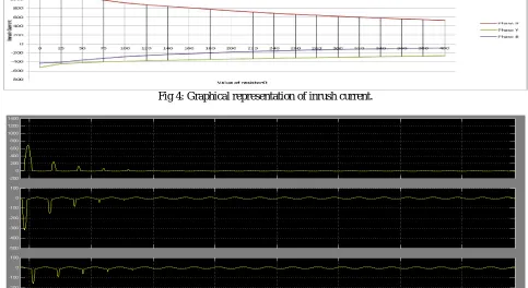
Fig 4: Graphical representation of inrush current.
Fig 5: Results of Pre-insertion Resistor Technique
The inrush current is reducing between the values of resistor 200 to 250 rapidly and mitigate at optimal value which is mention in table 3.
Table 3: Inrush current for R = 238Ω Optimal
Value of resistance Ω
Inrush current (Amp)
R-phase Y-phase B-phase
238 691.00 -319.80 -158.00
2. Mitigation of Inrush current by using Pre-insertion Resistance with Capacitor
Fig 6: Model with Pre-insertion Resistor with capacitor Technique.
C o n tin u o u s
p o we rg u i
-K-g a in
v +
-Voltage Measurement A
B
C a
b
c
Three-Phase Transformer (Two Windings) N
A B C Three-Phase Programmable
Voltage S ource Bin Bout Sub system 3
Y in Y out
Sub system 2
R in R out
Su bsyste m1
Scop e 1 Sco p e
node 2 node 1
1 s In te g rato r
i + -C urrent Measurement2
i +
-C urrent Measurement1
i +
The presence of residual flux in the transformer is mainly responsible for saturation of transformer core winding result in inrush current phenomenon. In order to reduce the effect capacitor is inserted in series with resistance. [5]
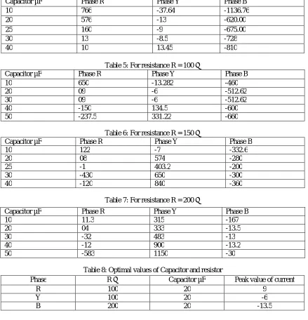
Table 4: For resistance R = 50 Ω
Table 5: For resistance R = 100 Ω
Capacitor µF Phase R Phase Y Phase B
10 650 -13.282 -460
20 09 -6 -512.62
30 09 -6 -512.62
40 -150 134.5 -600
50 -237.5 331.22 -660
Table 6: For resistance R = 150 Ω
Capacitor µF Phase R Phase Y Phase B
10 122 -7 -332.6
20 08 574 -280
25 -1 403.2 -200
30 -430 650 -300
40 -120 840 -360
Table 7: For resistance R = 200 Ω
Table 8: Optimal values of Capacitor and resistor
Capacitor µF Phase R Phase Y Phase B
10 766 -37.64 -1136.76
20 576 -13 -620.00
25 160 -9 -675.00
30 13 -8.5 -728
40 10 13.45 -810
Capacitor µF Phase R Phase Y Phase B
10 11.3 315 -167
20 04 333 -13.5
30 -32 483 -13
40 -12 900 -13.2
50 -583 1150 -30
Phase R Ω Capacitor µF Peak value of current
R 100 20 9
Y 100 20 -6
In the pre-insertion resistor with capacitor method get theoptimal values of capacitor and resistor which is mention in the table no. 8. At these values the mitigation of inrush current is shown in fig6.
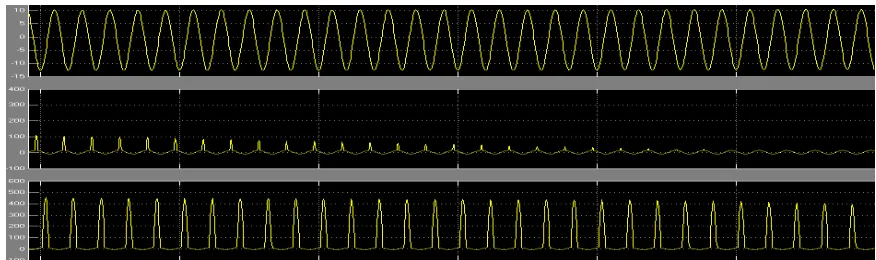
Fig 7: Current in phases R, Y and B with Pre-insertion resistor with capacitor technique
3. Mitigation of Inrush current by using Sequential Switching technique
Fig8: Model with Sequential Switching Technique
In sequential switching method each phase of transformer is energized at value of supply voltage of each phase. An instant value of supply voltage for each phase is different. The optimal value of switching for R-phase [0.02576, 0.0547] for Y-phase [0.024, 0.069] for B-phase [0.0309, 0.0957]. At these instant inrush current of each phase is not only reduces but also get mitigate. The results are given in fig.9. [17]
Fig 9: Current in phases R, Y and B of primary side with Sequential Switching method
IV.CONCLUSION
In this paper, effective methods are used to reduce the inrush current. In Pre-insertion resistance method by adding different value of resistance in series with transformer at primary side which mitigate inrush current. The best value of
1 Ou t1
C o ntinu o u s
p o we rg ui
-K-ga i n
v + -Voltage Measurement A
B
C a
b
c Three-Phase Transformer (Two Windings)
N A B C Three-Phase Programmable Voltage Source
Scop e 1 Sco pe
node 2 node 1
1 s In teg rato r
i + -C urrent Measurement3
i + -C urrent Measurement2
i + -C urrent Measurement1
resistance is 238Ω at this value the inrush current reduces about 50%.But to reduce the effect of saturation of transformer core inserting the capacitor with resistance which is known as a Pre-insertion resistance with capacitor method. The best value of capacitor is 20 µF at this value, inrush current reduces about 80%. The Sequential switching method is found to be easy to implement which has nullified inrush current approximately at their respective phases. Sequential switching method is a simple and easy method as compare to insertion resistance method and Pre-insertion resistance with capacitor method.
REFERENCES
[1] KunalWakod ,ShaikhSabir, NishantAdhau, Abuzar Khan, Prof. P. B. Shelke5Department of Electrical Engineering “A Case Study of Reduction of Single-Phase Transformer Magnetizing Inrush Current”International Journal of Research in Advent Technology (IJRAT) (E-ISSN: 2321-96.
[2] Balachandr D P College of Engineering Trivandrum, Sreerama Kumar R National Institute of Technology Calicut, Shimnamol V P College of Engineering Trivandrum, “A new technique for mitigation of transformer inrush current” C I R E D 19th International Conference on Electricity Distribution Vienna, 21-24 May 2007.
[3] Po-Tai Cheng, Wei-Ting Chen, Yu-Hsing ,ChenChih-Hsiang Wang CENTER FOR ADVANCED POWER TECHNOLOGIES “A Transformer Inrush Mitigation Method for Series Voltage Sag Compensators” 0-7803-9208-6/05/$20.00 © 2005 IEEE.
[4] AdalbertKonrad, Jean F. Brudny “An Improved Method for Virtual Air Gap Length Computation ” IEEE TRANSACTIONS ON MAGNETICS, VOL. 41, NO. 10, OCTOBER 2005.
[5] R.Rahnavard, M.Valizadeh, A. A.B.Sharifian, S.H.Hosseini “Analitical analysis of transformer inrush current and some new techniques for its reduction” IEEE.
[6] Mr.Pradeep J .Kotak,Prof.Alka Thakur “Comparative Analysis of Point on Wave Switching Technique & Pre-fluxing Technique to Mitigate In-rush Current in Three Phase Power Transformer” International Journal of Scientific & Engineering Research, Volume 5, Issue 11, November-2014 ISSN 2229-5518.
[7] SeyedAlirezaMousaviMirkalaei, Fahd Hashiesh “Controlled Switching to Mitigate Power Transformers Inrush Current Phenomenon” 978-1-4673-9682-0/15/$31.00 ©2015 IEEE.
[8] V. Oiring de Castro Cezar, L-L. Rouve, J-L. Coulomb, F-X. Zgainski, O. Chadebec, and B. Caillault “Elimination of inrush current using new Pre-fluxing method. Application to a single phase transformer.”978-1-4799-4389-0/14/$31.00 ©2014 IEEE.
[9] Mr. Pradeep J. Kotak M.Tech Student, SSSIST Sehore, M.P Prof. Alka Thakur Associate Professor, SSSIST Sehore, M.P“Inrush current reduction in three phase power transformer by using Pre-fluxing technique.”International journal of Electrical Engineering &Technology (IJEET) Volume 5, Issue 10, October (2014), pp. 23-32.
[10] Sachin R. Chavan PG Student, M. S. Potdar Assistant Professor Dept. of Electrical Engineering, PES College of Engineering Aurangabad (MS) – India “Magnetic Inrush Current of Transformer Reduce By Wave Switching Method with MATLAB Simulation Results.” International Journal of Engineering Trends and Applications (IJETA) – Volume 4 Issue 2, Mar-Apr 2017.
[11] Mr. Romit R. NandhaM.E. Scholar, Prof. Sachin V. RajaniAssistant Professor Electrical Engineering Department VVP Engineering college Rajkot. “Mitigate Inrush Current of transformer with Pre-fluxing Technique” May 2016 IJSDR Volume 1, Issue 5.
[12] NileshDeokar PG Student, Harpreet Singh H.O.D & Associate Professor, IET, Alwar, Rajasthan. “Mitigation And Analysis of Three Phase Transformer Magnetizing Inrush Current By Using Point on Wave Switching Method.” International Journal of Emerging Technology and AdvancedEngineering Website: www.ijetae.com (ISSN 2250-2459, ISO 9001:2008 Certified Journal, Volume 4, Issue 2, February 2014). [13] ApurvaKulkarni, RupeshJuware, VineshChoudhari, YogeshPawar “Mitigation of an Inrush Current of Power Transformer by using
PWM-Inverter based Series Voltage Compensator” IEEE.
[14] Raj Kumari , Prof. Sanjay Jain, Prof. Sanjay Gothwal Electrical Department RKDF university “Mitigation of Inrush Current of Transformer using Voltage Sag Compensator.” International Journal of Advance Research ,Ideas and Innovations In Technology Volume3 Issue1. [15] BarisKovan , Francisco de León Senior Member IEEE, DariuszCzarkowski, Member IEEE, ZivanZabar, Senior Member IEEE and Leo
Birenbaum Senior Member IEEE, “Mitigation of Inrush Currents in NetworkTransformers by Reducing the Residual Flux With an Ultra-Low-Frequency Power Source.” IEEE TRANSACTIONS ON POWER DELIVERY, VOL. 26, NO. 3, JULY 2011.
[16] Beerendra Singh, Mohamed Samir ,Ankit Bhatt “Mitigation of Transformer Magnetic Inrush Current” IJRD International Journal of Research & Development Organisation.
[17] KetanGohil, Jatinkumar Patel, Chirag Parekh “Reduction of Inrush Current for Transformer UsingSequential Switching Method”International Conference on Electrical, Electronics, and Optimization Techniques (ICEEOT) – 2016
[18] Vincent Molcrette, Jean-Luc Kotny, Jean-Paul Swan,AndJean-FranqoisBrudny, member IEEE Laboratoire des SystkmesElectrotechniques et Environnement. Universited’Artois - F SA. - TechnoparcFutura - 62400 - Bethune – FRANCE “Reduction of Inrush Current in Single Phase Transformer Using Virtual Air Gap Technique.” IEEE TRANSACTIONS ON MAGNETICS, VOL. 34, NO. 4, JULY 1998.
[19] F. Fard Ali Asghar [email protected] and K. P. [email protected] Faculty of Engineering, Multi Media University, “ Reduction of three phase transformer magnetizing inrush current by use of point on wave switching method.” STUDENT CONFERENCE ON RESEARCH AND DEVELOPMENT (SCOReD 2009 )16-18 Nov. 2009, UPM Serdang, Malaysia.
[21] Gopika R, DeepaSankarDepartment of Electrical & Electronics Engineering, AdiShankara Institute of Engineering Technology, Kalady, India “Study on Power Transformer Inrush Current” IOSR Journal of Electrical and Electronics Engineering (IOSR-JEEE) e-ISSN: 2278-1676,p-ISSN: 2320-3331, PP 59-63 www.iosrjournals.org
[22] Akash U. [email protected], K. Kamal [email protected] Zeal College of Engineering and Research Narhe, Pune, Maharashtra, India “To Reduce The Magnetic Inrush current By Point Wave Switching Method.” International Journal of Industrial Electronics and Electrical Engineering, ISSN: 2347-6982 Volume-4, Issue-9, Sep.-2016.
[23] S. JamaliArand, M. Saeedi, S. Masoudi “Transformer inrush current mitigation using controlled switching and magnetic flux shunts” International Journal of Energy and power Engineering.
[24] Shan Gao , Xinchun Lin, Shangjun Ye, He Lei, Yong Kang State Key Laboratory of Advanced Electromagnetic Engineering and Technology, School of Electrical & Electronic Engineering, Huazhong University of Science and Technology, Wuhan, Hubei Province, People’s Republic of China “Transformer inrush mitigation for dynamic voltage restorer using direct flux linkage control.” IET Power Electronics.
[25] D. P.Balachandran,College of Engineering, Trivandrum, Kerala, India, R.Sreerama Kumar,National Institute of Technology, Calicut Kerala, India & B.JayanandGovt. Enginering College, Thrissur, Kerala, India. “Volt-Second Balance Method for Mitigation of InrushCurrent in Single Phase Transformers.” International Journal of Power System Operation and Energy Management ISSN (PRINT): 2231 – 4407, Volume-1, Issue-4, 2012.