Type of the Paper (Article.)
1
Preparation ofCuONPs@PVDF/non-woven polyester
2
composite membrane: structural influence of
3
nanoparticles addition
4
Claudio A. Terrazaaϕ, Rudy Martina, Cesar Saldíasb, MarjorieGonzáleza, Ángel Leivabϕ**, Alain
5
Tundidor-Cambaaϕ*
6
aResearch Laboratory for Organic Polymers (RLOP), Faculty of Chemistry, Pontificia Universidad Católica de
7
Chile, P.O. Box 306, Post 22,Santiago, Chile.
8
bDepartment of Physical Chemistry, Faculty of Chemistry, Pontificia Universidad Católica de Chile, P.O. Box
9
306, Post 22,Santiago, Chile.
10
ϕEnergy Research Center. Pontificia Universidad Católica de Chile, Chile
11
*Correspondence: [email protected]; Tel: +56 223541199
12
** Correspondence: [email protected]; Tel: +56 223544392
13
14
Abstract: Membrane distillation techniques appear as one of the most promise alternative to
15
guarantee the availability of potable water in time of scarce of this essential resource. For
16
membrane preparation, polyvinylidene fluoride (PVDF) is preferred due to the easier synthesis
17
procedures with respect to other fluorine based polymers. In this work, copper oxide nanoparticles
18
(CuONPs) at different weight percent (wt.%), embedded in PVDF membranes supported on
19
non-woven polyester fabric (NWPET) were prepared by the phase-inversion method, and
20
characterized by spectroscopy (ATR-FTIR, Raman) and electron microscopy techniques (SEM). The
21
PVDF deposited onto the NWPET was highly composed by its polar -phase (F( )= 53 %) which
22
was determined from the ATR-FTIR spectrum. The F( ) value was kept constant, in the whole
23
range of CuONPs studied (2-10 wt.%) as was determined from the ATR-FTIR spectrum. The
24
absence of signals corresponding to CuONPs in the ATR-FTIR spectra and the appearance of peaks
25
at 297, 360 and 630 cm-1 in the Raman spectra of the membranes suggested that the CuONPs are
26
preferably located in the inner of the membrane but not on its surface. The membrane
27
morphologies were characterized by SEM. From the obtained SEM micrographs, a decrease and
28
increase in the amount of micropores and nanopores, respectively, near to the surface and
29
intercalated in the finger-like layer were observed. As result of the CuONPs addition, the
30
nanopores in the sponge-like layer decrease in size. The values of water contact angle (WCA)
31
measurements showed a trend to decrease from 94° to 80° upon the addition of CuONPs (2-10
32
wt.%) indicating a diminish in the hydrophobicity degree of the membranes. Apparently, the
33
increase in the amount of nanopores near to the surface decreased the membrane roughness
34
becoming less hydrophobic.
35
36
Keywords: Membrane distillation, polyvinylidene fluoride, copper oxide nanoparticles, membrane
37
morphology.
38
39
40
41
42
43
1. Introduction
44
It is expected that for 2025, the total water shortage will affect 1.8 billion people around the
45
world and the 66% of total populations could be living under water stress conditions. The need to
46
find adequate technologies to supply water and guarantee the livelihood of the human being is a
47
task to accomplish in the short-medium term. Oceans represent the ~97% of the global water reserves
48
and therefore water desalinization techniques have gained the attention to fulfill its demand in a
49
potable form [1]. Accordingly, Membrane Distillation (MD) technique appears as one of the most
50
promising technologies to obtain potable water from seawater [2].
51
Membrane distillation is a separation process from which vapor molecules of water, driven by
52
a thermal gradient, pass through a porous hydrophobic membrane [3]. This technique displays
53
several advantages compared to other existing ones (thermal desalinization and reverse osmosis),
54
such as a very high rejection of non-volatile solute, lower operating temperature and pressure and
55
the possibility to use low-grade energy sources (e.g., waste heat) as well as the use of renewable
56
energy sources (e.g., solar and geothermal). The reasons mentioned above not only make the MD an
57
economically feasible solution but also emerges as an environmentally friendly alternative for water
58
purification.
59
Considering the characteristics of the separation process, the membranes for MD should have
60
high permeability, low tendency to fouling, high chemical and thermal stability and a relatively high
61
hydrophobic degree. These features can be achieved by controlling the thickness, porosity, mean
62
pore size, pore size distribution, geometry and composition of the membranes. The hydrophobicity
63
is a crucial parameter and should be high enough to withstand a high liquid entry pressure (LEP).
64
This should allow that only the water vapor enters the pores of the membrane without
65
moistening[1,3].
66
The most common hydrophobic membranes used for MD are made up of fluoropolymers. From
67
this type of polymers i.e., polytetrafluoroethylene (PTFE) and polyvinylidene fluoride (PVDF) has
68
been widely applied due to their higher mechanical, chemical and heat resistance in comparison
69
with other hydrophobic materials [1]. Although PTFE is the most hydrophobic, it exhibits low
70
solubility in commons solvents, membranes fabricated from this polymer should be obtained by
71
stretching or thermal methods which lead to a relatively low porosity and restricts their
72
processability. Conversely, PVDF is soluble in varied common solvents which would allow the
73
incorporation of several additives, for the purpose of achieving new properties and preparation of
74
hierarchical composite membranes via non-solvent induced phase separation (NIPS) process or via
75
phase inversion techniques [4].
76
Important issues should be considered for the preparation of MD membranes with industrial
77
applications which are related to the mass flux, heat loss across the membrane, fouling problems and
78
mechanical strength. As inferred, these issues would play a key role in the efficiency of the process.
79
Flat-sheet PVDF membranes supported in non-woven polyester fabric (NWPET) yield
80
hydrophilic/hydrophobic layers wich additionaly to accomplish with the mass flux increases and
81
avoids the heat loss, confers significantly mechanical strength to the membrane. [1,3,5].
82
The modification of roughness and hydrophobicity of the membrane for increasing the
83
efficiency in separation has also been addressed in the past. A direct way to tune these parameters is
84
by incorporating inorganic nanoparticles into the membrane [4,6]. A widely used simple method to
85
incorporate such type of nanoparticles is by adding into a polymer solution [4,7,8]. Several inorganic
86
nanoparticles such TiO2, SiO2, Mg(OH)2, Al2O3, ZnO, CaCO3 have been incorporated into PVDF
87
membranes [4,9–12]. In this context, an type of metal nanoparticles that potentially would enable to
88
improve the performance and properties of MD is copper oxide nanoparticles (CuONPs). To the best
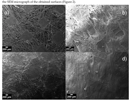
89
our knowledge, the use and properties of CuONPs in MD preparation (compared to other types of
90
metal oxide nanoparticles) has been scarcely reported in literature to date. [13–15].
91
CuONPs embedded into PVDF membranes trend to enlarge the surface pores and thickening
92
the finger-like layer [14,15]. This structural membrane features induced an increase in flux by ~150 %
93
at relatively low working-temperature (27.5 °C). Interestingly, the incorporation of CuONPs did not
94
membranes using copper oxide nanoparticles and graphene oxide as nanofillers[15]. The obtained
96
composite membrane showed a higher permeation since resulted in finger-like macro-voids and
97
thinner interconnected pores when compared to the non-filled membrane.
98
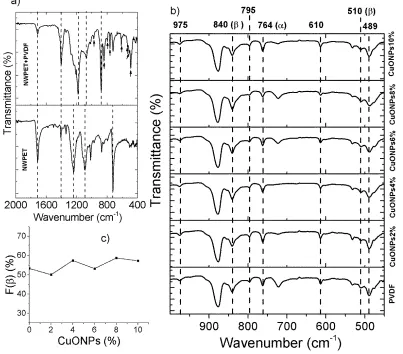
Although in the literature it is reported the preparation of CuONPs PVDF composite
99
membranes and PVDF membranes supported onto NWPET, none of the encountered reports deal
100
with the combination of both features. Accordingly and based on these previous reports it is
101
probable that the best performance of the here obtained membrane occurs in direct contact or
102
vacuum membrane distillation setups[14,16]
103
In the present work, we prepared and characterizeda novel CuONPs embedded PVDF
104
composite membrane, as the hydrophobic layer, supported onto non-woven polyester fabric as the
105
hydrophilic layer. Special emphasis is placed on the presence of the CuONPs which would influence
106
the size and morphology of the pores in each sublayer of the membrane. Additionally, acorrelation
107
between the values of water contact angles with the size of the pores distributed along the
108
membrane was detected. The motivation to carry out the study of the preparation and
109
characterization of these hydrophobic/hydrophilic composite membranes arises in order to offer
110
potential alternatives for technological solutions related to the water supply in the future.
111
2. Materials and Methods
113
Polydivinylfluoride (PVDF), copper (II) sulfate pentahydrate (CuSO4 x 5 H2O, 98.0 %) and
114
N,N-dimethtylformamide (DMF) were purchased from Sigma-Aldrich (Milwaukee, WI, USA) and
115
were used without further purification. Non-woven polyester fabric (NWPET) was purchased from
116
ImportadoraDilaco S.A. (Santiago, Chile).
117
Preparation of CuONPs
118
Copper oxide nanoparticles (CuONPs) were prepared using DMF as reducing and stabilizing
119
agent according to the previous reports in literature[17,18]. Typically, CuSO4 x 5 H2O (0.2 g) was
120
poured into a two-neck glass flask containing DMF (10 mL). The flask was connected to a reflux
121
system and heated to 120 °C for 5 h under constant stirring. The solution color turned from a light
122
green to yellowish as the copper oxide nanoparticles were formed. This solution served as stock for
123
the preparation of the doped CuONPs/PVDF membranes at different compositions.
124
Preparation of composite NWPET-PVDF membranes neat and doped with CuONPs
125
Selection of PVDF concentration for preparing the films
126
The composite NWPET-PVDF membranes were prepared by the phase inversion method as
127
follows: The casting solutions (1mL) at different PVDF concentrations (25 mg/mL, 50 mg/mL and 200
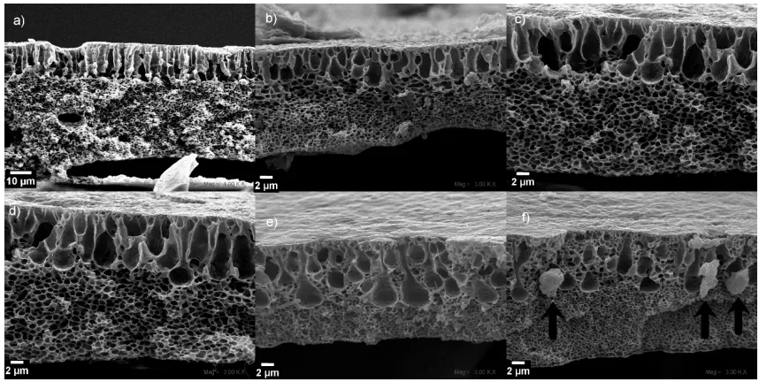
128
mg/mL) were stirred for 24 h at room temperature to guarantee a homogeneous polymer solution.
129
The resulting casting solutions were spread onto the NWPET fabric helped by a made-hand alumina
130
template (~1 mm of thickness), in order to minimize the polydispersity in films thickness (Figure 1).
131
The solutions spread on the NWPET surface was left stand for 20 s before they were sinking, for 24 h,
132
in distilled water at 25 °C to promote the precipitation of the PVDF. The prepared composite
133
membranes were left dried in a desiccator with P2O5 for further use.
134
Figure 1. Methodology used for preparing composite membranes.
135
Preparation of the NWPET-PVDF composite membranes doped with CuONPs
136
The CuONPs embedded in the membranes were prepared similar to as was mentioned above
137
but previously dissolving the PVDF (200 mg) in DMF solutions of CuONPs (1 mL) prepared from
138
the CuONPs stock solution (the volumes were adjusted to obtain 2, 4, 6, 8 and 10 wt.%
139
CuONPs/PVDF). The previously mixed solutions of PVDF and CuONPs were sonicated during 30
140
min to guarantee the dispersion of nanoparticles in the whole volume. Then, the solutions were
141
spread over the NWPET surface as was mentioned before.
142
Membrane morphology studies
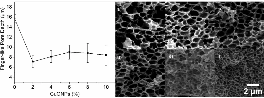
143
The membrane morphology was studied using a Scanning Electron Microscope Zeizz, model
144
EVO MA 10. The cross-section SEM micrographs were acquired by fracturing the membranes using
145
liquid nitrogen to freeze them and a surgical scalpel to cut the NWPET. The membranes were coated
146
with gold, using a Cressington-108 auto Sputter Coater. The measures and process of the obtained
147
SEM micrographs was performed using the free ImageJ (version 1.46J/Fiji) software from the
148
National Institute of Health. USA[19].
ATR-FT-IR and Raman spectroscopy
150
Infrared spectra were recorded on a Perkin-Elmer Spectrum-Two spectrometer with a UATR
151
unit coupled. The deposited polyester PVDF face was directly positioned over the diamond, pressed
152
until the 30% of the total supported pressure and scanned in the range of 4000 to 500 cm-1 with a
153
resolution of 1 cm-1. The -phase fraction (F()) of the different PVDF covered NWPET was
154
determined from the absorbance of the IR bands at 764 cm-1( )and 840 cm-1 using the equation
155
1[20].
156
( ) =
. + ( )
157
Raman Spectra were recorded on a DeltaNu benchtop Raman spectrophotometer with a 785 nm
158
laser. For each sample, ten spectra were recorded for each one with a 5s of integration time.
159
Contact angle measurements
160
The contact angle was determined by the technique of the sessile drop using a Dataphysics
161
OCA 20. A syringe, connected to a capillary of Teflon of approximately 2 mm of internal diameter
162
was used to deposit the water drop on the samples. All measurements were done at room
163
temperature. The acquisition of the images was carried out by computational processing of the drop
164
profile on the membranes.
165
3. Results and Discussion
167
3.1 Determination of PVDF concentration to prepare the composite membranes
168
The concentration of PVDF solution to ensure the total covering of the NWPET surface was
169
determined by spreading, onto the fabric, polymer solutions at 25, 50 and 200 mg/mL and recording
170
the SEM micrograph of the obtained surfaces (Figure 2).
171
172
Figure 2. SEM micrograph of a) neat NWPET fiber (a) and covered by depositing the casting solution
173
at b) 25 g/L, c) 50 g/L and d) 200 g/L of PVDF concentration. (Magnification 21x; scale bar 200 m).
174
The NWPET fabric is composed of PET fibers randomly aligned and jointed by the pressing of
175
the fabric (squares shapes in Figure 2a). As can be noted, by using the lowest PVDF concentration
176
(Figure 2b) a heterogeneous surface morphology was obtained. At this concentration, the polymer
177
amount is not enough to cover all the surface showing certain domains of the PVDF films
178
intercalated within the NWPET. When the PVDF concentration is incremented to 50 mg/mL, the
179
surface appears totally covered; however the pattern of the pressed fabric and also the fibers
180
contours are observed (Figure 2c). This would indicate that despite the film thickness a
181
homogeneous surface is not observed. At the highest PVDF concentration, the surface is apparently
182
covered (Figure 1d) although some fabric fibers ( it is likely that those fibers are far from the pressure
183
zones far from the pressing zones) still emerging at the surface of films as detected by ATR-FTIR
184
spectroscopy. Thereby, we considered that this concentration (200 mg/mL) was adequate to prepare
185
the flat-sheet surfaces as higher concentration the viscosity of the medium increased considerably..
186
3.2 ATR-FT-IR and Raman CuO@PVDF Characterization
187
The PDVF covered NWPET prepared in absence and presence of CuONPs were characterized
188
by ATR-FT-IR and Raman spectroscopy (Figure 3). Figure 3a shows the ATR-FT-IR spectra recorded
189
to the neat and covered NWPET with PVDFfilms. The FT_IR spectrum of neat NWPET shows the
190
characteristic peaks of this material at 1713 cm-1 (-CO stretching), 1238 cm-1 (-C(CO)O- stretching)
and 1092 cm-1 (-OCC- stretching). When PVDF solution was spread over NWPET surface, the peaks
192
at 1713 cm-1 and 1238 cm-1 decrease in intensity while the peak at 1092 is overlapped by a new intense
193
band at 1182 cm-1. This band corresponds to the asymmetric stretch of the -CF2 while the symmetric
194
component was recorded at 1073 cm-1.
195
196
Figure 3. ATR-FTIR spectra of a) neat NWPET and PVDF covered NWPET and b) NWPET-PVDF
197
membranes prepared at different CuONPs/PVDF compositions. c) Dependence of the -phase
198
fraction with the CuONPs/PVDF composition.
199
The infrared spectrum of PVDF mainly covers the low wavenumber region (Figure 3b). The
200
-CF2 wagging (489 cm-1) and bending (610 cm-1), the skeletal bending (764 cm-1), the -CH2 rocking
201
(795 cm-1) and twisting (975 cm-1) are some of the peaks characteristic of the non-polar -phase of
202
PVDF (indicated by black arrows, Figure 3a) [13,21,22]. Two peaks, labeled with black arrows in
203
Figure 3a (at 510 cm-1 and 840 cm-1corresponding to the -CF2 stretching -CH2 rocking, respectively)
204
were also recorded. These peaks would indicate the presence of a -phase of the PVDF (-PVDF).
205
The intensity of the peak at 840 cm-1 suggests an important contribution of the polar -PVDF to the
206
polymer structure. Interestingly, in neat PVDF prepared by phase inversion methods, the fraction of
207
the polar -phase in the polymer structure is very low (F()<35%) [13,22]. The F() value of the
208
polymer deposited onto the non-woven PET indicates that the 53 % corresponds to the -phase.
209
These results suggest that the adhesion of the PVDF to NWPET favors the -phase conformation.
210
Thereby, the observed changes in the intensities of the signals as well as the presence of others
211
additional corresponding to the PVDF, help confirm the presence of the polymer on the NWPET
212
surface.
213
The infrared spectrum of the PVDF films prepared in presence of CuONPs is shown in Figure
214
of the signals. (note the signals labeled by dashed lines). To verify the effect of the addition of
216
CuONPs in the crystallinity of the polymer, the fractions of F() were determined (Figure 3c) for
217
each sample.
218
It is reported that the addition of metal oxide nanoparticles to the PVDF casting solution causes
219
the - to -phase conversion [13,22]. As can be noted, the F() values are similar within the studied
220
CuONPs composition range (2-10 wt. %). This result could suggest that the crystallinity of the PVDF
221
films is mainly influenced by the deposition onto the non-woven PET and not by the addition of
222
CuONPs. Independently of the CuONPs not evidences of these were encountered in the ATR-FTIR
223
spectrum. The absence of a peak corresponding to Cu-O strength at 532 cm-1 indicates that CuONPs
224
are not present, at least, at the films surface.
225
In order to explore more deeply into the polymer films and detect the presence of CuONPs,
226
Raman spectra to the PVDF films prepared at different concentrations of CuONPs were recorded.
227
Raman spectra were recorded using a laser of 785 nm wavelength to guarantee its penetration into
228
the sample. The Raman spectrum of the NWPET-PVDF (Figure 4), in the lower wavenumber region
229
shows the characteristic signals of PVDF at 284, 410, 498 and 609 cm-1 [21]. The NWPET-PVDF films
230
prepared with CuONPs, show three additional peaks at 297, 360 and 630 cm-1 (arrows in Figure 4).
231
These peaks are assigned to the three Raman active modes of the CuO (Ag + 2Bg) evidencing the
232
presence of the CuONPs embedded into the polymer matrix [23].
233
234
Figure 4.Raman spectra of the NWPET-PVDF membranes prepared at different CuONPs/PVDF
235
wt.%.
236
A possible explanation of the absence of CuONPs on the NWPET-PVDF surface is due to their
237
relatively easy dispersability in water, the precipitation kinetics of the polymer and the diffusion rate
238
of the CuONPs through the polymer media. The rapid precipitation of the polymer, upon sinking
239
the PVDF impregnate NWPET in water, causes that the CuONPs near to the interface escapes from
240
the media giving raise to the retention of nanoparticles during the precipitation process. It is likely
242
that the CuONPs are present deeper in the pores of NWPET-PVDF membranes[14].
243
3.3 SEM characterization
244
To analyze the pore morphologies of the prepared membranes at different CuONPs
245
compositions, the corresponding cross-section SEM micrographs were recorded (Figure 5). The
246
membranes are composed from a top PVDF layer attached to a second one formed by the NWPET
247
fabric (Figure 1). The PVDF and NWPET layers exhibit pores with finger-like and sponge-like
248
morphologies, respectively. The size of PVDF and NWPET pores is in the order of micrometers and
249
nanometers, respectively. This pattern was observed in all the prepared membranes (Figure 5).
250
251
252
Figure 5. Cross-section SEM micrographs of the PVDF-NWPET samples a) neat PVDF-NWPET and
253
b-f) doped with 2, 4, 6, 8, 10% of CuONPs; respectively. The scale bars represent 2 m, unless a) (0 %)
254
that is 10 m.
255
The finger-like pores of the composite membranes in absence of CuONPs, appears aligned and
256
extended to the center of the membrane in a compact distribution. The sponge-like and finger-like
257
porous layers are well defined by a linear boundary along all the membrane as can be observed in
258
Figure 5a.
259
The addition of the CuONPs to the casting solution causes the loss of the mentioned above
260
linear boundary even at lower concentrations. Although, at 2 wt.% of CuONPs the linear finger-like
261
structures dominates the morphology (Figure5b). By increasing the CuONPs content to 4 wt.% and 6
262
wt.%, Figure 5c and 5d; respectively, the pores adopt a tear-like morphology. Interestingly, at higher
263
amounts of CuONPs (over 6 %), the sponge-like layer growth upward to the surface, surrounding
264
and therefore diminishing the number of tear-like pores (Figure 5e). At the highest amount of
265
CuONPs (10%), the membrane morphology is dominated by the sponge-like structure with certain
266
micropores, apparently from the collapsing of the tear-like pores. Additionally, at this concentration
267
some crystalline structures located at the boundary between the sponge and tear-like pores are
268
observed (Figure 5f, arrows). These structures should correspond to the CuONPs due to at high
269
concentration tends to aggregates to diminish the excess of surface energy related with their size. It
270
is possible to infer that under the used conditions, this aggregation occurred at concentration higher
271
than 8 wt.%, since in the other cross-sectioned SEM micrographs (wt.% < 8%) these structures were
272
not observed. Similar results have been reported in mixed composite PVDF membranes prepared in
273
presence of graphene oxide and CuxO (x=1 or 2) nanoparticles [14,15].
The presence of CuONPs not only affected the morphology of the finger-like layer but also the
275
depth of these have a markedly decrease at the lowest CuONPs content (2%) (Figure 6). The addition
276
of 2% of CuONPs causes an increase in the viscosity of the solution [14]. Consequently, the ability of
277
water to penetrate into the casting solution and form finger-like pores decrease. As can be noted,
278
with the 2% of CuONPs, this effect is clearly noted. The increasing in the CuONPs content not
279
dramatically affected the pore depth (Figure 6, left panel. Additionally, the increasing of the
280
CuONPs amount causes that both the pore size of the sponge-like structure and layer thickness
281
decrease (Figure 6, right panel).
282
283
Figure 6. Effect of the CuONPs wt.% in the depth of the finger-like pores (left panel). SEM
284
micrographs of the sponge-like layer at different CuONPs content; a) 0 wt.%, b) 2 wt.%, c) 4 wt.%, d)
285
6 wt.%, e) 8 wt.% and f) 10 wt.%). All images has the same size.
286
The distribution, morphology and size of the pores in the PVDF membranes are influenced by
287
the contribution of the thermodynamic and the kinetic factors during the precipitation of the
288
polymer (demixing process). Thermodynamically, the higher the instability of the casting solution,
289
the high the demixing rate during the phase separation process. Therefore, more finger-like
290
structures and less sponge-like structures are formed. From the kinetic perspective, the higher the
291
viscosity of the casting solution, the lower the solvent/non-solvent exchange rate which causes a
292
retard in the demixing process. This retard results in the formation of less finger-like structure and
293
more sponge-like structure [24]. Therefore, we can suggest that the addition of CuONPs did not
294
affects the stability of the polymer solution (thermodynamic) during the demixing process, but the
295
precipitation rate (kinetic) due to the increase of the solution viscosity. Therefore, the membranes
296
structures here obtained are dominated by kinetics and not by thermodynamics of the phase
297
separation process.
298
3.4 Contact angle measurements
299
A crucial factor in the efficiency of the MD processes is the membrane hydrophobicity. In a
300
membrane, this parameter depends on its roughness and surface energy [24] Therefore, the
301
hydrophobicity of the obtained NWPET-PVDF composite membranes was evaluated by WAC
302
304
Figure 7. Dependence of the water contact angle with the amount of CuONPs (wt.%).
305
In absence of CuONPs, the NWPET-PVDF membrane shows a WCA higher than 90°, a
306
characteristic value for hydrophobic materials. By preparing the membrane with 2 wt.% of CuONPs,
307
the WCA decreases by c.a. 15 degrees, indicating a less hydrophobic character. Further increase in
308
the CuONPs content, i.e from 4 wt.% to 10 wt.% lead to a slow decrease in the WCA.
309
As was mentioned before, by ATR-FTIR, CuONPs were not detected at the membrane surface.
310
Additionally, the F() values did not varied with the CuONPs wt.%. From these two results, we can
311
suggest that the decrease in the hydrophobicity should not be related to a decrease in the surface
312
energy but to changes in the roughness of the membranes upon the addition of nanoparticles.
313
Figure 8 shows the surface and top skin cross-section SEM micrograph taken to the
314
NWPET-PVDF membranes prepared in absence (0 %) and presence of the CuONPs (2 to 10 wt.%).
315
The neat NWPET-PVDF membrane (Figure 8a) shows a porous and rough surface with pores sizes
316
larger than 200 nm. The addition of 2 wt.% of CuONPs to the casting solution causes that both, the
317
surface roughness and the pore sizes on itdecrease (< 200 nm) (Figure 8b). The trend to decrease of
318
both parameters continue by increasing the CuONPs wt.% from 4% to 10% (Figure 8c-f). At 10 wt.%
319
of CuONPs, an smooth and quasi absent of pores surface was obtained.
320
321
Figure 8. Top and cross-section SEM micrographs of the NWPET-PVDF membranes prepared a) in
322
absence (wt. 0%) and b-f) presence of CuONPs (2, 4, 6, 8 and 10 wt.%; respectively). Scale bars of
323
top-view= 200 nm, cross-section= 1 m.
324
By a simple inspection of the rectangles inset on top of each figure, it is possible to note that the
325
increases of the CuONPs wt.%, lead to a decrease of the micropores extended to the surface and an
326
distribution should be the responsible of the decrease of the surface roughness and hence the
328
observed decrease in the WCA measurements upon the addition of CuONPs.
329
4. Conclusions
330
PVDF membranes with different wt.% of CuONPs embedded and supported in NWPET can be
331
prepared by the phase inversion method. The deposition of PVDF solution on NWPET leads to an
332
enhancement of the polar -phase of the deposited polymer, which no varies with the amount of
333
CuONPs. In these composites membranes the CuONPs are located in the inner of the membrane.
334
The resulting membranes become less hydrophobic upon the addition of the nanoparticles. We
335
suggest that the loss in its hydrophobicity arises from the decrease of the membrane roughness and
336
not due to changes in its surface energy.
337
Acknowledgements:
338
The authors acknowledge to the project Corfo 13CEI2-21803 for the financial support.
339
340
References
341
1. Drioli, E.; Ali, A.; Macedonio, F. Membrane distillation: Recent developments and perspectives.
342
Desalination2015, 356, 56–84, doi:10.1016/j.desal.2014.10.028.
343
2. Alkhudhiri, A.; Darwish, N.; Hilal, N. Membrane distillation: A comprehensive review.
344
Desalination2012, 287, 2–18, doi:10.1016/j.desal.2011.08.027.
345
3. Hou, D.; Dai, G.; Wang, J.; Fan, H.; Zhang, L.; Luan, Z. Preparation and characterization of
346
PVDF/nonwoven fabric flat-sheet composite membranes for desalination through direct contact
347
membrane distillation. Sep. Purif. Technol.2012, 101, 1–10, doi:10.1016/j.seppur.2012.08.031.
348
4. Kang, G. dong; Cao, Y. ming Application and modification of poly(vinylidene fluoride) (PVDF)
349
membranes - A review. J. Memb. Sci.2014, 463, 145–165, doi:10.1016/j.memsci.2014.03.055.
350
5. Khayet, M.; Mengual, J. I.; Matsuura, T. Porous hydrophobic/hydrophilic composite membranes:
351
Application in desalination using direct contact membrane distillation. J. Memb. Sci.2005, 252, 101–113,
352
doi:10.1016/j.memsci.2004.11.022.
353
6. Warsinger, D. M.; Swaminathan, J.; Guillen-Burrieza, E.; Arafat, H. A.; Lienhard V, J. H. Scaling and
354
fouling in membrane distillation for desalination applications: A review. Desalination2015, 356, 294–313,
355
doi:10.1016/j.desal.2014.06.031.
356
7. Tijing, L. D.; Woo, Y. C.; Choi, J.-S.; Lee, S.; Kim, S.-H.; Shon, H. K. Fouling and its control in membrane
357
distillation—A review. J. Memb. Sci.2015, 475, 215–244, doi:10.1016/j.memsci.2014.09.042.
358
8. Qin, A.; Li, X.; Zhao, X.; Liu, D.; He, C. Engineering a highly hydrophilic PVDF membrane via binding
359
TiO<inf>2</inf> nanoparticles and a PVA layer onto a membrane surface. ACS Appl. Mater.
360
Interfaces2015, 7, 8427–8436, doi:10.1021/acsami.5b00978.
361
9. Wan, H.; Briot, N. J.; Saad, A.; Ormsbee, L.; Bhattacharyya, D. Pore functionalized PVDF membranes
362
with in-situ synthesized metal nanoparticles: Material characterization, and toxic organic degradation.
363
J. Memb. Sci.2017, 530, 147–157, doi:10.1016/j.memsci.2017.02.021.
364
10. Gao, J.; Huang, X.; Xue, H.; Tang, L.; Li, R. K. Y. Facile preparation of hybrid microspheres for
365
super-hydrophobic coating and oil-water separation. Chem. Eng. J.2017, 326, 443–453,
366
doi:10.1016/j.cej.2017.05.175.
367
11. Dong, C.; He, G.; Li, H.; Zhao, R.; Han, Y.; Deng, Y. Antifouling enhancement of poly(vinylidene
368
fluoride) microfiltration membrane by adding Mg(OH)2nanoparticles. J. Memb. Sci.2012, 387–388, 40–
369
12. Ng, L. Y.; Mohammad, A. W.; Leo, C. P.; Hilal, N. Polymeric membranes incorporated with metal/metal
371
oxide nanoparticles: A comprehensive review. Desalination2013, 308, 15–33,
372
doi:10.1016/j.desal.2010.11.033.
373
13. Dutta, B.; Kar, E.; Bose, N.; Mukherjee, S. Significant enhancement of the electroactive β-phase of PVDF
374
by incorporating hydrothermally synthesized copper oxide nanoparticles. RSC Adv.2015, 5, 105422–
375
105434, doi:10.1039/C5RA21903E.
376
14. Baghbanzadeh, M.; Rana, D.; Matsuura, T.; Lan, C. Q. Effects of hydrophilic CuO nanoparticles on
377
properties and performance of PVDF VMD membranes. Desalination2015, 369, 75–84,
378
doi:10.1016/j.desal.2015.04.032.
379
15. Zhao, C.; Lv, J.; Xu, X.; Zhang, G.; Yang, Y.; Yang, F. Highly antifouling and antibacterial performance
380
of poly (vinylidene fluoride) ultrafiltration membranes blending with copper oxide and graphene oxide
381
nanofillers for effective wastewater treatment. J. Colloid Interface Sci.2017, 505, 341–351,
382
doi:10.1016/j.jcis.2017.05.074.
383
16. Qtaishat, M.; Rana, D.; Khayet, M.; Matsuura, T. Preparation and characterization of novel
384
hydrophobic/hydrophilic polyetherimide composite membranes for desalination by direct contact
385
membrane distillation. J. Memb. Sci.2009, 327, 264–273, doi:10.1016/j.memsci.2008.11.040.
386
17. Pastoriza-Santos, I.; Liz-Marzán, L. M. Formation and Stabilization of Silver Nanoparticles through
387
Reduction by N,N-Dimethylformamide. Langmuir1999, 15, 948–951, doi:10.1021/la980984u.
388
18. Pastoriza-Santos, I.; Liz-Marzán, L. M. Formation of PVP-Protected Metal Nanoparticles in DMF.
389
Langmuir2002, 18, 2888–2894, doi:10.1021/la015578g.
390
19. Schneider, C. A.; Rasband, W. S.; Eliceiri, K. W. NIH Image to ImageJ: 25 years of image analysis. Nat.
391
Methods2012, 9, 671.
392
20. Sencadas, V.; Gregorio, R.; Lanceros-Méndez, S. α to β phase transformation and microestructural
393
changes of PVDF films induced by uniaxial stretch. J. Macromol. Sci. Part B Phys.2009, 48, 514–525,
394
doi:10.1080/00222340902837527.
395
21. Simoes, R. D.; Job, A. E.; Chinaglia, D. L.; Zucolotto, V.; Camargo-Filho, J. C.; Alves, N.; Giacometti, J.
396
A.; Oliveira, O. N.; Constantino, C. J. L. Structural characterization of blends containing both PVDF and
397
natural rubber latex. J. Raman Spectrosc.2005, 36, 1118–1124, doi:10.1002/jrs.1416.
398
22. Kar, E.; Bose, N.; Das, S.; Mukherjee, N.; Mukherjee, S. Enhancement of electroactive β phase
399
crystallization and dielectric constant of PVDF by incorporating GeO 2 and SiO 2 nanoparticles. Phys.
400
Chem. Chem. Phys.2015, 17, 22784–22798, doi:10.1039/C5CP03975D.
401
23. Xu, J. F.; Ji, W.; Shen, Z. X.; Li, W. S.; Tang, S. H.; Ye, X. R.; Jia, D. Z.; Xin, X. Q. Raman spectra of CuO
402
nanocrystals. J. Raman Spectrosc.1999, 30, 413–415,
403
doi:10.1002/(SICI)1097-4555(199905)30:5<413::AID-JRS387>3.0.CO;2-N.
404
24. Chen, Z.; Rana, D.; Matsuura, T.; Yang, Y.; Lan, C. Q. Study on the structure and vacuum membrane
405
distillation performance of PVDF composite membranes: I. Influence of blending. Sep. Purif.
406
Technol.2014, 133, 303–312, doi:10.1016/j.seppur.2014.07.015.