Article
1
Ceramic-Based 4D-Components: Additive
2
Manufacturing (AM) of Ceramic-Based Functionally
3
Graded Materials (FGM) by Thermoplastic
4
3D-Printing (T3DP)
5
Uwe Scheithauer 1,*, Steven Weingarten 1,Robert Johne 2, Eric Schwarzer 1, Johannes Abel 1,
6
Hans-Jürgen Richter 1, Tassilo Moritz 1 and Alexander Michaelis 1
7
1 Fraunhofer Institute for Ceramic Technologies and Systems, Dresden, Germany; www.ikts.fraunhofer.de
8
2 Fraunhofer Singapore, Singapore; www.fraunhofer.sg
9
* Correspondence: [email protected]; Tel.: +49-351-2553-7671
10
Abstract: In our study we investigated the additive manufacturing (AM) of ceramic-based
11
Functionally Graded Materials (FGM) by the direct AM technology Thermoplastic 3D-Printing
12
(T3DP). Zirconia components with a varying microstructure were additively manufactured by
13
using thermoplastic suspensions with different contents of pore forming agents (PFA) and were
co-14
sintered defect-free.
15
Different materials were investigated concerning their suitability as PFA for the T3DP process.
16
Different zirconia-based suspensions were prepared and used for AM of single- and multi-material
17
test components. All samples were sintered defect-free and in the end we could realize a brick
wall-18
like component consisting of dense (<1% porosity) and porous (approx. 5% porosity) zirconia areas
19
to combine different properties in one component.
20
The T3DP opens the door to AM of further ceramic-based 4D-components like color or
multi-21
material, especially multi-functional components.
22
Keywords: additive manufacturing (AM); Functionally Graded Materials (FGM); Thermoplastic
23
3D-Printing (T3DP; ceramics; ceramic-based 4D-components; zirconia; graded microstructure
24
25
1. Introduction
26
The term “4D Printing” was initially used by Tibbits and Sheil [1] and describes a technology,
27
which was developed as a collaboration between the Self-Assembly Lab, Stratasys and Autodesk to
28
manufacture customizable smart materials. By using an additive manufacturing (AM) device,
29
polymer multi-material components with the added capability of shape-transformation from one
30
state to another can be realized. This offers the possibility to include functionalities like actuation,
31
sensing and material logic directly into the components [2]. Additively manufactured multi-material
32
components can transform from any 1D strand or 2D surface into 3D shape or morph from one 3D
33
shape into another. Using only water, heat, light or other simple energy input, this technique offers
34
adaptability and dynamic response for structures and systems of all sizes [2].
35
In particular, for ceramic components it is very challenging to realize such properties. The reason
36
for this challenge is, the thermal treatment after the AM process being necessary to generate the
37
ceramic properties. In order to obtain a multi-material composite it is fundamental to successfully
co-38
sinter the paired powders in the composite material. Since the sintering of the components is
39
performed at the same temperature and atmosphere, it is a prerequisite for all materials to have a
40
comparable sintering temperature and behavior (starting temperature of sintering, shrinkage
41
behavior). To avoid critical mechanical stress during cooling, it is also important that the coefficient
42
of thermal expansion of all materials is approximately equal.
43
Nevertheless it is possible to realize ceramic components with variety of properties by realizing
44
a graded microstructure or material gradients. These composites are called functionally graded
45
material (FGM) [3]. To achieve unprecedented properties of ceramic components we combine the
46
benefits of AM with the benefits of FGM to “4D materials”.
47
In a FGM the properties change gradually with position [3], which generates new fields of
48
application. Graded microstructures as a combination of two or more materials, for example in
49
ceramic-metal composites, result in innovative, multi-functional property combinations, such as hard
50
and ductile, electrically or thermally conductive and insulating, magnetic and nonmagnetic.
51
Conceivable applications are in a variety of industrial and medical fields, for example as cutting tools,
52
wear resistant components, energy and fuel cell components or as bipolar surgical tools [4-9]. Figure
53
1 shows metal-ceramic components for different applications manufactured by
two-components-54
ceramic injection molding (2C-CIM). Furthermore the manufacturing of two-color components is
55
possible with 2C-CIM (Figure 2).
56
57
Figure 1. metal-ceramic composites manu-factured by 2C-CIM
Figure 2. two-colored zirconia components manufactured by 2C-CIM
58
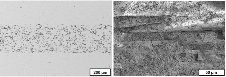
Components with different porosities combine different properties in the gradient structure
59
regarding thermal conductivity and capacity, density, mechanical strength, and elastic modulus
60
which shall result e.g. in improved thermal shock properties [10]. Figure 3 shows the SEM-image of
61
a cross-section of a sintered MgO-ZrO2-component with graded porosity and Figure 4 shows the
62
crack surface after a crack deflection during a bending test occurred, due to the graded microstructure
63
and varied Young’s modulus [11].
Figure 3. cross-section of sintered MgO-ZrO2 component with graded microstructure
Figure 4. crack surface of CaAl-Al2O3 component after bending test
66
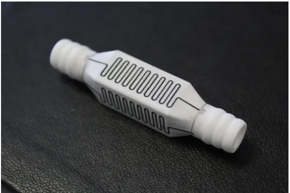
AM technologies offer the possibility of a tool-free production of components with extremely
67
complex geometry which cannot be attained by any other shaping technique (Figure 5 and Figure 6).
68
According to ASTM additive manufacturing is a “process of joining material to make objects from
69
3D model data, usually layer upon layer” [12]. In the plastics industry AM methods are already
70
commercialized to a large extend and the equipment for 3D printing can be even bought for home
71
applications. In the field of metals, more and more materials can be processed as well. For processing
72
ceramic materials, the technical application of AM technologies has been limited so far. However,
73
ceramics have been studied in AM processes ab initio with the development of the different AM
74
technologies since about 25 years [13, 14]. All established AM technologies have also been tested for
75
ceramic materials [15-41]. AM technologies can be classified according to the state of the material that
76
is used – powder materials, liquid materials and solid materials [42, 43] or according to the kind of
77
material deposition and solidification [44]. Lithography-based Ceramic Manufacturing (LCM) allows
78
the AM of dense alumina and zirconia components with extraordinary complex geometries [20-22,
79
45, 46].
80
81
Figure 5. alumina heat exchangers, additively manufactured by Lithography-based Ceramic Manufacturing (LCM)
Figure 6. alumina static mixer, additively manufac-tured by LCM
82
Several technologies are known for the production of FGM. Very good overviews are given by
83
Kieback et al. [3], Naebe et al. [47] as well as Moritz et al. [48]. Conventional shaping technologies can
84
be used to produce FGM like powder pressing [49], slip casting [50, 51], powder injection molding
85
[52, 53], tape casting [11, 54-56] or a combination of conventional shaping technologies like
inmold-86
labeling as a combination of tape casting and injection molding [57, 58].
87
First studies on AM of FGM-components were published about 20 years ago [59-61]. The
88
Multiphase Jet Solidification (MJS)-technology based on thermoplastic binder systems filled with
89
high contents of ceramic particles is nearly similar to the Fused Filament Fabrication (FFF) / Fused
90
Deposition Modeling (FDM®) technology. A hot powder-binder mixture (feedstock) with suitable
91
flow properties was deposited with an extrusion jet moved in two dimensions. During cooling the
92
mixture solidified and a free-standing body was formed. By using a two piston construction
combined with a small static mixing chamber, the powder composition was varied from layer to layer
94
and three dimensional graded SiC-TiC components could be formed [59, 60].
95
Zhang et al. used Laminated Object Manufacturing (LOM) to manufacture TiC-Ni-FGMs. Green
96
tapes with different compositions were produced, cut by a laser, stacked and laminated [61].
97
Another approach is the functionalization of additively manufactured and sintered ceramic
98
components subsequent to its generation. Figure 7 shows an alumina component manufactured by
99
Lithography-based Ceramic Manufacturing (LCM), sintered at 1600 °C and subsequently
100
functionalized with electrically conductive heater structures by Aerosol-printing [48].
101
102
Figure 7. post-functionalized additively manufactured alumina component
103
Direct AM technologies are more suitable for AM of multi-material components than indirect
104
AM technologies because of the selective deposition of the used material. The latter ones are based
105
on the selective solidification of material which was deposited all-over the entire layer. Therefore the
106
areas which have not been solidified are occupied by non-solidified material which have to be
107
removed before a second material can be deposited in these areas. Using direct AM technologies a
108
second material and further ones can be deposited directly beside the already deposited and
109
solidified first material.
110
In our study we investigated the AM of ceramic-based FGM by the direct AM technology
111
Thermoplastic 3D-Printing (T3DP). Zirconia components with a varying microstructure were
112
additively manufactured by using thermoplastic suspensions with different contents of pore forming
113
agents (PFA) and were co-sintered defect-free.
114
2. Experimental
115
2.1. Thermoplastic 3D-Printing
116
117
T3DP bases on the selective deposition of particle-filled thermoplastic suspensions not over the
118
entire surface, but instead only at the required spots [62]. Different suspensions can be deposited
119
beside each other in each single layer and bulk material as well as property gradients can be realized
120
within the additively manufactured green components [63-65].
121
Several heatable dispensing units which are moved over a fixed platform in all three spatial
122
directions deposit the suspensions. The thermoplastic suspensions are heated until they are in a
123
flowable state. They are deposited at the desired position, and solidify immediately on cooling as
124
well as lacking shear forces. The solidification takes place almost independently of the physical
125
properties of the used powders so even hard metal components can be manufactured [66]. Several
supply containers and dispensing units can be used for the localized deposition of different materials,
127
including supporting structures, in one and the same component.
128
2.2. Used materials
129
As ceramic material the yttria-stabilized zirconia powders TZ-3Y-E by Tosoh Corporation of
130
Japan was used.
131
Three different materials were investigated concerning their behavior as a PFA. ARBOCEL
132
UFC100 of the company J. Rettenmaier Söhne GmbH + Co KG is a cellulose powder based on cellulose
133
fibers with an average particle size of 6 μm – 12 μm. The decomposition temperature of this material
134
is about 200 °C and corresponds to the decomposition temperature of a second polysaccharide (PS)
135
powder (starch) with rounder shape and a maximum diameter below 25 μm. CERETAN MA 7008
136
(Münzing Chemie GmbH) is an amide of a carboxylic acid with a decomposition temperature of
137
about 150 °C and a d99 of 8 μm. It was selected to investigate the suitability as PFA in spite of the
138
significant lower decomposition temperature.
139
2.3. Feedstock preparation
140
The different zirconia suspensions were prepared by dispersing the powder together with the
141
PFA in a thermoplastic binder system basing on a mixture of molten paraffin and beeswax. The
142
dispersion and homogenization took place in a heatable dissolver (Dissolver DISPERMAT CA 20-C,
143
VMA-Getzmann GmbH) by stirring for 4 h. Suspensions with 36 vol.-% and 40 vol.-% were prepared.
144
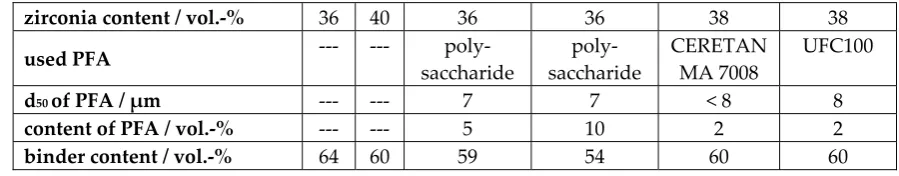
The content of PFA was varied for each material. Table 1 summarizes the composition of the
145
different thermoplastic suspensions.
146
147
Table 1. composition of used thermoplastic suspensions
zirconia content / vol.-% 36 40 36 36 38 38
used PFA --- ---
poly-saccharide poly-saccharide CERETAN MA 7008 UFC100
d50 of PFA / µm --- --- 7 7 < 8 8
content of PFA / vol.-% --- --- 5 10 2 2
binder content / vol.-% 64 60 59 54 60 60
2.4. Preparation of single- and multi-material test components
148
The test samples were additively manufactured by using micro dispensing systems of Vermes,
149
Germany. Four of them are mounted on our xyz-laboratory rig, which can operate alternately. One
150
dispensing system was used to manufacture the single-material components, two of them were used
151
for the manufacturing of multi-material test components.
152
The dispensing parameters had to be adjusted for each suspension due to the different
153
rheological behavior. The deposition of the droplets happened with a frequency up to 100 Hz and the
154
axes were moved with a maximal velocity of 50 mm/s.
155
The green samples were debinded in a powder bed at a very low heating rate, in a first step
156
under air-atmosphere up to 270°C (heating rate 4 K/h) and then after removing the powder in a
157
second step under air-atmosphere up to 900°C (12 K/h). Afterwards the components were sintered
158
under air-atmosphere at 1350 °C (3 K/min) for 2 hours.
159
2.5. Characterization methods
160
The particle size distribution of the utilized powders and PFA were measured by a laser
161
diffraction method (Mastersizer 2000, Malvern Instruments Ltd., United Kingdom). Electron
162
scanning microscopy images have been used to characterize the shape of the particles.
163
To characterize the rheological behavior of the zirconia suspensions, a rheometer (Modular
164
Compact Rheometer MCR 302; Anton Paar, Graz, Austria) adjustable between -25 to 200°C with a
plate/plate measuring system was used. The flow behavior was analyzed with an increasing shear
166
rate (0–10000 s-1) and at varying temperatures between 85°C and 100°C. The torque was measured
167
and the viscosity calculated.
168
FESEM images of the sintered samples have been utilized to evaluate the samples density and
169
porosity. The FESEM images were converted into binary images by means of an open source software
170
called Image J, i.e. all pores were converted into black pixels and the ceramic particles into white
171
pixels. In order to calculate the samples porosity the software compares the number of the black and
172
white pixels of a converted image of a samples cross sections.
173
Additionally, the density was measured by Archimedes’ principle.
174
3. Results and discussions
175
3.1. FESEM-studies of used materials
176
The measured average particle size (d50) of the zirconia powder was with 0.37 μm by about one
177
order of magnitude larger than the average particle size stated by Tosoh (d50 = 0.04 μm).
FESEM-178
images showed that the untreated powder consists of very big granulates (diameter up to 100 μm)
179
which were crushed during the ultrasonic-treatment before the laser diffraction (Figure 8). Still, the
180
applied treatment was just insufficient regarding the deagglomeration of all the particles. But during
181
the feedstock preparation very high shear forces were realized which should deagglomerate all
182
particles.
183
Figure 8. FESEM-images of untreated zirconia powder
Figure 9 and Figure 10 show FESEM-images of two materials used as a PFA. ARBOCEL UFC100
184
bases on cellulose fibers and the particles have a fiber-fragments-like shape (Figure 9). The particles
185
of the PS powder have a polyhedral-like shape (Figure 10). The particle size investigated on
FESEM-186
images varied between 5 μm and 20 μm.
Figure 9. FESEM-images of ARBOCEL UFC100
189
Figure 10. FESEM-images of polysaccharide powder
190
The FESEM-images of the used PFA materials gives an explanation for the content of PFA which
191
could be realized in the different suspensions. With the starch powder (polysaccharide) a significant
192
higher content of PFA (up to 10 vol.-%) could be realized. For the other two materials the viscosity
193
increased significant for contents of more than 2 vol.-%. Probably this results from the higher and
194
rough surface of CERETAN MA 7008 and UFC 100 compared to the smooth surface of the starch
195
powder.
196
3.2. Rheological behavior of the thermoplastic suspensions
197
The results of the rheological measurements of the two zirconia suspensions without any content
198
of a PFA are summarized in Figure 11. The dynamic viscosity is displayed as function of the shear
199
rate in a double logarithmic plot with a shear rate range between 0.1 and 10000 s-1. All suspensions
200
show a shear thinning behavior at both temperatures. With increasing solid content and decreasing
201
temperature the dynamic viscosity increases.
Figure 11. rheological behavior of zirconia suspensions without any PFA
204
Figure 12. rheological behavior of zirconia suspensions with and without PFA at 100 °C
205
Figure 12 shows the dynamic viscosities as function of the shear rate at a temperature of 100 °C
206
for the different suspensions with and without PFA. The suspension without any PFA has the lowest
viscosity and by adding PFA the viscosity increases. However, all suspensions show a shear thinning
208
behavior with a dynamic viscosity of 1 Pa*s or lower at a shear rate of 5000 s-1 and therefore can be
209
utilized for T3DP. Table 2 summarizes the measured viscosities of the suspensions at different shear
210
rates and temperatures.
211
212
Table 2. dynamic viscosity of the suspensions at different shear rates
zirconia content / vol.-%
PFA: kind and content / vol.-%
tempe-rature
/ °C
shear rate / s-1
0,1 1 10 102 103 104
36 --- 85 3400 312 43,80 6,86 1,43 0,52
100 3420 309 38,30 6,03 1,07 0,32
40 --- 85 4600 414 56,60 8,98 2,16 0,59
100 3630 386 56,00 8,96 1,75 0,57
36 polysaccharide 5
85 3770 355 56,60 8,26 1,80 0,59
100 2510 240 42,40 8,48 1,45 0,45
36 polysaccharide 10
85 1800 374 79,30 10,30 2,47 0,65
100 5420 513 79,60 11,80 2,12 0,53
38 MA7008
2
85 2220 265 38,50 6,56 1,83 0,62
100 1130 140 32,50 5,11 1,18 0,43
38 UFC100
2
85 1770 214 31,60 5,34 1,63 0,60
100 1210 143 31,40 4,83 1,15 0,48
213
3.3. single-material components
214
After a screening of the deposition parameters it was realizable to manufacture test components
215
for each suspension. Figure 13 shows three views of a complex structure additively manufactured by
216
T3DP with the zirconia suspension without a PFA. The shown test components were realized without
217
a prerequisite utilization of any support structure respectively support material. After sintering, the
218
wall thickness of this structure was less than 0.8 mm. The manufacturing time for the green
219
component was approximately 30 minutes.
220
221
Figure 13. sintered zirconia test component additively manufactured by T3DP with 36 vol.-% zirconia particles in the suspension and without PFA; three different views
222
The FESEM-images of the cross-section of sintered zirconia test components additively
223
manufactured by T3DP with 36 vol.-% zirconia particles and without any PFA in the suspension are
shown in Figure 14. A very homogeneous microstructure almost without any porosity can be seen.
225
By utilizing ImageJ and five different FESEM-images an average porosity of 0.11 +/- 0.04% was
226
calculated. With Archimedes’ principle an average outer density of 5.90 +/- 0.04 g/cm³ and an average
227
inner density of 5.93 +/- 0.05 g/cm³ was investigated for 14 test samples.
228
229
Figure 14. FESEM-images of sintered zirconia test components additively manufactured by T3DP with 36 vol.-% zirconia particles and without PFA in the suspension
230
In addition test samples of the suspensions with PFA were manufactured. Figure 15 shows two
231
views of a green sample including 5 vol.-% PS as PFA, for instance.
232
233
Figure 15. green zirconia test components with 5 vol.-% PS as a PFA
234
The FESEM-images of the sintered test components additively manufactured by T3DP with the
235
suspensions which included 5 vol.-% PS (left) and 10 vol.-% PS (right) as PFA are summarized in
236
Figure 16. The images show a homogeneous distribution of the single pores with a nearly round
237
shape resulting from the polyhedron-like shape of the PS-powder as PFA. The average porosities
238
calculated with ImageJ on five images each are 5.02 +/- 0.43 % and 10.72 +/- 0.87 %, respectively. These
239
correspond almost exactly to the content of added PFA in the suspensions (5 vol.-% and 10 vol.-%).
Figure 16. FESEM-images of cross-sections of sintered zirconia test samples with 5 % PS and 10 vol.-% PS as PFA in the suspension
242
However, not every of the used materials operated as a PFA. Figure 17 shows FESEM-images of
243
sintered zirconia components additively manufactured by T3DP and a suspension with 2 vol.-% of
CERETAN MA 7008 as PFA. After sintering only a few pores can be detected which are located in
245
the image in an almost horizontal row. Probably these are resulting from trapped air bubbles between
246
two layers during the manufacturing process.
247
The decomposition temperature of CERETAN MA 7008 (about 150 °C) seems to be too low to be
248
utilized as a PFA for T3DP. The material is removed during the first debinding step and probably
249
due to a still lasting thermoplastic behavior of the suspension at this temperature, rearrangement
250
processes can occur driven by capillary forces. Subsequently, the remaining pores are eliminated
251
during the final sintering step. This topic has to be investigated in further studies.
252
253
Figure 17. FESEM-images of cross-section of test component with CERETAN MA 7008 as PFA
254
3.4. ceramic-based 4D-components
255
To demonstrate the additive manufacturing of zirconia-based 4D-components we manufactured
256
components with a brick wall design. Figure 18 is showing a CAD-drawing of the design. The
257
brighter areas were manufactured with 5 vol.-% PS as PFA and the dark areas were manufactured
258
with the pure zirconia suspension (36 vol.-% solid load, no PFA). The resulting defect-free sintered
259
components are shown in Figure 19.
260
261
Figure 18. CAD-drawing of 4D-component: brick wall-like test component
Figure 19. sintered zirconia 4D-components
263
FESEM-images of cross-sections of these 4D-components show clearly distinguishable areas at
264
the interface between the two former suspensions (Figure 20). Thus, regardless of the drop-bound
265
deposition of the material the arrangement of the different microstructure can be realized very
266
precisely.
267
268
Figure 20. FESEM-images of cross-section of sintered zirconia 4D-component; interface between dense and porous area; left: overview; right: detail
269
To illustrate the difference in porosity we placed the zirconia-based 4D-components in front of
270
a light spot (Figure 21). While the porous areas shine darker because of the light deflection and
271
reflection, the denser areas show the opposite behavior by appearing nearly translucent.
272
273
4. Conclusions
274
In our study we could show that it is possible to combine AM and FGM to zirconia-based
4D-275
components. We used the T3DP technology as directly working AM technology to selectively deposit
276
two different materials besides each other. This offers the possibility to combine suspensions with
277
different contents of a PFA to realize components with dense and porous areas inside.
278
Different materials were investigated concerning their suitability as a PFA for the T3DP process.
279
Different zirconia-based suspensions were prepared and used for AM of single- and multi-material
280
test components. All samples were sintered defect-free and in the end we could realize a brick
wall-281
like component consisting of dense (< 1 % porosity) and porous (approx. 5 % porosity) zirconia areas
282
to combine different properties in one component.
283
The T3DP opens the door to AM of further ceramic-based 4D-components like multi-color or
284
multi-material components which will be presented in further papers.
285
286
Acknowledgments: This project has received funding from the European Union’s Horizon 2020 Research and
287
Innovation Programme under Grant Agreement No 678503.
288
289
References
290
1.
Tibbits, S.; Sheil, B. 4D Printing: Multi‐Material Shape Change, Architectural Design. January 2014,291
Vol.84 (1), pp.116-121, DOI: 10.1002/ad.1710
292
2. http://www.selfassemblylab.net/4DPrinting.php, website, 17/10/05
293
3. Kieback, B.; Neubrand, A.; Riedel, H. Processing techniques for functionally graded materials. Materials
294
Science and Engineering: A, 2003, 362, Issues 1–2, 81–106, DOI: 10.1016/S0921-5093(03)00578-1
295
4. Lee, H.C.; Potapova, Y.; Lee, D. A core-shell structured, metal-ceramic composite supported Ru catalyst for
296
methane steam reforming. J of Power Sources, 2012, 216, 256-260, DOI: 10.1016/j.jpowsour.2012.05.056
297
5. Molin, S.; Tolczyk, M.; Gazda, M.; Jasinski, P. Stainless steel/yttria stabilized zirconia composite
298
supported solid oxide fuel cell. J. Fuel Cell Sci. Technol., 2011, 8, 1-5, DOI: 10.1016/j.jpowsour.2016.05.076
299
6.
Roberts H.W.; Berzins D.W.; Moore B.K.,; Charlton D.G. Metal-Ceramic Alloys in Dentistry: A Review.300
Journal of Prosthodontics, 2009, 18, Issue 2, 188–194, DOI: 10.1111/j.1532-849X.2008.00377.x
301
7. Largiller, G.; Bouvard, D.; Carry, C.P.; Gabriel, A.; Müller, J.; Staab, C. Deformation and cracking during
302
sintering of bimaterial components processed from ceramic and metal powder mixes. Part I:
303
Experimental investigation, Mechanics of Materials, 2012, 53, 123-131, DOI: 10.1016/j.mechmat.2012.04.002
304
8. Meulenberg, W. A.; Mertens, J.; Bram, M.; Buchkremer, H.-P.; Stöver, D. Graded porous TiO2
305
membranes for micro-filtration. Journal European Ceramic Society, 2006, 26, 449-454, DOI:
306
10.1016/j.jeurceramsoc.2005.06.035
307
9. Baumann, A.; Moritz, T.; Lenk, R. Multi component powder injection moulding of
metal-ceramic-308
composites. Proceedings of the Euro International Powder Metallurgy Congress and Exhibition 2009,
309
Copenhagen, Denmark
310
10. Hein, J.; Scheithauer, U.; Haderk, K.; Kuna, M.; Michaelis, A. Prospect of a new generation of refractories
311
made by ceramic multilayer technology. Refractories Manual, 2012, 2, 91-95
312
11. Scheithauer, U.; Schwarzer, E.; Slawik, T.; Richter, H.-J.; Moritz, T.; Michaelis, A. Functionally Graded
313
Materials Made by Water-Based Multilayer Technology. Refractories Worldforum, 2016, Volume 8, Issue 2,
314
95 – 101
315
12. ASTM-Standard F2792 -12a: Standard Terminology for Additive Manufacturing Technologies. ASTM
316
International Distributed under ASTM license by Beuth publisher, March 1, 2012
317
13. Lakshminarayan, U.; Ogrydiziak, S.; Marcus, H.L. Selective lasersintering of ceramic materials.
318
Proceedings of Solid Free-Form Symposium 1990, Austin, Texas, USA, 16-26
319
14. Lauder, A.; Cima, M.J.; Sachs, E. Fan, T. Three dimensional printing: surface finish and microstructure
320
of rapid prototyped components. Materials Research Society Symposium Proceedings 1992, 249, 331-336
321
15. Pham-Gia, K.; Rossner, W.; Wessler, B.; Schäfer, M.; Schwarz, M. Rapid Prototyping of high-density
322
alumina ceramics using stereolithography. cfi/ Ber. DKG, 2006, 83, 36-40
16. Chartier, T.; Duterte, C.; Delhote, N.; Baillargeat, D.; Verdeyme, S.; Delage, C.; Chaput, C.J. Fabrication of
324
millimeter wave components via ceramic stereo- and microstereolithography processes. J. Am. Ceram. Soc.,
325
2008, 91, 2469–2474, DOI: 10.1111/j.1551-2916.2008.02482.x
326
17. Griffith, M.L.; Halloran, J.W. Freeform fabrication of ceramics via stereolithography. J. Am. Ceram. Soc.,
327
1996, 79, 2601-2608, DOI: 10.1111/j.1151-2916.1996.tb09022.x
328
18. Licciulli, A.; Corcione, C.E.; Greco, A.; Amicarelli, V.; Maffezzoli, A. Laser stereolithography of ZrO2
329
toughened Al2O3. J. Europ. Ceram. Soc., 2005, 25, 1581-1589, DOI: 10.1016/j.jeurceramsoc.2003.12.024
330
19. de Hazan, Y.; Thänert, M.; Trunec, M.; Misak, J. Robotic deposition of 3d nanocomposite and ceramic
331
fiber architectures via UV curable colloidal inks. J. Europ. Ceram. Soc., 2012, 32, 1187-1198, DOI:
332
10.1016/j.jeurceramsoc.2011.12.007
333
20. Felzmann, R.; Gruber, S.; Mitteramskogler, G.; Tesavibul, P.; Boccaccini, A.R.; Liska, R.; Stampfl, J.
334
Lithography-based additive manufacturing of cellular ceramic structures. Adv. Eng. Mater., 2012, 14,
1052-335
1058, DOI: 10.1002/adem.201200010
336
21. Fischer, U. K.; Moszner, N.; Rheinberger, V.; Wachter, W.; Homa, J.; Längle, W. Lichthärtende
337
Keramikschlicker für die stereolithographische Herstellung von hochfesten Keramiken (light curing
338
ceramic suspensions for stereolithography of high-strength ceramics), european patent EP 2404590A1,
339
published 11.01.2012
340
22. Homa, J. Rapid Prototyping of high-performance ceramics opens new opportunities for the CIM industry.
341
Powder Injection Moulding International, 2012, 6 (3), 65-68
342
23. Lenk, R.; Nagy, A.; Richter, H.-J.; Techel, A. Material development for laser sintering of silicon carbide. cfi/
343
Ber. DKG, 2006, 83, 41-43
344
24. Regenfuss, P.; Ebert, R.; Exner, H. Laser Micro Sintering - a versatile instrument for the generation of
345
microparts. Laser Technik Journal, 2007, 4, 26-31, DOI: 10.1002/latj.200790139
346
25. Hagedorn, Y.-C.; Wilkes, J.; Meiners, W.; Wissenbach, K.; Poprawe, R. Net shaped high performance oxide
347
ceramic parts by selective laser melting. Phys. Procedia, 2010, 5, 587–594, DOI: 10.1016/j.phpro.2010.08.086
348
26. Wu, Y.; Du, J.; Choy, K.-L.; Hench, L.L. Laser densification of alumina powder beds generated using aerosol
349
spray deposition. J. Europ. Ceram. Soc., 2007, 27, 4727-4735, DOI: 10.1016/j.jeurceramsoc.2007.02.219
350
27. Goodridge, R.D.; Lorrison, J.C.; Dalgarno, K.W.; Wood, D.J. Comparison of direct and indirect selective
351
laser sintering of porous apatite mullite glass ceramics. Glass Technology, 2004, 45, 94-96
352
28. Gbureck, U.; Hoelzel, T.; Biermann, I.; Barralet, J.; Grover, L.M. Preparation of tricalcium
353
phosphate/calcium pyrophosphate structures via rapid prototyping. J. Mater. Sci.: Mater. Med., 2008, 19,
354
1559-1563, DOI: 10.1007/s10856-008-3373-x.
355
29. Seitz, H.; Rieder, W.; Irsen, S.; Leukers, B.; Tille, C. Three-dimensional printing of porous ceramic scaffolds
356
for bone tissue engineering. Biomed. Mater. Res., Part B: Appl. Biomater., 2005, 74B, 782-788, DOI:
357
10.1002/jbm.b.30291
358
30. Khalyfa, A.; Meyer, W.; Schnabelrauch, M.; Vogt, S.; Richter, H.-J. Manufacturing of biocompatible
359
ceramic bone substitutes by 3D-printing. cfi/ Ber. DKG, 2006, 83, 23-26
360
31. Deisinger, U.; Irlinger, F.; Pelzer, R.; Ziegler, G. 3D-printing of HA-scaffolds for the application as bone
361
substitute material. cfi/ Ber. DKG, 2006, 83, 75-78
362
32. Dombrowski, F.; Caso, P.W.G.; Laschke, M.W.; Klein, M.; Guenster, J.; Berger, G. 3-D printed bioactive
363
bone replacement scaffolds of alkaline substituted ortho-phosphates containing meta- and di-phosphates,
364
Key Engineering Materials, 2013, 529-530, 138-142, DOI: 10.4028/www.scientific.net/KEM.529-530.138
365
33. Zocca, A.; Gomes, C.M.; Bernardo, E.; Müller, R.; Günster, J.; Colombo, P. LAS glass–ceramic scaffolds by
366
three-dimensional printing. J. Europ. Ceram. Soc., 2013, 33, 1525-1533, DOI:
367
10.1016/j.jeurceramsoc.2012.12.012
368
34. Sadeghian, Z.; Heinrich, J.G.; Moztarzadeh, F. Direct Laser Sintering of Hydroxyapatite Implants by
369
Layerwise Slurry Deposition (LSD). cfi/Ber. DKG, 2004, 81 (12), E39-E43
370
35. Cappi, B.; Oezkol, E.; Ebert, J.; Telle, R. Direct inkjet printing of Si3N4: Characterization of ink, green bodies,
371
and microstructure. J. Europ. Ceram. Soc., 2008, 28, 2625-2628, DOI: 10.1016/j.jeurceramsoc.2008.03.004
372
36. Ebert, J.; Özkol, E.; Zeichner, A.; Uibel, K.; Weiss, Ö.; Koops, U.; Telle, R.; Fischer, H. Direct Iinkjet printing
373
of dental prostheses made of zirconia. J. Dent. Res., 2009, 88, 673-676, DOI: 10.1177/0022034509339988.
374
37. Allahverdi, M.; Danforth, S.C.; Jafari, M.; Safari, A. Processing of advanced electroceramic components by
375
fused deposition technique. J. Europ. Ceram. Soc., 2001, 21, 1485-1490, DOI: 10.1016/S0955-2219(01)00047-4
38. Bose, S.; Darsell, J.; Hosick, H.; Yang, L.; Sarkar, D.K.; Bandyopadhyay, A. Processing and characterization
377
of porous alumina scaffolds. J. Mater. Sci.: Mater. Med., 2002, 13, 23-28, DOI: 10.1023/A:1013622216071
378
39. Schlordt, T.; Schwanke, S.; Keppner, F.; Fey, T.; Travitzky, N.; Greil, P. Robocasting of alumina hollow
379
filament lattice structures. J. Europ. Ceram. Soc., 2013, 33, 3243–3248, DOI:
380
10.1016/j.jeurceramsoc.2013.06.001
381
40. Cai, K.; Roman-Manso, B.; Smay, J.E.; Zhou, J.; Osendi, M.I.; Belmonte, M.; Miranzo, P. Geometrically
382
complex silicon carbide structures fabricated by robocasting. J. Am. Ceram. Soc., 2012, 95, 2660-2666, DOI:
383
10.1111/j.1551-2916.2012.05276.x
384
41. Polsakiewicz, D.; Kollenberg, W. Process and materials development for functionalized printing in three
385
dimensions (FP-3D). refractories WORLDFORUM, 2012, 4, 1-8
386
42. Chartier T.; Badev, A. Rapid Prototyping of Ceramics. In Handbook of Advanced Ceramics Elsevier,
387
2nd ed., Somiya, S., Elsevier Inc., Oxford, UK, 2013
388
43. Travitzky, N.; Bonet, A.; Dermeik, B.; Fey, T.; Filbert-Demut, I.; Schlier, L.; Schlordt, T.; Greil, P. Additive
389
Manufacturing of ceramic-based material. Advanced Engineering Materials, 2014, 16, 729-754, DOI:
390
10.1002/adem.201400097
391
44. Zocca, A.; Colombo, P.; Gomes, C. M.; Günster, J. Additive Manufacturing of Ceramics: Issues,
392
Potentialities, and Opportunities. Journal of the American Ceramic Society, 2015, Vol.98 (7), 1983-2001, DOI:
393
10.1111/jace.13700
394
45. Scheithauer, U.; Schwarzer, E.; Ganzer, G.; Körnig, A.; Beckert, W.; Reichelt, E.; Jahn, M.; Härtel, A.;
395
Richter, H.-J.; Moritz, T.; Michaelis, A. Micro-reactors made by Lithography-based Ceramic Manufacturing
396
(LCM). Proceedings of 11th International Conference on Ceramic Materials and Components for Energy
397
and Environmental Applications 2015, Vancouver, Ceramic Transactions, 2016, 258, The American Ceramic
398
Society, DOI: 10.1002/9781119236016
399
46. Scheithauer, U.; Schwarzer, E.; Moritz, T.; Michaelis, A. Additive Manufacturing of ceramic heat
400
exchanger - Opportunities and limits of the Lithography-based Ceramic Manufacturing (LCM). Journal of
401
materials engineering and performance: design, process, characterization, evaluation, 2017, DOI:
402
10.1007/s11665-017-2843-z
403
47. Naebe, M.; Shirvanimoghaddam, K. Functionally graded materials: A review of fabrication and properties.
404
Applied Materials Today, 2016, Volume 5, 223-245, DOI: 10.1016/j.apmt.2016.10.001
405
48. Moritz, T.; Scheithauer, U.; Mannschatz, M.; Ahlhelm, A.; Abel, J.; Schwarzer, E.; Pohl, M.; Müller-Köhn,
406
A. Material- and process hybridization for multifunctional ceramic and glass components. Ceramic
407
Applications, 2017, Vol.5, No.2, 66-71
408
49. Mortensen, A.; Suresh, S. Functionally graded metals and metal-ceramic composites: Part 1 Processing.
409
International Materials Reviews, 1995, 40, No.6, 239-265, DOI: 10.1179/imr.1995.40.6.239
410
50. Moya, J.S.; Sánchez-Herencia, A.J.; Requena, J.; Moreno, R. Functionally gradient ceramics by
411
sequential slip casting. Materials Letters, 1992, 14 (5), 333-335, DOI: 10.1016/0167-577X(92)90048-O
412
51. Moya, J.S.; Sánchez-Herencia, J.A.; Bartolomé, J.F.; Tanimoto, T. Elastic modulus in rigid Al2O3/ZrO2
413
ceramic laminates. Scripta Materialia, 1997, 37, Issue 7, 1095–1103, DOI: 10.1016/S1359-6462(97)00205-4
414
52. Baumann, A.; Mayer, D.; Moritz, T.; Lenk, R. Stahl-Keramik-Verbunde durch Pulverspritzgießen, in
415
Verbundwerkstoffe. 17. Symposium Verbundwerkstoffe und Werkstoffverbunde 2009, Bayreuth, Krenkel, W.,
416
Weinheim: Wiley-VCH, 502-512
417
53. Zschippang, E.; Mannschatz, A.; Klemm, H.; Moritz, T.; Martin, H.-P. Charakterisierung und Verarbeitung
418
von Si3N4-SiC-MoSi2-Kompositen für Heizleiteranwendungen, Keramische Zeitschrift, 2013, 05, 294-297
419
54. Scheithauer, U.; Haderk, K.; Richter, H.-J.; Petasch, U.; Michaelis, A. Influence of the kind and amount of
420
pore forming agents on the thermal shock behaviour of carbon-free refractory components produced by
421
multilayer technology. refractories WORLDFORUM, 2011, 4, Issue 1, 130-136
422
55. Scheithauer, U.; Slawik, T.; Haderk, K.; Moritz, T.; Michaelis, A. Development of Planar and Cylindrical
423
Refractories with Graded Microstructure. Proceedings of UNITECR 2013, 13th Biennial Worldwide
424
Congress on Refractories, Victoria, Canada, 339-343
425
56. Scheithauer, U.; Schwarzer, E.; Otto, C.; Slawik, T.; Moritz, T.; Michaelis, A. Ceramic and metal-ceramic
426
components with graded microstructure. 11th International Conference on Ceramic Materials and
427
Components for Energy and Environmental Applications, Ceramic Transactions, 256, 2016
57. Mannschatz, A.; Moritz, T.; Jegust, S.; von Witzleben, M. Enabling Co-Sintering of ATZ/ZTA Ceramic
429
Compounds by Two-Component Injection Moulding with Green Tapes as Interlayers, proceedings of Euro
430
PM2011 – Powder Injection Moulding - Advance Processing
431
58. Mannschatz, A.; Härtel, A.; Müller-Köhn, A.; Moritz, T.; Michaelis, A., Wilde, M.: Manufacturing of
Two-432
colored Co-sintered Zirconia Components by Inmold-labelling and 2C-Injection Molding. cfi/Ber. DKG,
433
2014, 91, No. 8
434
59. Sand, C.; Adler, J.; Lenk, R. A new concept for manufacturing sintered materials with a three dimensional
435
composition gradient using a silicon carbide - Titanium carbide composite, in: W.A. Kaysser (Ed.),
436
Functionally Graded Materials 1998, Proceedings of the 5th International Symposium on FGM, Dresden,
437
Germany, 26–29 October 1998, Trans Tech Publications, Switzerland, 1999, 65–70.
438
60. Hermel, W.; Adler, J.; Sand, C. Final Report, DFG-Programme 322733, Project Sintered Materials with a
439
Three Dimensional Graded Composition and/or a Three Dimensional Graded Porosity, 2002.
440
61. Zhang, Y.; Han, J.; Zhang, X.; He, X.; Li, Z.; Du, S: Rapid prototyping and combustion synthesis of TiC/Ni
441
functionally gradient materials, Materials Science and Engineering: A, 2001, 299, Issues 1–2, 218–224, DOI:
442
10.1016/S0921-5093(00)01377-0
443
62. Scheithauer, U.; Schwarzer, E.; Richter, H.J.; Moritz, T. Thermoplastic 3D Printing – An Additive
444
Manufacturing Method for Producing Dense Ceramics. JACT, 2014, 12 (1), 26-31, DOI: 10.1111/ijac.12306
445
63. Scheithauer, U.; Bergner, A.; Schwarzer, E.; Richter, H.-J.; Moritz, T. Studies on thermoplastic 3D printing
446
of steel–zirconia composites. J Mat Res, 2014, 29 (17), 1931 – 1940, DOI: 10.1557/jmr.2014.209
447
64. Scheithauer, U.; Slawik, T.; Schwarzer, E.; Richter, H.-J.; Moritz, T.; Michaelis, A. Additive Manufacturing
448
of Metal-Ceramic-Composites by Thermoplastic 3D- Printing, J. Ceram. Sci. Tech., 2015, 06 [02], 125-132,
449
DOI: 10.4416/JCST2014-00045
450
65. Scheithauer, U.; Schwarzer, E.; Haertel, A.; Richter, H.J.; Moritz, T.; Michaelis, A. Processing of
451
thermoplastic suspensions for Additive Manufacturing of Ceramic- and Metal-Ceramic-Composites by
452
Thermoplastic 3D-Printing (T3DP), 11th International Conference on Ceramic Materials and Components
453
for Energy and Environmental Applications, Ceramic Transactions, 256, 2016
454
66. Scheithauer, U.; Pötschke, J.; Weingarten, S.; Schwarzer, E.; Vornberger, A.; Moritz, T.; Michaelis, A.
455
Droplet-based additive manufacturing of hard metal components by thermoplastic 3D printing (T3DP),
456
Journal of Ceramic Science and Technology: An international Journal reporting on the synthesis, structure and
457
properties of ceramics, 2017, 8 (1), 155-160, DOI: 10.4416/JCST2016-00104