18th International Conference on Structural Mechanics in Reactor Technology (SMiRT 18) Beijing, China, August 7-12, 2005 SMiRT18-C01-6
EXPERIMENTAL STUDY OF FLOW INDUCED VIBRATION OF THE
PLANAR FUEL ASSEMBLY
Jinhua WANG∗, Hanliang BO, Shengyao JIANG Haijun JIA, Wenxiang ZHENG, Gang MIN, Xinxing QU
Institute of Nuclear and New Energy Technology, the Key Laboratory of Advanced Reactor Engineering and Safety of the Ministry of Education
Tsinghua University, Beijing 100084 P.R. China
Abstract: The paper studied the flow-induced vibration of the planar fuel assembly under scour of coolant through experiments, the study includes: the characteristics of the inherent vibration, the response to the flow-induced vibration in rating condition and the confirmation of the critical flow velocity’s scope of the flow flexible instability. The velocity distributions in different flow channels formed by fuel plates in the assembly were measured, and the velocity distribution in the same flow channel was also measured. The experimental conclusions includes: the inherent vibration frequency of the planar fuel assembly is different for a little in each direction. The damp ratio corresponding to the assembly each rank’s inherent frequency is small, and the damp ratio decreased with the increase of the corresponding inherent frequency. The velocity in different flow channels decreased from outside to inside, and the velocity in the middle channel was the least; the velocity in the same channel decreased from inside to outside, and the velocity in the middle position was the most. The vibration swing of the fuel assembly was small at rating condition, and the vibration swing of the fuel plates was larger than side plates. The vibration of the fuel assembly increased with the increase of the velocity, the vibration of the middle fuel plate were larger than the border fuel plate, and the vibration of the border fuel plate was larger than the side plate. The large scale vibration of the flow flexible instability didn’t occur in the velocity scope of 0 ~ 18.8 m/s in the experiment, so the critical flow velocity of the flow flexible instability was not in the flow velocity scope of the experiment.
Keywords:planar fuel assembly; flow-induced vibration; inherent frequency; fuel plate; damp ratio; critical flow velocity
. Introduction
The nuclear fuel assembly is one of the main components in the nuclear reactor, and the fuel assembly directly related the safety and efficiency of the reactor. The cladding of the fuel element is the second shielding confining the radioactive substance. The fuel element suffers boron water, strong neutron radiation, corrosion, hydraulic scour and vibration in the core for a long time, so the fuel assembly’s intensity, rigidity, stability and reliability are very
∗
important. The fuel assembly’s vibration could induce the local dynamic change of the coolant in the flow channels, which may result in the fuel plates’ collision and affect the fuel assembly’s service life [1]. So it is necessary to conduct the experiment to study the flow induced vibration of the fuel assembly.
There are many kinds of fuel element partitioned by the geometry shape, such as pillar
element, annular element, plate element, strip element, sphere element and prism element.
From the view point of the thermal hydraulics, the fuel element shape is supposed to satisfy
that in a certain water uranium ratio condition, it could be deployed more heat transfer area in
the core with same volume, which could increase the core’s power density, or decrease the
heat transfer density at the fuel element’s surface with the same core power so that decrease
the fuel element’s temperature and increase the least DNBR (Departure from Nucleate Boiling
Ratio) of the core [2]. The plate fuel element is excelled to pillar fuel element from the view point of increasing the heat transfer area in unit core volume.
The paper studied the plate fuel assembly. It is necessary to conduct experiment with the
full-size fuel assembly before the nuclear reactor operation, and it is very important to acquire
the vibration characteristics in operation through flow induced vibration of the fuel assembly.
The main experiments include: the inherent vibration characteristics experiment, the flow
velocity measurement in the flow channels and the flow induced vibration response
experiments at low velocity and rating condition.
. Experimental equipments
The experimental equipment of the flow induced vibration of the planar fuel assembly
included: experimental loop, planar fuel assembly, water treatment system, control system and
measurement system. The experimental loop provided the scour flow field in the experiment;
measurement system could acquire the velocity of the scour flow field and vibration response
of the planar fuel assembly; water treatment system could treat the scour water online to
satisfy the demand of the experiment.
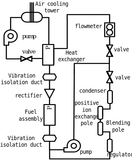
The experimental loop includes the primary loop (main loop), the secondary loop
(cooling loop), assistant loop and equipment cooling loop. The primary loop could simulate
the actual operating condition in nuclear reactor, and providing the uniform flow field to scour
the fuel assembly, as shown in figure 1. In figure 1, the regulating valve could regulate the
flow velocity scouring the fuel assembly, so that the scour velocity could remain in the scope
of 0~18 m/s; The heat exchanger was used to export the heat produced by the pump and
effect of the loop duct and groundsill’s vibration; The rectifier could ensure the scour flow
field be uniform, stabilize and parallel.
P
P
flowmeter
Heat exchanger
Vibration isolation duct
rectifier
Fuel assembly
pump
valve Air cooling
tower
valve pump
valve
condenser
positive ion exchange
pole Blending
pole
regulator Vibration
isolation duct
Fig. 1 the flow induce vibration experimental loop
In the experiment of the flow induced vibration, the pump produced large mount of heat
due to resistance. The cooling loop (secondary loop) was put up to reduce the water
temperature in the primary loop, as shown in figure 1. The cooling loop’s main equipments
included: heat exchanger, circulating pump, regulating valve and air cooling tower. The heat
exchanger could absorb the heat produced in the primary loop so as to reduce the water
temperature in the primary loop; The valve is used to regulate the flow rate in the cooling loop
to control the temperature of the primary loop; The air cooling tower is used to cool the
circulating water in the cooling loop and transfer heat to the air.
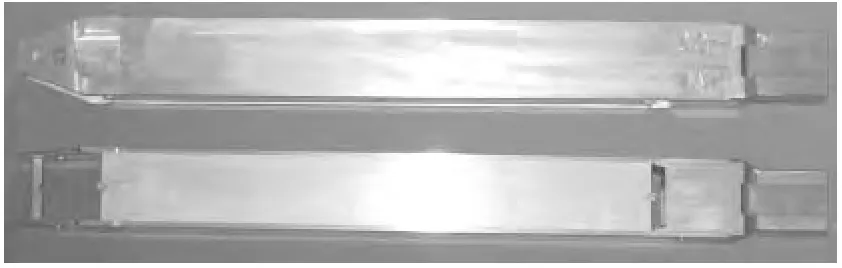
The fuel assembly used in the numerical simulation was a full-size assembly, which was
composed of 20 fuel plates with a gap of 2.28 mm. Figure 2 shows the planar fuel assembly’s
appearance. Each fuel plate was consolidated on the side panels. The side panel is shown on
the top of figure 2 out of the paper, and the border fuel plate is shown on the bottom of figure
2 out of the paper. All the fuel plates were fastened with a pectinate localizer. The lifting beam
was located at the inlet of the planar fuel assembly, which was used to fasten the side panels
and its function was to fasten the side panels and the fuel plates.
The velocity between the fuel plates could be acquired using the flowmeter and gap
velocity measurement equipment [3]. A quarter of flow field in the planar fuel assembly could be acquired through this way, and as the fuel assembly having the symmetry structure, the
whole flow field distribution could be acquired.
Fig. 2 the planar fuel assembly’s appearance
. Inherent vibration characteristic experiment
The heat density in the primary loop of the nuclear reactor is very high, so the heat must
be carried away by coolant quickly. The fuel assembly endures the scour of the coolant with
high velocity, so the performance of the fuel assembly must be very well, the performance
includes: intensity, rigidity, stability and reliability. The inherent vibration frequency is the
most important parameter to scale the structure’s vibration characteristic. The vibration
parameter and its corresponding inherent frequency and damp ratio in quiet air could be
acquired through inherent vibration experiment of the planar fuel assembly, which could
provide reference to the flow induced vibration of the planar fuel assembly. Table 1 shows the
first rank inherent frequency measurement results of the planar fuel assembly.
Through the inherent vibration characteristic experiment of the planar fuel assembly, it is
known that the inherent vibration frequency of the planar fuel assembly was different at
different directions, which was induced by the structure’s asymmetry. The corresponding
dump ratio of apiece inherent vibration frequency was very small, which showed that the
structure’s rigidity is relatively strong. The dump ratio decreased with the increase of the
corresponding inherent frequency, but the logarithm attenuation coefficient changed little
between 0.034~0.037, which showed that the absolute attenuation velocity of apiece
frequency components had little difference. The inherent frequencies and dump ratios of the
Table 1 the first rank inherent frequency of the assembly
Experiment method Vibration platform Experimental mode
Installation similar to
core state
In air
0.26g
In water
0.23g
Eliminating
the top
elastic frame
Put on the
sponge mat
evenly
upside Elastic support with gap freedom freedom
Boundary
condition
downside insert insert freedom
X direction 57.5 20.0 27.0 328.4
Inherent
frequency
(Hz) Y direction 62.5 27.5 34.5 353.0
. Flow field between fuel plates
The flow field scouring the planar fuel assembly was uniform. The water introduced into
the planar fuel assembly and passed the lifting beam, 20 parallel fuel plates and a nozzle, and
flow field in 19 flow channels was produced. The flow field between fuel plates was drawn
through experiments.
Figure 3 shows the velocity distribution in different flow channels, and figure 4 shows
the velocity distribution in the same flow channel. The experimental results showed that the
flow field distribution in the fuel assembly varied little with increase of the flow velocity. The
flow velocity decreased gradually from outside channel to inside channel, the velocity in the
middle flow channel was the least; the velocity decreased gradually from inside to outside in
single channel, and the velocity in the middle location was the most. This is because when the
water flow into the fuel assembly, it flows through the lifting beam firstly, and then reaches
the fuel plate, which is close to the lifting beam, and the lifting beam’s dimension is larger
than the flow channel’s dimension, and the lifting beam is parallel to the fuel plate, which
0 2 4 6 8 10
-40 -20 0 20 40
distance /mm
flow velocity /
(m/s) 7.3 m/s
6.7 m/s 5.6 m/s 5.0 m/s 4.1 m/s 2.7 m/s 0 2 4 6 8 10
-40 -20 0 20 40 distance /mm flo w velocit y /(m/s) 7.3 m/s 6.7 m/s 5.6 m/s 5.0 m/s 4.1 m/s 2.7 m/s
Fig. 3 the velocity in different flow channels Fig. 4 the velocity in the same flow channel
. Flow induced vibration experiment
Flow induced vibration may cause the damage of the planar fuel assembly, so it is
required to conduct full-size flow induced vibration experiment for the fuel assembly to
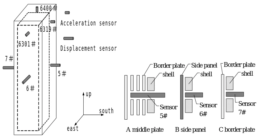
obtain the dynamic response of the assembly in the flow induced vibration. 6 sensors were
deployed in the fuel assembly for the experiment, as shown in figure 5, the acceleration
sensors were used to measure the vibration status of the assembly, and the displacement
sensors were used to measure the displacement of the middle fuel plate, border fuel plate and
side panel. Figure 6 shows the installation of the displacement sensors. Table 2 shows the
displacement of each vibration measurement point of the planar fuel assembly.
Acceleration sensor Displacement sensor 6400 6319 6301 6 5 7 east south up shell Sensor 5# Border plate shell Sensor 6# Side panel shell Sensor 7# Border plate
A middle plate B side panel C border plate
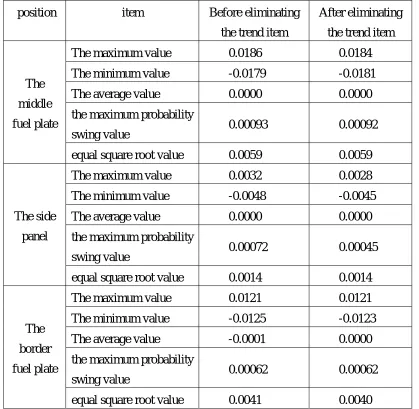
Table 2 the displacement of each vibration measurement point of the planar fuel assembly
position item Before eliminating
the trend item
After eliminating
the trend item
The maximum value 0.0186 0.0184
The minimum value -0.0179 -0.0181
The average value 0.0000 0.0000
the maximum probability
swing value 0.00093 0.00092
The
middle
fuel plate
equal square root value 0.0059 0.0059
The maximum value 0.0032 0.0028
The minimum value -0.0048 -0.0045
The average value 0.0000 0.0000
the maximum probability
swing value 0.00072 0.00045
The side
panel
equal square root value 0.0014 0.0014
The maximum value 0.0121 0.0121
The minimum value -0.0125 -0.0123
The average value -0.0001 0.0000
the maximum probability
swing value 0.00062 0.00062
The
border
fuel plate
equal square root value 0.0041 0.0040
The vibration swing of the planar fuel assembly was very small in rating condition in the
experiment. The vibration swing of the fuel plate was larger than the side panel, the maximum
vibration swing of the fourth fuel plate was 0.0186 mm, the maximum probability swing was
0.00093 mm, the breadth equal square root was 0.0059 mm. The border fuel plate correspond
maximum vibration swing was 0.0121 mm, the maximum probability swing was 0.00062 mm
and the breadth equal square root was 0.0041 mm.
Figure 7 shows the upstream and downstream average square root displacements. It
could be seen that the fuel plate had little displacement at low velocity of less than 6 m/s. The
vibration of the fuel plate pricked up with the increase of the flow, the swing of the middle
fuel plate was larger than the border fuel plate, and the swing of the border fuel plate was
plate was larger than the side panel, which showed that the fuel assembly’s main vibration
occurred on the fuel plates.
There was no large swing vibration of the flow elastic instability occurred in the flow
velocity scope of 0~18.8 m/s, so the critical flow velocity of the flow elastic instability was
not in the velocity scope of the experimental conditions.
0 0.05 0.1 0.15 0.2
0 5 10 15 20
velocity /(m/s)
dis
placemen
t /
0 0.1 0.2 0.3 0.4
0 5 10 15 20
velocity /(m/s)
displacement / m
m
a upstream b downstream Fig.7 the average square root displacement value
the middle fuel plate the side panel the border fuel plate
. Conclusions
1 The inherent frequency of each side of th e planar fuel assembly was in some scope
without a certain value. The planar fuel assembly’s inherent frequency has some difference at
different directions. The corresponding damp ratio of each rank inherent frequency of the
assembly was very little, and the damp ratio decreased with the increase of the corresponding
inherent frequency.
2 The flow velocity distribution was not uniform in different flow channels of the fuel
assembly, and the flow velocity was also not uniform in the same flow channel. The flow field
in the fuel assembly changed little with the increase of the flow velocity. The velocity in
different flow channels decreased gradually from outside to inside, and the velocity in the
middle flow channel was the least. The flow velocity in the same flow channel decreased
gradually from inside to outside, and the velocity in the middle position was the most.
3 The vibration swing of the planar fuel a ssembly was very small in rating condition in
the experiment. The vibration swing of the fuel plate was larger than the side panel. The fuel
plate had little displacement at low velocity of less than 6 m/s. The vibration of the fuel plate
border fuel plate, and the swing of the border fuel plate was larger than the side panel. The
maximum displacement was 0.3677 mm. The swing of the fuel plate was larger than the side
panel, which showed that the fuel assembly’s main vibration occurred on the fuel plates.
4 There was no large swing vibration of the flow elastic instability occurred in the flow
velocity scope of 0~18.8 m/s, so the critical flow velocity of the flow elastic instability was
not in the velocity scope of the experimental conditions.
Acknowledgments
The author acknowledges the sustentative fund of project 50325620 and project
10372050 provided by the National Natural Science Foundation of China.
References
[1] Hanliang BO, Zongbo CHI, Dezhong LI. The performance experiments and lift-span measurement of the hydraulic control rod driving system of 200 MW Heating Reactor. Beijing: the Institute of Nuclear and New Energy Technology, 1998.2-8
[2] Guowei WU. The nuclear reactor’s engineering design. Beijing: the Atomic Energy Publishing House, 1997.45~46