Abstract
BRALY, JOHN CHRISTOPHER. The Development of a Low-Cost and Robust Autonomous Robot Colony Using LEGO Mindstorms. (Under the direction of Dr. Edward Grant)
The late twentieth century marked the birth of urban search and rescue robots. The
act of rescuing victims from collapsed or damaged buildings is extremely dangerous for the
humans involved. After the attacks on the World Trade Center, researchers recognized the
need for small robots with limited capabilities to be used in conjunction with more advanced
robots for urban search and rescue. This research has developed a low-cost, autonomous
robot colony with limited sensor capabilities using the LEGO Mindstorms development platform. The study of this colony will provide insight into the group behavior of a
marsupial robot colony used for urban search and rescue.
A microphone sensor was developed to facilitate communication among the robot
agents that comprise the colony. The incoming analog signal was amplified using a standard
non-inverting operational amplifier configuration. This amplified signal was input into a
tone detection circuit. This circuit was designed to provide a digital output to the LEGO
robot if a single tone of a specific frequency was detected. Other frequency tones have no
effect on the circuit. Using this sensor, the robots could be controlled with different
frequency tones.
The task undertaken by the robots was a shepherding mission. The goal of the
sheepdog robot was to herd the sheep robot into a pen located at a fixed location. A helper
dog robot was added to assist the sheepdog when needed. The interaction, as well as
The Development of a Low-Cost and Robust Autonomous
Robot Colony Using LEGO
®Mindstorms
™by
JOHN CHRISTOPHER BRALY
A thesis submitted to the Graduate Faculty of North Carolina State University
in partial fulfillment of the requirements for the Degree of
Master of Science
ELECTRICAL AND COMPUTER ENGINEERING
Raleigh
2003
Biography
Acknowledgements
I would first like to thank my advisor, Dr. Eddie Grant, for allowing me to pursue this crazy idea of building something useful out of LEGOs®. Without his guidance and patience, this project could have never been completed. He allowed me to join the CRIM and pursue my interest in robotics without ever having worked with me. For that, I thank him dearly. I would also like to acknowledge my advisory committee, Dr. John F. Muth, Dr. Mark White, and Dr. H. Troy Nagle for their support throughout this process.
I also thank all of the members of the Center for Robotics and Intelligent Machines for their friendship and assistance. I consider myself lucky for being able to have worked with so many intelligent people. I would especially like to thank Kyle Luthy, Tim Slusser, and Leonardo Mattos for their unwavering support and the aid they have provided to me.
Table of Contents
List of Figures ... vi
List of Tables ... viii
Chapter 1 – Introduction ... 1
Section 1.1 – Project Motivation ... 1
Section 1.2 – Project Goals... 2
Section 1.3 – Thesis Outline ... 3
Chapter 2 - Literature Review... 4
Chapter 3 – The LEGO® Mindstorms™ Platform... 14
Section 3.1 – RCX and Programming... 14
Section 3.2 – Motors and Gearing ... 17
Section 3.3 – LEGO® Sensors ... 19
Section 3.3.1 – Light Sensor ... 20
Section 3.3.2 – Rotation Sensor... 22
Section 3.3.3 – Touch Sensor ... 23
Section 3.3.4 – Other LEGO® Sensors ... 23
Chapter 4 – Robot Communication ... 25
Section 4.1 – Infrared Light ... 25
Section 4.1.1 – RCX Infrared Transmitter/Receiver ... 25
Section 4.1.2 – Pulsing Infrared Light ... 27
Section 4.2 – Audible Sound ... 28
Chapter 5 – LEGO® Robot Colony... 30
Section 5.1 – Robot Colony Agents... 30
Section 5.1.1 – Robot Design and Sensors ... 31
Section 5.1.1.1 – Basic Robot Design... 31
Section 5.1.1.2 – Sheep... 33
Section 5.1.1.3 – Sheepdog... 35
Section 5.1.1.4 – Helper Dog... 37
Section 5.1.1.5 – Human Agent ... 38
Section 5.1.2 – Control Software... 39
Section 5.1.2.1 – Sheep NQC Control Software... 39
Section 5.1.2.2 – Sheepdog NQC Control Software... 40
Section 5.1.2.3 – Helper Dog NQC Control Software... 43
Section 5.2 – Microphone Sensor ... 44
Section 5.2.1 – Circuit Design ... 44
Section 5.2.2 – Sensor Construction ... 48
Section 5.2.3 – Interfacing the Sensor with the RCX ... 49
Chapter 6 – Experiments and Results ... 51
Section 6.1 – Robot Calibration... 51
Section 6.2 – Original Experiment... 55
Section 6.3 – Microphone Sensor Test ... 59
Section 6.4 – Assisting the Sheepdog... 60
Chapter 7 – Conclusions and Future Research ... 62
Table of Contents (continued)
Chapter 8 – References ... 65
Chapter 9 – Appendix ... 71
Section 9.1 – LEGO® Robot Colony ... 71
Section 9.1.1 – Sheepdog... 71
Section 9.1.2 – Sheep... 73
Section 9.1.3 – Helper Dog... 75
Section 9.1.4 – Field ... 77
Section 9.2 – NQC Source Code... 78
Section 9.2.1 – Sheepdog NQC Source Code... 78
Section 9.2.2 – Sheep NQC Source Code... 83
Section 9.2.3 – Helper Dog NQC Source Code... 87
Section 9.3 – Experiment Image Acquisition ... 89
Section 9.3.1 – Image Acquisition... 89
Section 9.3.2 – MATLAB Source Code ... 90
Section 9.3.2.1 defish_image_set.m ... 91
Section 9.3.2.2 – defish_image2.m... 92
Section 9.3.2.3 – make_real_robot_paths.m... 95
Section 9.3.2.4 – robot_movie_maker_ver4.m... 96
Section 9.4 – Parts List ... 98
Section 9.4.1 – Microphone Sensor Parts ... 98
Section 9.4.1.1 – Component List... 99
Section 9.4.1.2 – Component Datasheets... 100
Section 9.4.1.2.1 – Panasonic Microphone [39] ... 100
Section 9.4.1.2.2 – Texas Instruments Op-Amp [48] ... 101
Section 9.4.1.2.3 – New Japan Radio Tone Decoder [38]... 105
List of Figures
Figure 3.1 LEGO® Mindstorms™ RCX ...14
Figure 3.2 Disassembled RCX [44] ...15
Figure 3.3 LEGO® Mindstorms™ motor...18
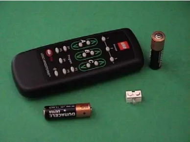
Figure 3.4 LEGO® remote and lamp from Ultimate Accessory Set ...19
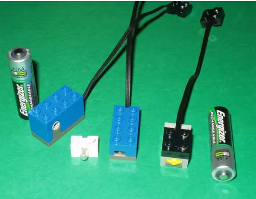
Figure 3.5 LEGO® Mindstorms™ sensors from left to right: rotation sensor, lamp, light sensor, and touch sensor ...20
Figure 3.6 Improving light sensor sensitivity. Use a small piece of black plastic to block the red LED emitter from the light detector (far left picture). Insert the plastic in between the red LED on the left and the light detector on the right (center picture). Put a 2x1 LEGO® Technic brick in front of the light sensor to secure the “filter” and allow the light detector to sense light through the hole (far right picture) [24]...21
Figure 4.1 Block diagram of infrared detector [8] ...27
Figure 4.2 Block diagram of infrared emitter [8]...28
Figure 5.1 Left and right rear drive motors...31
Figure 5.2 Light sensor scanning device...32
Figure 5.3 Front bumper ...32
Figure 5.4 Side bumper...32
Figure 5.5 Back corner wheels to aid when turning near a wall...33
Figure 5.6 Light bulb used to identify the dog...34
Figure 5.7 Infrared LED array on the sheep ...35
Figure 5.8 Three-channel active multiplexer ...36
Figure 5.9 Behavioral model of the sheep ...39
Figure 5.10 Behavioral model of the sheepdog ...41
Figure 5.11 Block diagram of corral task ...41
Figure 5.12 Behavioral model of the helper dog ...43
Figure 5.13 Circuit diagram of the microphone amplifier ...45
Figure 5.14 Internal components of tone detection chip [38] ...46
Figure 5.15 Tone detection circuit ...46
Figure 5.16 Circuit board layout for tone detection circuit (left), amplifier circuit (middle), and microphone circuit (right) ...48
Figure 5.17 Top and bottom view of fabricated tone detection circuit board (left) and amplifier and microphone circuit boards (right) ...49
Figure 5.18 Completed tone detection sensor...49
Figure 6.1 Distance the sheepdog traveled for a given amount of time...54
Figure 6.2 Sheepdog light sensor values at different distances from the sheep...54
Figure 6.3 Amount of time to travel for a specific light sensor value ...54
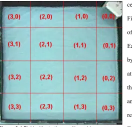
Figure 6.4 Field with starting position grid...56
Figure 6.5 Paths taken by sheep and sheepdog...57
Figure 6.6 Results of microphone sensor test ...59
Figure 9.1 Front side of sheepdog...71
Figure 9.2 Left side of sheepdog...72
List of Figures (continued)
Figure 9.4 Right side of sheepdog ...73
Figure 9.5 Front side of sheep...73
Figure 9.6 Left side of sheep...74
Figure 9.7 Backside of sheep ...74
Figure 9.8 Right side of sheep ...75
Figure 9.9 Front side of helper dog...75
Figure 9.10 Left side of helper dog...76
Figure 9.11 Backside of helper dog ...76
Figure 9.12 Right side of helper dog...77
Figure 9.13 The 8’ x 8’ field used to conduct experiments ...77
Figure 9.14 The pen used for experiments...78
Figure 9.15 Image acquired while conducting experiments ...89
Figure 9.16 Defished and cropped image ...89
Figure 9.17 One frame of the MATLAB movie showing two robots and the paths they have taken ...90
List of Tables
Table 6.1 Sheep and sheepdog experiment results...56
Table 9.1 Components used for the microphone circuit board ...99
Table 9.2 Components used for the amplifier circuit board...99
Table 9.3 Components used for the tone detector circuit board...99
Chapter 1 – Introduction
The study of cooperative animal societies helps to provide insight into group dynamics and behavior. By studying the foraging behaviors of fish, the mob behavior of whip-tail wallabies, or the organization of primate colonies, researchers gain an in-depth knowledge of animal behavior. Ants are one of the most studied biological systems. Their social organization, methods of communication, and decision-making are some of the most sophisticated of any biological society [3]. Studying different biological societies serves as a model for mobile robot societies. In fact, cooperative multi-agent robot society research was motivated by biological systems [31]. Many researchers have attempted to create robot societies that mimic animal societies.
Section 1.1 – Project Motivation
Mobile robotics research changed directions in the mid-1990s after two disasters stunned the world. The Kobe earthquake in January of 1995 and the Oklahoma City bombing in April of 1995 resulted in massive devastation and a tremendous loss of life. Robotics researchers recognized that rescuers needed help when searching for victims trapped in the rubble of collapsed buildings. The act of searching for victims is not only difficult, but also extremely dangerous. Rescue workers face the possibility of gas leaks, explosions, and further collapse. The use of mobile robots for urban search and rescue missions help reduce the risks faced by workers at the outset of the operation.
much of the search area. For this reason, many are investigating the possibility of using small “micro-rovers” in tandem with the larger robots for search and rescue missions. The larger robots will remain relatively unchanged except for having the smaller robots gather the sensory information. The larger robot also transports the micro-rovers to the rescue site. This cooperative group of mobile robots has been termed “marsupial robots” because it is similar to the way a kangaroo mother carries her young.
This research focuses on developing a marsupial-like robot colony using a low-cost, robust robot platform. Instead of concentrating on creating the larger robot, several micro-rovers are built to investigate ways of communicating with the team of robots. This thesis presents background information regarding the LEGO® Mindstorms™ platform used to develop the mobile robots. A description of the experiments performed on the colony and the results are then presented. Finally, potential future research areas are suggested.
Section 1.2 – Project Goals
The objectives of this thesis are to
1. Provide a complete description of the LEGO® Mindstorms™ platform used to develop the robot colony.
2. Investigate various communication schemes that can be used to provide instruction to the robot colony.
3. Describe the design and construction of the robot colony, including additional hardware and software used.
Section 1.3 – Thesis Outline
In Chapter 2, an extensive literature review is presented. Cooperative, multi-agent robot societies are discussed, as well as biologically inspired research, LEGO®
Chapter 2 - Literature Review
In 1948 and 1949, while investigating his theories about the nervous system, W. Grey Walter built two autonomous robots to help him understand the operation of animal brains. Each Machina speculatrix robot had a vacuum tube that simulated two interconnected neurons. These amplifier circuits connected two sensors, a photocell and a touch sensor, to the two motors [29] [50]. When the touch sensor was closed, one of the amplifier circuits oscillated, and the robot changed direction [29] [50] [51]. The two “tortoises” exhibited some intriguing behaviors, including the tendency “to explore the environment rather than to wait passively for something to happen” [50, pg. 126]. Other behaviors included the
attraction to moderate light, the repulsion when exposed to bright light, mutual recognition (the robots would “flock” together when there was no outside stimulus present), prioritizing tasks (i.e. avoiding an obstacle instead of moving toward a light), and the inclination to seek environments with favorable conditions (i.e. moderate light) [3] [50].
Walter then began to study whether or not his robots could learn. He attached a circuit, the Conditioned Reflex Analogue (CORA), to his original robots creating Machina docilis. CORA provided a link between either of the robot’s sensors (light or contact) with a sound stimulus. Using this circuit, Walter trained his robots to come by first blowing a whistle and then showing the robot a light. He then trained it move away from a loud sound by blowing the whistle and then triggering the contact reflex [29] [50] [51]. These
experiments with Machina speculatrix and Machina docilis provided the foundation for the study of robot-robot and human-robot interaction.
multiple mobile robot systems in the late 1980s [31]. In 1988, Fukuda and Nakagawa [17] proposed a robotic system that would be able to autonomously reconfigure its shape and software given a specific task. This system is comprised of individual autonomous “cells” that have a single function and a small amount of intelligence, much like the individual cells of the body. In the body, each cell works alone but can cooperate with other cells in the group to perform a specific task. Gerardo Beni [9] discusses the idea of creating an autonomous robotic system in which the individual robots work together to accomplish an explicit task. These simplistic robots do not have a central controller nor do they share memory, but when working together, they can accomplish complex tasks.
Throughout the 1990s, several research themes emerged for multi-agent systems. Some of the most common themes include foraging for items, performing tasks (assembly or disassembly), maintaining formations while moving throughout an area, surveillance,
transporting objects, path-planning, collision avoidance, and robot-soccer [3] [31]. Rybski and others [46] have developed a multi-agent system that can be used for reconnaissance and surveillance. The system is comprised of a few large robots and several small “scouts” that serve as the eyes and ears of the operation. The large robots function as supervisors, collect data from the scouts, and coordinate the behaviors of the scouts. Researchers in Brazil [42] have developed two robots that perform a box-carrying task without having to explicitly communicate (no data flow between robots) with each other. The determination of the robot’s role in the task is made by relying solely on local sensor data. The research has shown that this method of communication is just as effective as explicit communication. Other researchers have investigated dynamic role assignment of multi-agent teams for
of a team of robots that play soccer. This approach allows for the reduction of interference among team members, as well as determining their role (i.e. offense or defense) based on their location on the field. This eliminates the need for specialized players and allows all teammates to help each other if needed. Chaimowicz and others [12] also use dynamic role assignment for a group of robots that cooperatively search and retrieve objects scattered throughout the environment. This allows for adaptations to be made if an unexpected change in the environment occurs and results in improved overall efficiency. Lynne Parker [41] has investigated how cooperative team performance is affected by robot team member awareness when performing a puck-moving mission. Her research indicates that the awareness on team performance is a function of several factors, including team size, how well the effects of actions are sensed, the amount of work available for each team member, and the cost of executing redundant tasks. She has also developed ALLIANCE [40], a software architecture that “facilitates fault tolerant, reliable, and adaptive cooperation among small- to medium-sized teams of heterogeneous mobile robots, performing (in dynamic environments) missions composed of independent tasks that can have ordering dependencies” [40, pg 221]. The feasibility of this control architecture was demonstrated by performing a simulated hazardous waste cleanup with a team of mobile robots in the laboratory. The research indicates that ALLIANCE improves the team robustness by continually monitoring the sensors of a single robot and then adapting the robot’s response based on environmental changes that have occurred and the actions of its teammates.
systems are also more redundant, and therefore more fault-tolerant, than a single-robot system. If one robot fails, the others can still complete the task without any major problems. Also, with a team of robots, the sensor information of one robot can be shared with the others, allowing for more informed decisions to be made by individual team members. Finally, there is an improved system performance when several robots are used, allowing for divide and conquer techniques to be employed. With multi-agent systems, several “tasks can be completed considerably more efficiently overall for a wide range of tasks and
environments using groups of robots working together” [3, pg 359].
There are, however, several problems that can arise when using multiple robots [3] [34]. Interference can occur with too many robots and not enough work. Problems can also occur when numerous robots are being used in confined areas. Team members can
unintentionally interfere with each other in this situation. It is also difficult for a robot to know when it or another team member is being unproductive. Communication between team members is also a problem area with multi-agent systems. Specialty hardware, extra
processing, and more power are required for successful communication. Also, noisy
The multi-agent robot systems research that emerged at the end of the 1980s and continued through the mid-1990s was inspired by biological systems and “the collective intelligence demonstrated by social insects” [31, pg 7]. An ant colony provides a good example. The colony is comprised of hundreds of ants, each with a specific duty. Yet a group of these ants can work together to move a dead earthworm from one place to another [31]. Russell et al. [45] created a robotic system that replicates the way ants mark the trail between their nest and a food source (both ingoing and outgoing). Like ants, the robots in this system perform navigation tasks by leaving and detecting trails of volatile chemicals. The researchers suggest that this type of system could be used by a group of cleaning robots to mark an area of the floor that has already been cleaned. At the University of Strathclyde in Glasgow, Scotland, Lambert [28] and Russell designed and built autonomous robots to imitate the behavior of a sheepdog and a sheep. The primary goal of their project was to have the sheepdog herd the sheep into a pen located at an arbitrary location while
maintaining the natural behaviors of both the sheep and sheepdog.
software used to control the two robots. Finally, they were to operate over as large of an area as possible.
The behavioral model of the sheep consisted of three parts: graze, flock, and flee. First, the sheep would move within the field in a random way, thus appearing to graze. If the sheep detected the dog at a distance, it flocks towards other sheep if they are not close to the dog. If the dog moved too close to the sheep, it would panic and move away at full speed. The behavioral model of the dog is made up of four parts: finding the pen, locating the sheep, herding the sheep towards the pen, and funneling it into the pen. First, the dog would search for the pen. Once the pen was located, the dog would search for the sheep. When it was located, the dog moves towards the sheep. It would move around the sheep to a position where the sheep is between itself and the pen. This caused the sheep to move away from the dog and towards the pen. Once the dog had moved the sheep near the pen, it would the force the sheep into the pen.
Combining the biologically inspired multi-robot systems research of the mid-1990s and the need to help rescuers during urban search and rescue missions resulted in the
tether or a recharging station. It can also help the smaller microrover during its mission by acting as a leader or manager. The mother can collect the sensor data from the daughter robot and use it to make decisions that pertain to the task at hand. It can also serve as a communication relay station between the microrover and the human operator. Finally, the mother robot can rescue the daughter robot if it gets into trouble [34] [35] [37].
Traditionally, only highly trained individuals and dogs were used in USAR missions. However, the idea of using robots to help rescue survivors came about in 1995. On January 17, 1995, an earthquake centered near the area of Kobe and Osaka, Japan registered 7.2 on the Richter scale. This earthquake killed 5,100 people, injured 26,800 others, and caused approximately US$100 billion damage. Soon after the earthquake, the Tokyo Fire
Department’s Fire Science Laboratories began to develop a line of robots that could be used in urban search and rescue applications. On April 19, 1995, 168 people were killed and more than 500 people were injured in the bombing of the Alfred P. Murrah Federal Building in Oklahoma City, OK. John Blitch, a Masters of Science student of Robin Murphy at the Colorado School of Mines, served as a rescue worker. When he returned, he and Murphy, an expert researcher in the field of USAR, decided to focus their research efforts on developing robots that could be used to help urban search and rescue missions [14]. Others [26] also began researching the use of robots for urban search and rescue in the late 1990s. A
One of the major problems with USAR research is the lack of realistic field studies. Researchers at the University of South Florida have teamed together with the local fire department [10] [11] [14] [36] to test their robots in a staged search and rescue environment. However, these staged environments can only identify potential problems and validate hypothesized situations that may be encountered during an urban search and rescue mission. Unstaged USAR environments are needed in order to determine if the current research is moving in the right direction. After the attacks on the World Trade Center in New York City on September 11, 2001, robots were used in an actual search and rescue mission for the first time. Soon after the attacks, Blitch organized a group of robot researchers and
manufacturers to help with the search and rescue mission. The group was at the site for about four weeks, and found ten victims (more than 2% of all victims discovered). This experience helped to validate that the USAR research is moving in the right direction [10] [14].
There are several benefits of using robots, especially marsupial robot teams, for urban search and rescue efforts. Most importantly, rescue situations are extremely dangerous for those involved. There is a high potential for gas leaks, explosions, and further collapse. Robots can send environmental conditions of the search area, such as the presence of harmful gasses and seismic data, to rescue workers. Using robots can reduce the risks faced by humans at the outset of the rescue mission. Also, rescue workers must be very deliberate while searching for victims in order to remain safe. In some situations, workers might be required to leave an unstable site until it becomes safe to return. Robots can perform
Marsupial robots are particularly useful in search and rescue situations. A marsupial robot team is specifically designed for very small robots to be carried to a site by a larger robot. The size of the daughter robot allows it to move through small voids that larger robots and humans cannot fit into. Also, the daughter robot does not have to worry about sending sensory information back to the rescue workers. This is performed by the mother, resulting in the battery power of the daughter being used primarily for the search. Murphy’s
experiments show that a marsupial team can perform better than individual robots can when it comes to reaching destinations and arriving at these destinations quicker over longer distances. Murphy is also investigating using robots as part of the marsupial team that can change their shape depending on the environment, as well as the human-marsupial team roles during a USAR mission [35] [37].
Researchers in Japan [52] have performed experiments that evolve the morphology and controller of a LEGO® robot. Iversen et al. [25] present findings on the automatic
Chapter 3 – The LEGO® Mindstorms™ Platform
Previous research was conducted to determine the feasibility of using the LEGO® Mindstorms™ Robotics Invention System 2.0 as a platform for autonomous mobile robot development [8]. During this project, two mobile robots were created to mimic the behavior of a sheep and a sheepdog. The results of this research indicated that the LEGO®
Mindstorms™ could serve as acapable platform to use for the design and construction of mobile robots without having to make any modifications to the original system. The capabilities and limitations of the LEGO® Mindstorms™ platform will be discussed in the following section.
Section 3.1 – RCX and Programming
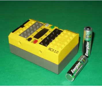
At the heart of the LEGO® Mindstorms™ Robotics Invention System is the robotic command explorer, or RCX (Figure 3.1). Each RCX is powered by a total of six AA
batteries. The major components of the RCX are the Hitachi H8 microcontroller with 32 KB of RAM, three output ports used to power the motors, three input sensor ports, and a liquid-crystal-display (LCD) screen. It also contains an infrared transmitter and receiver, which can be used to communicate with the base station plugged into a computer or another RCX block [44] [49]. A Stanford University graduate student, Kekoa Proudfoot, was the first person to disassemble the RCX and fully document the internal components [49]. A picture of Kekoa’s disassembled RCX is shown in Figure 3.2.
The lack of sensor input and motor output ports are the most serious limitations of the RCX. Only three sensors can be used with the RCX at one time. In order to build a
functional autonomous robot, more than three sensors are often needed. However, the lack of motor ports does not hinder development as much. For most applications, the three motor output ports will suffice. For most applications, more than three motors will result in too much weight, and the robot will not be able to move very well. To allow for more than three sensors to be connected to the RCX, several sensors can be connected to the same port by multiplexing them together. By changing the sensor type from light to touch and then back
to light, the RCX can cycle through the sensors. This action is similar to cycling though outputs of a standard multiplexer using a clock. As the RCX changes from one sensor to another sensor, it does not only just switch the signal to the sensor, but it also switches the power to the sensor off. This results in a conservation of battery power, since only one of the
multiplexed sensors will be on at a time [1]. Other similar expansion techniques for more input and output ports have been found in online literature [20].
Another drawback is the limited amount of onboard memory (32 KB), of which about half is taken up by the firmware. The firmware is used to interpret the downloaded programs and execute the processor machine code [49]. A total of five programs can be loaded onto the RCX at one time. However, these programs can be no larger than 6 KB and must be limited to the use of up to 32 variables [27]. This limited amount of memory for a program is not a severe drawback since typical RCX programs tend to be only hundreds of bytes long [5]. This shortcoming does not prevent the development of autonomous mobile robots.
The visual programming environment for the LEGO® Mindstorms™ Robotics Invention System 2.0 poses a slight problem when developing robots using this platform. In order to write a program, blocks are arranged using the supplied PC software [49]. This method of programming may be perfect for the audience the product was designed for (children ages 12 and up). It is, however, difficult to implement advanced algorithms using this technique. The supplied programming environment does not support recursion and nested control constructs [27]. Fortunately, alternative languages and cross compliers have been developed for more advanced programming. These options include Not Quite C (NQC) [5] [6], pbForth (a variant of Forth) [23], leJOS (JAVA based) [47], Visual Basic [22], Visual C++ [7], and Ada [16].
For this project, all code was written in the NQC programming language (Beta
and understood by the RCX firmware. Using this technique to write programs, rather than the LEGO® visual programming technique, gives the user more control over the RCX hardware [49].
NQC supports traditional C function definitions and commands (such as for and while loops) with additional commands designed specifically for the LEGO® Mindstorms™ kit. These functions include commands to define sensor ports, to define motor directions and power levels, to play various sounds, and to send and receive simple messages and serial data using infrared [6]. The major drawback to using infrared communication between two different RCX blocks is that the message cannot be received from all directions. In order for an RCX block to receive a message, its receiver must be pointing directly at the transmitter of the other RCX block that is sending the message. There is also extremely large power consumption when sending a message, resulting in a battery lifespan much shorter than normal.
One aspect of NQC that is different from traditional C is the task code block. Since the RCX supports multi-tasking, “an NQC task directly corresponds to an RCX task” [6, pg. 50]. The RCX can support up to 10 tasks running simultaneously, including main, which is a task in NQC rather than a function as it is in the C programming language [6]. Tasks have a distinct advantage over traditional functions because, once started, they run continuously until a stop command is issued. Functions only execute once when called, making tasks more convenient for procedures that must run constantly.
Section 3.2 – Motors and Gearing
built. The Robotics Invention System contains numerous gears of varying sizes that allow for many different ways to “gear up” (increase rotational speed) or “gear down” (decrease rotational speed) the motor. It also contains several unique LEGO® blocks that can be used with the motors and gears to create an assortment of moving parts.
The two motors (one is shown in Figure 3.3) included effectively provide the
necessary power needed to develop a functional LEGO® robot. Unfortunately, the LEGO® Mindstorms™ kit only comes with two motors, which makes it difficult to create more complex robots. Individual motors, however, can be purchased if they are required [43]. The motors can be driven forward or backward in the on mode, not move at all in the off mode, or be allowed to “coast” in the floating mode. The floating mode is synonymous to neutral for an automobile. Each motor can operate at one of eight power levels. The RCX uses pulse-width modulation to create the intermediate power levels using a digital signal. Varying the widths of the pulses creates the intermediate power levels. The RCX sends pulses every 8ms with the width of the lowest power level being 1ms and the width of the highest power level being 8ms. The motor is constructed such that an internal flywheel is used to keep the motor spinning until the next pulse is supplied [5].
In 2002, LEGO® upgraded the motors supplied with the Robotics Invention System. Due to the fact that some of the kits were purchased prior to the change, the new (LEGO® part number 43362) and old (LEGO® part number 71427) motors will be discussed. The two motors are almost identical, but there are slight differences. Most noticeable is the
weight of the two motors. The pre-2002 motor weighs about 42 grams as compared to about 28 grams of the new motor. This decrease in weight will help when larger, more complex robots are being developed. Another less noticeable change is the addition of a PTC resistor that protects the motor from over-current by increasing the resistance if the temperature rises, thus limiting current. Based on Phillipe Hurbain’s experiments, the old motor performs slightly better, but the weight of the new motor can justify its use [24].
Section 3.3 – LEGO® Sensors
The following section describes the sensors included in the LEGO® Mindstorms™ Robotics Inventions System and the Ultimate Accessory Set. The usefulness of the sensors will be discussed along with ways to improve the
effectiveness of the sensors. In addition to the extra sensors, the Ultimate Accessory Set also contains a remote control, a LEGO® lamp (Figure 3.4), and extra LEGO® building materials. The LEGO® lamp does not produce much light and is not very useful in a lit room. It might, however,
be useful if the robot is operating in a dark environment. The remote control can be used to manually drive the motors, send a message to the RCX, or select which of the five programs to run. It is particularly useful since the robot can be started from a distance and prevents the user from getting in the way. The infrared receiver on the RCX must be pointed at the remote control in order for the remote to work.
Figure 3.4 LEGO® remote and lamp from
Section 3.3.1 – Light Sensor
The two major components of the LEGO® light sensor (Figure 3.5) are a red light emitting diode (LED) and a phototransistor. The phototransistor responds to the amount of incoming light, whether it is the amount of light being produced by a source or the amount of reflected light produced by the red LED [5]. Because of these two components, it is one of the most versatile LEGO® sensors. For example, it can be used on a robot to measure the
amount of ambient light in a room and perform various tasks
accordingly. It can also be used to determine the distance from a
particular light source (by measuring the amount of incoming light) or the distance to an object (by measuring the amount of reflected red light). However, measuring the distance to an object using the light sensor is not very effective unless the object is very close to the sensor. Finally, it can be used as a sensor that detects different colors by measuring the amount of reflected red light produced by the LED, since different colors reflect a different amount of red light.
If the red LED is not needed for the desired application, it can be “eliminated” to increase the sensitivity and performance of the light sensor. The light sensor can be disassembled and the red LED can be physically removed, resulting in improved
performance [2] [20]. This method is not recommended since permanent damage to the
structure of the sensor will occur, and possible damage to the sensor circuitry could result, rendering it useless. Another method that does not require any disassembly of the sensor has been performed [24]. Inserting a tiny piece of black plastic between the red LED and the phototransistor effectively blocks the red light and prevents it from being detected by the phototransistor. A 2x1 LEGO® Technic block can then be placed in front of the light sensor to secure the plastic. A small piece of electrical tape might be required to attach the plastic. Pictures illustrating this procedure are shown below in Figure 3.6.
With this configuration, the light sensor is not as susceptible to the effects of ambient light. It also makes the sensor extremely directional by restraining the detection of incoming light to the light that enters through the hole in the Technic brick. Tests have shown that when using this design, infrared light can be detected at distances up to twelve feet with the room lights on. This is quite impressive when compared to the results achieved when using standard cadmium sulfide (CdS) photoresistors.
One important factor to remember when using the light sensor is that the robot will need to be calibrated each time it is used. Each environment has a different amount of ambient light. Even if a Technic brick is placed in front of the sensor as shown above,
calibration might be required in order to work properly. Also, the light sensor requires power to operate. This means that as the batteries become weaker, the power supplied to the sensor decreases. The decrease in power will also result in the need for recalibration [5].
Section 3.3.2 – Rotation Sensor
The LEGO® rotation sensor (Figure 3.5) is not included in the Robotics Invention System. It comes in the Ultimate Accessory kit, or it can be purchased separately from LEGO®. This sensor measures the amount of rotation relative to a base position. The base position is defined, by default, as the position of the sensor when the program is started. However, a special command can be issued during operation to change the base position from the default position to the current position of the sensor [5].
The base position of the sensor is given the value of zero. After one complete revolution, the value of the sensor is 16, which corresponds to 22.5° per count. To increase the accuracy of the measurement, gear reduction can be used [5]. The sensor also counts down. For example, if the sensor completes one complete revolution by rotating in one direction (i.e. clockwise), the value will be 16. If it then completes one revolution in the opposite direction (anti-clockwise), then the value of the sensor will be zero. If it then makes another revolution in the anti-clockwise direction, the value of the sensor will be -16. The rotation sensor ranges from -32767 to +32767 [19].
analysis to determine exactly how it works, has determined that if a capacitor is added to the circuit, the sensor no longer skips values at low speeds [24]. An easier way to remedy this problem is to put the sensor on the shaft of the motor before any gear reduction is added. By doing this, the motor speed can be set high enough so the sensor does not skip any values. Gear reduction then can be added to increase the accuracy of the sensor. This method does not risk damage to the sensor by attempting to take it apart.
Section 3.3.3 – Touch Sensor
The LEGO® touch sensor (Figure 3.5) is the simplest of all the LEGO® sensors. When the button on the front of the sensor is not pressed, the circuit is open and the output value is LOW. The output value changes to HIGH when the button is pressed and the circuit is closed. These sensors can be connected to the same input port in a variety of ways to create either an AND configuration or an OR configuration. If connected in the AND configuration, two LEGO® lamps can be used to determine which touch sensor has been pressed [20]. When the sensors are connected in the OR configuration, the RCX cannot distinguish which sensor is being pressed [5]. The touch sensors can be used to construct “bumpers” that will result in the robot performing a certain task, such as reversing its direction, if it runs into an obstacle.
Section 3.3.4 – Other LEGO® Sensors
the RCX, including a humidity sensor, a pH sensor, a pressure sensor, and a sound level sensor [30].
Chapter 4 – Robot Communication
One if the most challenging aspects when developing a cooperative robot team is establishing a communication link between team members. The major problem is that a communication system is not reliable at all times. For example, noisy channels can cause a robot to miss a message or interpret it incorrectly. Also, in some environments, electronic countermeasures may be used to block communications between team members.
Malfunctioning receivers can also cause a robot to miss a message. Other important factors regarding a communication system are range, signal strength, and type of communication (direct communication or communicating through observation) [3]. In this chapter, the two primary techniques of establishing a communication link between the LEGO® robots that were investigated are discussed.
Section 4.1 – Infrared Light
Two methods of infrared communication between robots were explored. The first method consisted of using the infrared transmitter and receiver on the RCX. The second method was to pulse infrared light at different frequencies, each corresponding to different messages.
Section 4.1.1 – RCX Infrared Transmitter/Receiver
The basic idea behind this method of communication is each numbered message corresponds to a different instruction. With 255 possible messages (since the default value for no received message is zero), many different instructions can be given to the robots. Another benefit to using this communication scheme is that no additional hardware or
software is required. The RCX has the ability to send and receive infrared messages by using predefined NQC functions.
Unfortunately, there are major drawbacks to using this communication scheme. First of all, in order to receive a message, the robot must point the receiver directly at the
Section 4.1.2 – Pulsing Infrared Light
By transmitting infrared light at different frequencies, different messages can be sent by changing the frequency of the transmitted signal. When the robot detects a signal of a specific frequency, the instruction associated with that frequency could then be executed. Detection of the infrared signal can be accomplished by building an array with several detectors designed to sense infrared light of a specific wavelength. Each array element would detect a different wavelength, and thus correspond to a different instruction. A block diagram of this detection scheme is shown in Figure 4.1. In order to tell which array element
was sensing the signal, the output of each element would be sent to a multiplexer before being interfaced with the RCX. If a multiplexer is used, a clock is required to cycle through each input. Either a 555-timer circuit or RCX sensor input will provide an adequate clock for the multiplexer. In order to use the RCX sensor input as a clock, the sensor type must be changed from touch to light and back to touch over a pre-determined duration. The only problem with using this configuration is that two sensor inputs would be used, leaving only one for the remaining sensors. For this reason, the more desirable configuration to use is the 555-timer circuit.
Infrared Detection Array with N elements
Infrared signal with frequency fo
N N:1 Analog Multiplexer RCX Sensor Input 2 RCX Sensor Input 1 Hz 555-timer Circuit
Use either the 555-timer circuit or RCX to generate a clock
The easiest way to transmit an infrared signal at a specific frequency is by using the 555-timer, as shown below in Figure 4.2. The frequency of the output signal can be adjusted by changing R1, R2, or C1. The frequency is
related to these circuit elements by
1 2 1 2 ) (
44 . 1
C R R f
+
= [8]. The obvious
problem is that in order to change the emitted frequency, the circuit elements have to be changed. To make it simple to change the frequency, R2 and C1 should remain
constant while R1 should be adjustable.
This circuit configuration still requires an
operator to change the emitted frequency. Therefore, it cannot be used for robot-to-robot communication. As with the RCX infrared transmitter, this infrared transmitter must be aligned with the detector in order to receive the signal. For this reason, as well as the inability to send signals at different frequencies automatically, this method is not used.
Section 4.2 – Audible Sound
The second technique for establishing a communication link between robots is by using audible sound. The major advantage to using sound over infrared light is that the sound can be detected from any direction, especially when using an omnidirectional microphone. In addition, if there is an object blocking the infrared signal, the receiver will not detect the signal. However, this is not the case with an audible sound signal. The microphone can be orientated away from the sound source and still detect the sound.
the RCX has sound generating capabilities. The RCX can play tones of a specific frequency and duration using NQC commands [6]. This prevents the need for additional hardware required to generate tones. It also allows for the robots to communicate with each other instead of just having a human operator issuing instructions.
There are a few drawbacks to using sound. Weak signal strength or noise could cause problems when receiving the sound signal. However, with proper amplification and filtering, these problems can be reduced significantly. Also, in hostile environments, audible sound used to communicate between robots will not prevent the robots from being detected by the opposition. Therefore, it is not a viable option for robot-to-robot communication.
Chapter 5 – LEGO® Robot Colony
The robot colony developed for this project stems from previous research that
resulted in the creation of LEGO® robots that mimic the behavior a sheep and sheepdog. For that project, the goal of the sheepdog was to locate the sheep and herd it into a pen. Every movement made by the dog depended on its orientation relative to the sheep and the pen. The overall “thought process” of the dog was to move around the sheep such that the sheep was between itself and the pen. Once this occurred, the dog would then attempt to force the sheep into the pen. The pen is located in the corner of an 8’ x 8’ “field” enclosed by black walls. The new robot colony consists of two additional agents, as well as the sheep and sheepdog. While the overall task of the robots that comprise the new colony remains the same (for the sheepdog to force the sheep into the pen), the major objectives of this project are quite different.
Section 5.1 – Robot Colony Agents
Section 5.1.1 – Robot Design and Sensors
This section provides an in-depth description of several design issues that were present during the development of this robot colony. For the most part, the basic design of all three robots is the same. There are, however, some differences among the three. The basic design of the robots will be presented first, followed by specific details of each robot.
Section 5.1.1.1 – Basic Robot Design
For each robot, two motors located at the rear are used to drive and steer the robot. The drive motors are shown in Figure 5.1. For this application, the gear ratio is 1:1. No special gearing configuration was required for this design. By rotating the motors the same direction, the sheep will move either forward
or backward. If the motors are rotated in opposite directions, the robot will effectively turn left or right. This method of “turning” the robot actually causes it to spin. In fact, it is based on the way a tank turns. The original design included tank treads, but the weight of
the robot increased with the addition of extra components and resulted in difficulties with turning. For this reason, the tank treads were removed. Since there is no caster on the robot, the two front wheels have no tires. By not putting tires on the wheels, they will slide along the floor when the robot spins, resulting in an effective method of turning the robot.
A third motor is used to rotate a LEGO® light sensor on the sheep and sheepdog. The light sensor is attached to a shaft that is “connected” to the motor shaft using a worm gear. This allows the motor to rotate at high speeds, while rotating the light sensor at a much
slower speed. A picture of the scanner is shown in Figure 5.2. The LEGO® rotation sensor is mounted on the shaft of the motor. It monitors the position of the light sensor. Approximately 4.25 rotations by the motor correspond to rotating the light sensor by 180º. By having the rotation sensor mounted on the motor shaft before any gear reduction, better resolution and less error are achieved.
One of the problems that occurred frequently while running experiments were the robots kept getting stuck along the walls and with each other. The walls are comprised of several 29.5” x 1.5” x 9” (L x W x H) boards attached together. In some places, the wall sections do not come together flush. A front bumper with wheels was added to ensure that the robots would not get stuck at these places if they ended up along the wall. A picture of the front bumper is shown in Figure 5.3. Left-side and right-side bumpers (Figure 5.4) were added to prevent the robots from getting caught on each other. These bumpers run along the entire
Figure 5.3 Front bumper
Figure 5.4 Side bumper
Figure 5.2 Light sensor scanning device
Motor Light Sensor
Rotation Sensor
length of the robot and protect the wheels of the robots. The addition of bumpers around the robots significantly reduced the number of times the robots became stuck. These bumpers serve as a barrier around the robot and are not part of any sensor. Occasionally, the back of the robots would become stuck on the wall if they attempted to turn while in contact with them. In order to remedy this problem, wheels were added to the back corners of the robots. The addition of these wheels allows the robots to slide along the walls if they run into them while turning. Figure 5.5 shows these wheels on the robot.
Section 5.1.1.2 – Sheep
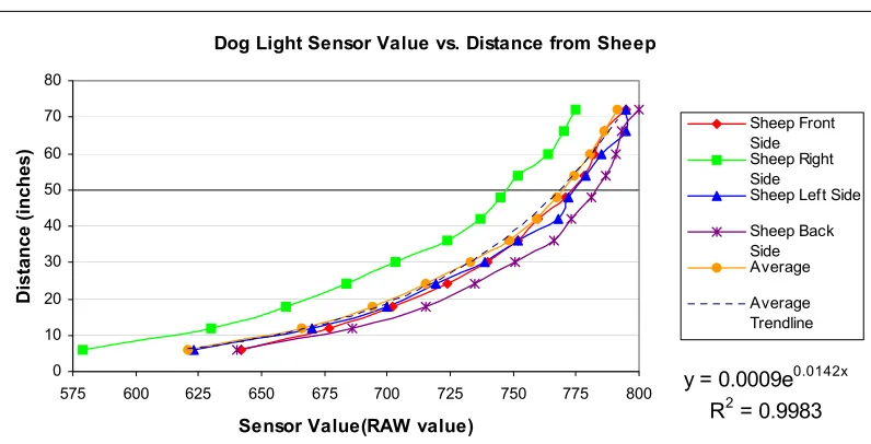
There are three sensors used on the sheep. The LEGO® light sensor is used to detect both the wall and the sheepdog. It is set to output the raw (0 to 1023) values when measuring light. The sensor value approaches zero as the amount of light detected increases. Since the walls are black, the light sensor will read a high number (greater than 900) when it is close to a wall. When the dog is near, the light sensor will detect the light mounted on the dog and read a lower number (less than 720).
The location of the light sensor is critical for detecting the sheepdog. To reduce the effects of ambient light on the sensor, a 2x1 LEGO® Technic block was placed in front of the sensor. This makes the light sensor extremely directional by only allowing light to enter through the hole in the Technic brick. Since this is the case, the light on the sheepdog must be at the same height as the light sensor on the sheep. Otherwise, the sheep would not be
able to “see” the dog. It is not vital that the sheep recognize the dog from across the field. The sheep is only concerned when the dog is in close proximity. For this reason, a Maglite flashlight bulb is used to identify the sheepdog. Figure 5.6 shows the Maglite flashlight bulb used to identify the dog.
The second sensor used is the LEGO® rotation sensor. This sensor is used to determine the direction the light sensor is pointing relative to the front of the sheep. The information provided by the sensor is used to determine which direction to move away from either the wall or dog. It is also used to determine when the sensor has rotated approximately 180º. Initially, the light sensor is pointing toward the front of the sheep, and the rotation sensor reads zero. While the light sensor is scanning, if the rotation sensor reads a value that corresponds to ±180°, it will cause the light sensor to stop and rotate in the opposite
direction. This prevents the wire connecting the sensor to the RCX from becoming wrapped around the rotating shaft. The rotation sensor also helps determine on which side of the sheep the dog or wall has been detected. For example, if the sensor reads a negative value (other than the value corresponding to -180°), the light sensor is pointing toward the left side of the sheep. Conversely, if the sensor reads a positive value (other than the value equivalent to +180°), the light sensor is pointing toward the right side of the sheep. By using the value of the rotation sensor, the sheep know which way to turn so it can move away from any trouble.
Section 5.1.1.3 – Sheepdog
The sheepdog uses four sensors to complete the task of herding the sheep into the pen. Like the sheep, it has a scanning device with a light sensor mounted on a rotating shaft. A rotation sensor is used to monitor the position of the light sensor. However, this light sensor is used to find the pen, and not used for detecting walls or the sheep. The location of the light sensor is critical in order for the dog to locate the pen. The light sensor must be at the same height of the infrared array mounted on the pen or the dog will not be able to herd the sheep into the pen. An array of infrared LEDs is used to identify the pen because the dog needs to be able to find the pen from any position in the field. The dog is also equipped with same bumpers that the sheep has. The front bumper has three wheels that prevent the robot from becoming stuck along the wall, and the side bumpers run along the length of the robot. There are also back corner wheels that facilitate turning if it is along the wall.
The second light sensor on the dog is used to detect the sheep and walls. Unlike the light sensor used to detect the pen, this sensor does not rotate. Since all three motor outputs are being used, this sensor must remain fixed. In order to search for the sheep using this sensor, the dog spins in a circle until the light sensor detects the infrared LED array (shown
in Figure 5.7) mounted on the sheep. This array of ten infrared LEDs is positioned on the sheep such that they are at the same height as a light sensor on the sheepdog. Infrared LEDs, rather than light bulbs, are used because the dog needs to be able to identify the sheep from across the field. This
technique of detecting the sheep has proven to be effective since tracking the sheep is not required. Once the sheep has been found, the dog immediately moves to a location based on its distance from the sheep and orientation relative to the pen. For this reason, the pen, rather than the sheep, must be tracked at all times. The final sensor used by the dog is a tone detection sensor. This sensor is used to listen for a specific frequency tone. When the dog hears this tone, it will stop its current task and perform different, predefined task. A detailed discussion regarding the design of this sensor is presented later in this chapter.
With only three sensor input ports and four sensors being used, there is a slight problem. Several hobbyists [20] have devised numerous ways of overcoming the problem of a lack of sensor inputs. One solution is to use a multiplexer so multiple sensors can be connected to the same port. A three-channel active multiplexer from Mindsensors Robotics [1] was used to allow the dog to have four sensors. The term “active” implies that power is required to operate each sensor (i.e. rotation, light, etc.). A picture of the Mindsensors Robotics multiplexer is shown in Figure 5.8.
This simple multiplexer consists of one output port and three input ports. The output port connects the multiplexer to an RCX sensor input port. The three input ports are used to connect the sensors. A circuit diagram of the multiplexer is shown in the Appendix. For this application,
only two sensors (both light sensors) are connected to the multiplexer. In order to cycle through each output of a multiplexer, a clock is required. Switching the sensor type of the input port from light to touch and back to light will create a clock. Because the light sensor
requires power to operate and the touch sensor does not, changing sensor types effectively creates a clock that can be used to cycle from one input to another. An interesting feature of this multiplexer is that it is not necessary to sequentially cycle through inputs. For example, Channel 3 can be selected after Channel 1 has been selected without having to read Channel 2. One benefit of using this multiplexer is that only one channel receives power at a time. For instance, if it is desired to switch from Channel 2 to Channel 3, power will only be applied to Channel 3 once the switch has occurred. This results in the power requirement of only one sensor when using the multiplexer regardless of the amount of sensors connected to the multiplexer. The one drawback is that only one of the possible three sensors can be used at a time. If a sensor must remain on for the entire mission, it cannot be connected to the RCX via the multiplexer. The multiplexer allows for a larger sensing suite onboard the robot, however, only a total of three sensors can be used at once.
Section 5.1.1.4 – Helper Dog
causes a few problems in regards to decision making, but they can be overcome because of the role the helper dog plays during this mission. The microphone sensor is used to listen for a signal instructing the dog to help the sheepdog with corralling the sheep. This sensor will be discussed in detail later in this chapter.
Like the sheep and sheepdog, there are also bumpers present on the helper dog. The front bumpers with wheels help keep the dog from getting stuck on the wall. The side bumpers prevent the wheels of the robots from becoming caught on each other. There are also wheels mounted on the back corners of the robot to facilitate turning when near a wall.
The helper dog uses a Maglite flashlight bulb in the same manner as the sheepdog. The light bulb is placed at the same height as the light sensor on the sheep. When the sheep comes close to the helper dog, it will run away. The sheep has the identical reaction to the helper dog as it does with the sheepdog. Again, it is not important that the sheep see the helper dog from anywhere in the field.
Section 5.1.1.5 – Human Agent
Section 5.1.2 – Control Software
In this section, the software used to control the robots will be discussed. Each robot was programmed using the Not Quite C (NQC) programming language developed by Dave Baum. This language was chosen because of the researcher’s familiarity with the C
programming language. The NQC code for each robot is provided in the Appendix.
Section 5.1.2.1 – Sheep NQC Control Software
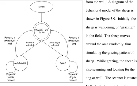
The behavioral model of the sheep consists of four major components: look for the dog or wall, randomly move around in the field, run away from the dog, and move away
from the wall. A diagram of the behavioral model of the sheep is shown in Figure 5.9. Initially, the sheep is wandering, or “grazing,” in the field. The sheep moves around the area randomly, thus simulating the grazing pattern of sheep. While grazing, the sheep is also scanning and looking for the dog or wall. The scanner is rotated 180° clockwise, and then it is rotated 360° in the counterclockwise direction. Once the light sensor has finished this rotation, it reverses its direction of rotation and completes another 360° rotation. This process is repeated unless the dog or a wall is detected. Both actions (scanning and
Figure 5.9 Behavioral model of sheep WANDER and
SCAN
PANIC START
AVOID WALL If a wall is
detected
wandering) are defined as tasks and they occur simultaneously. Once started, they will continue unless the stop command is issued.
When the sheep detects either a wall or the dog, it will stop grazing and perform the appropriate action depending on what has been noticed. If the sheep encounters a wall, it will calmly move away from it and then resume with wandering and scanning. However, if the sheep detects the dog, it will panic and run away. Both of these actions are accomplished in similar manners. First, the wander task is stopped, and then the corresponding function that will move the sheep away from the wall or dog is called. The direction the sheep will move depends on where the wall or dog is detected. For example, when the wall or dog is detected on the left side of the sheep, it will spin clockwise (to the right) and then move away from the wall or dog. The major difference with these two actions is the speed at which the sheep moves away. It treats the wall as a fence and calmly moves away from it. The sheep, however, fears the dog and runs away when it is detected. Both maneuvers are repeated until the sheep is at a safe distance from either one. The sheep then returns to grazing and
scanning.
Section 5.1.2.2 – Sheepdog NQC Control Software
sheepdog becomes stuck, a procedure is attempted to free the sheepdog. If the angle sensor does not move over a specified amount of time, the sheepdog will assume it has become stuck. It will then move backward and attempt to free itself.
The corral task is made up of five functions. A block diagram of the corral task is shown in Figure 5.11. The first action undertaken by the
sheepdog is finding the sheep. The dog uses the fixed light sensor to “look” for the sheep. It spins around until the infrared light emitted from the array mounted on the sheep is detected. Once the sheep has been detected, the sheepdog stops spinning. The dog then
START
CORRAL and AVOID WALL
Repeat if wall is detected Resume if away
from wall Repeat until the
sheep is in the pen
If a wall is detected
Move away from wall If a tone is
detected
Repeat until in front of pen
Move towards pen
STOP
When in front of the pen
Figure 5.10 Behavioral model of sheepdog
CORRAL
Locate the sheep
Move towards the sheep
Locate the pen Determine distance
away from sheep
Turn Repeat until sheep
is in the pen
determines its distance from the sheep based on the strength of the light signal detected. This distance will determine how far the sheepdog should travel before repeating the corral task. Using the light sensor mounted on the rotating shaft, the dog then searches for the pen. Once the pen has been found, the position of the light sensor is recorded and used to help
determine how the sheepdog should approach the sheep. Based on the orientation of the light sensor, the dog will spin either clockwise or counterclockwise. This is performed with the intention of having the dog move to one side of the sheep rather than directly at it.
Eventually the dog will move into a position such that the sheep is between itself and the pen. When this is the case, the dog will not need to turn before traveling toward the sheep, and it can move directly towards the sheep. The final action that is performed in the corral task is moving toward the sheep. Based on the distance to the sheep that was determined earlier, the dog will move forward for a corresponding amount of time. The task is then repeated until the sheep has been corralled into the pen.
Section 5.1.2.3 – Helper Dog NQC Control Software
The behavioral model of the helper dog is not complex. It has three parts: to wander around the field, to avoid walls, and to help the sheepdog corral the sheep. A block diagram of the behavioral model of the helper dog is shown in Figure 5.12. Initially, the helper dog wanders around the field. While it is moving in the field, if a wall is detected, it will stop,
move away from the wall, and then resume its movements. During the time the helper dog is moving in the field, it is not attempting to detect the sheep, sheepdog, or pen. Since its light bulb will be on, the helper dog should not have a problem with getting stuck on the sheep. If it gets too close to the sheep, the sheep will detect the light and move away from the helper dog. There could be some problems with the sheepdog, since the helper dog cannot see it. However, since the sheepdog is tracking the sheep and the sheep will avoid the helper dog, the sheepdog should also avoid the helper dog.
If the microphone sensor on the helper dog detects a tone, it will stop “wandering” and begin to help corral the sheep. The helper dog will position itself such that the sheep is
WANDER
MOVE where both SHEEP and PEN are detected START
AVOID WALL If a wall is
detected
If a tone is detected
Repeat if wall is present Resume if away
from wall
WAIT
Repeat if a tone is detected
between itself and the pen. If both light sensors detect the sheep and the pen, the helper dog will know the sheep is between the pen and itself. Once the helper dog has reached this position, it will stop and wait for another tone. When it detects another tone, it will again find the sheep and move into a position where the sheep and pen are in front of itself. The purpose of moving to this position is to reduce the area the sheep will be able to move.
Section 5.2 – Microphone Sensor
In order to make communication between robots possible, a sensor was designed to recognize a certain frequency tone. The microphone sensor developed for robot-to-robot communication will be discussed in this section. The circuit design, sensor construction, and sensor interfacing will be presented in detail. The datasheets of the major components of the circuit are included in the Appendix.
Section 5.2.1 – Circuit Design
The circuit for the microphone sensor can be divided into two distinct parts: input sound amplification and frequency detection. The microphone circuit used to detect and amplify the sound was designed during the CRIM development of a large-scale acoustic array. This circuit consists of a microphone and an operational amplifier configured in a non-inverting manner. A circuit diagram is provided in Figure 5.13. Notice that the microphone is a two-pin microphone. One pin is connected to ground, and the other is for power/output. In order to block the DC voltage used to power the microphone, a capacitor was added to the input of the op-amp. In addition, since there is not a negative supply voltage available when using four AA batteries, the input has to be biased in order for the entire input signal to be amplified. The microphone used for sound detection is the
was chosen primarily because it can detect sound from any direction, but also for the wide frequency
response (20 Hz to 16 kHz) and the wide range of operating voltages (maximum of 10 volts). The op-amp used to op-amplify the detected sound is the Texas Instruments
µA741 general-purpose operational amplifier [48]. Note that the gain of the amplifier circuit is 100. In order to boost the signal strength for the tone detection circuit, the gain needs to be as large as possible without saturating the signal.
The tone detection circuit used in this sensor was developed as a simple way to convert an analog input to a digital output in order to interface the sensor with the RCX. The basic idea behind the tone detection circuit is to send a digital output to the RCX when a specific frequency sound is detected. The integrated circuit used to perform the frequency detection is the New Japan Radio FSK Demodulator/Tone Decoder chip [38]. The internal components of this chip are shown in Figure 5.14. Using this component, the output is either a logic high or logic low. Using Figures 5.14and the tone detection circuit diagram
100 Ω
1 kΩ
10 kΩ
1 kΩ
Microphone 3.3 µF
10 µF
680 Ω
+5 V +5 V
To Tone Decoder
+
![Figure 3.2 Disassembled RCX [44]](https://thumb-us.123doks.com/thumbv2/123dok_us/1341632.1167071/24.612.111.525.293.590/figure-disassembled-rcx.webp)
![Figure 4.1 Block diagram of infrared detector [8]](https://thumb-us.123doks.com/thumbv2/123dok_us/1341632.1167071/36.612.92.493.293.548/figure-block-diagram-of-infrared-detector.webp)
![Figure 4.2 Block diagram of infrared emitter [8]](https://thumb-us.123doks.com/thumbv2/123dok_us/1341632.1167071/37.612.313.547.134.368/figure-block-diagram-of-infrared-emitter.webp)