Electronic Theses and Dissertations Theses, Dissertations, and Major Papers
8-30-2018
NOVEL MODELING, TESTING AND CONTROL APPROACHES
NOVEL MODELING, TESTING AND CONTROL APPROACHES
TOWARDS ENERGY EFFICIENCY IMPROVEMENT IN PERMANENT
TOWARDS ENERGY EFFICIENCY IMPROVEMENT IN PERMANENT
MAGNET SYNCHRONOUS MOTOR AND DRIVE SYSTEMS
MAGNET SYNCHRONOUS MOTOR AND DRIVE SYSTEMS
AISWARYA BALAMURALI University of Windsor
Follow this and additional works at: https://scholar.uwindsor.ca/etd
Recommended Citation Recommended Citation
BALAMURALI, AISWARYA, "NOVEL MODELING, TESTING AND CONTROL APPROACHES TOWARDS ENERGY EFFICIENCY IMPROVEMENT IN PERMANENT MAGNET SYNCHRONOUS MOTOR AND DRIVE SYSTEMS" (2018). Electronic Theses and Dissertations. 7596.
https://scholar.uwindsor.ca/etd/7596
This online database contains the full-text of PhD dissertations and Masters’ theses of University of Windsor students from 1954 forward. These documents are made available for personal study and research purposes only, in accordance with the Canadian Copyright Act and the Creative Commons license—CC BY-NC-ND (Attribution, Non-Commercial, No Derivative Works). Under this license, works must always be attributed to the copyright holder (original author), cannot be used for any commercial purposes, and may not be altered. Any other use would require the permission of the copyright holder. Students may inquire about withdrawing their dissertation and/or thesis from this database. For additional inquiries, please contact the repository administrator via email
ENERGY EFFICIENCY IMPROVEMENT IN PERMANENT MAGNET
SYNCHRONOUS MOTOR AND DRIVE SYSTEMS
By
Aiswarya Balamurali
A Dissertation
Submitted to the Faculty of Graduate Studies
through the Department of Electrical & Computer Engineering
in Partial Fulfillment of the Requirements for
the Degree of Doctor of Philosophy
at the University of Windsor
Windsor, Ontario, Canada
2018
ENERGY EFFICIENCY IMPROVEMENT IN PERMANENT MAGNET
SYNCHRONOUS MOTOR AND DRIVE SYSTEMS
by
Aiswarya Balamurali
APPROVED BY:
______________________________________________
R. Gokaraju, External Examiner University of Saskatchewan
______________________________________________
J. Johrendt
Department of Mechanical, Automotive & Materials Engineering
___________________________________________
M. Khalid
Department of Electrical & Computer Engineering
______________________________________________
J. Wu
Department of Electrical & Computer Engineering
______________________________________________
N. C. Kar, Advisor
Department of Electrical & Computer Engineering
iii
DECLARATION OF CO–AUTHORSHIP / PREVIOUS PUBLICATION
I hereby declare that this dissertation incorporates material that is result of joint research,
as follows: This dissertation includes the outcome of publications which also have co–
authors who are / were graduate students or post–doctoral fellows supervised by Dr.
Narayan Kar. The co-author list also includes Dr. Voiko Loukanov, from our industrial
partner, D&V Electronics. I am aware of the University of Windsor Senate Policy on
Authorship and I certify that I have properly acknowledged the contribution of other
researchers to my thesis, and have obtained written permission from each of the co-authors
to include the above materials in my thesis. In all cases, only primary contributions of the
author towards these publications are included in this dissertation. I certify that, with the
above qualification, this thesis, and the research to which it refers, is the product of my
own work. The contribution of co–authors was primarily the guidance and assistance in
experimentation, data analysis, and manuscript review and improvement.
This dissertation includes materials and extended work of research from nine original
papers that have been published/ accepted/to be submitted for publication in peer reviewed
IEEE Transactions and international conferences, as follows:
Dissertation Publication title and citation information Publication Status
Chapter 1
N. C. Kar, K.L.V. Iyer, A. Labak, X. Lu, C. Lai, A. Balamurali, B. Esteban, and M. Sid–Ahmed, “Courting and Sparking: Wooing Consumers’ Interest in the EV Market,”
IEEE Electrification Magazine, vol. 1, pp. 21– 31, 2013.
Published
Chapter 2
A. Balamurali, C. Lai, A. Mollaeian, V. Loukanov, and N. C. Kar, “Analytical Investigation of Magnet Eddy Current Losses in Interior Permanent Magnet Motor Using Modified
iv
Winding Function Theory Accounting for Pulse Width Modulation Harmonics,” IEEE Transactions on Magnetics, vol. 52, no. 7, 2016.
Chapter 2
A. Balamurali, C. Lai, V. Loukanov, and N. C. Kar, “Modeling and Analysis of Carrier Harmonic based Eddy Current Losses in Interior Permanent Magnet Motors,” in
Proc. of the IEEE Conference on Electromagnetic Field Computation, Florida, 2016.
Published
Chapter 2
A. Balamurali, C. Lai, H. Dhulipati, V. Loukanov, and N. C. Kar, “Improved Analytical Eddy Current Loss Modelling Considering Carrier Harmonics towards Maximum Efficiency Control of PMSM– Drive Systems,” proc. IEEE International Magnetics Conference, Singapore, 2018.
Accepted/
Presented
Chapter 3
A. Balamurali, G. Feng, C. Lai, V. Loukanov, and N. C. Kar, “Investigation into Variation of Permanent Magnet Synchronous Motor–Drive Losses for System Level Efficiency Improvement,” proc. IEEE Conference on Industrial Electronics Society, November 2017.
Published
Chapter 3
A. Balamurali, G. Feng, C. Lai, V. Loukanov, and N. C. Kar, “Investigation into Effects of Control Variables in Permanent Magnet Synchronous Motor–Drive Losses for System Level Efficiency Improvement,” IEEE Transactions on Industrial Electronics, 2018.
To be
submitted
Chapter 4
A. Balamurali, C. Lai, G. Feng, V. Loukanov, and N. C. Kar, “Parameter identification of permanent magnet synchronous machine based on metaheuristic optimization,” in Proc. of
v
IEEE International Electric Machines & Drives Conference (IEMDC), Coeur d'Alene, USA, 2015.
Chapter 4
A. Balamurali, C. Lai, G. Feng, V. Loukanov, and N. C. Kar, “On–line Multi–Parameter Identification of Permanent Magnet Synchronous Motors in EV Application Considering Iron Losses,” in Proc. of the IEEE International Conference on Electrical Machines, Switzerland, 2016.
Published
Chapter 5
A. Balamurali, A. Anik, G. Feng, C. Lai, J. Tjong, and N. C. Kar, “Improved Maximum Efficiency Control of Permanent Magnet Synchronous Machines Considering Effects of Core Saturation and Temperature Variation, ” IEEE Transactions on Transportation Electrification, 2018.
To be
submitted
Chapter 6
A. Balamurali, G. Feng, C. Lai, J. Tjong and N. C. Kar, “Maximum Efficiency Control of PMSM Drives Considering Harmonic Losses using Gradient Descent Algorithm Based on DC Power Measurement,” IEEE Transactions on Energy Conversion, 2018.
In Press
I certify that I have obtained a written permission from the copyright owner(s) to include
the published material(s) in my thesis. I certify that the above material describes work
completed during my registration as graduate student at the University of Windsor. I
declare that, to the best of my knowledge, my thesis does not infringe upon anyone's
copyright nor violate any proprietary rights and that any ideas, techniques, quotations, or
any other material from the work of other people included in my thesis, published or
otherwise, are fully acknowledged in accordance with the standard referencing practices.
vi
bounds of fair dealing within the meaning of the Canada Copyright Act, I certify that I have
obtained a written permission from the copyright owners to include such materials in my
thesis.
I declare that this is a true copy of my thesis, including any final revisions, as approved by
my thesis committee and the Graduate Studies office, and that this thesis has not been
vii ABSTRACT
This thesis investigates energy efficiency improvement in permanent magnet synchronous
motor (PMSM) and drive system to achieve high–performance drive for practical industrial
and primarily, traction applications. In achieving improved energy efficiency from a
system level, this thesis proposes: (1) Accurate modeling and testing of loss components
in PMSM considering inverter harmonics; (2) Easy–to–implement, accurate parameter
determination techniques to understand variations in motor parameters due to saturation,
cross–saturation and temperature; and (3) Control methodologies to improve system level
efficiency considering improved loss models and parameter variations.
An improved loss model to incorporate the influence of motor–drive interaction on the
motor losses is developed by taking time and space harmonics into account. An improved
winding function theory incorporating armature reaction fields due to fundamental and
harmonic stator magnetic fields is proposed to calculate the additional harmonic losses in
the PMSM. Once all contributing losses in the motor are modelled accurately, an
investigation into control variables that affect the losses in the motor and inverter is
performed. Three major control variables such as DC link voltage, switching frequency
and current angle are chosen and the individual losses in the motor and inverter as well as
the system losses are studied under varying control variables and wide operating
conditions. Since the proposed loss as well as efficiency modeling involves machine
operation dependent parameters, the effects of parameter variation on PMSM due to
saturation and temperature variation are investigated. A recursive least square (RLS) based
viii
to improve the accuracy and validity of the proposed model. The impact of losses on these
parameters as well as the correct output torque considering the losses are studied.
Based on the proposed loss models, parameter variations and the investigation into control
variables, an off–line loss minimization procedure is developed to take into account the
effects of parameter variations. The search–based procedure generates optimal current
angles at varying operating conditions by considering maximization of system efficiency
as the objective.
In order to further simplify the consideration of parameter variations in real–time
conditions, an on–line loss minimization procedure using DC power measurement and loss
models solved on–line using terminal measurements in a PMSM drive is proposed. A
gradient descent search–based algorithm is used to calculate the optimal current angle
corresponding to maximum system efficiency from the input DC power measurement and
output power based on the loss models.
During the thesis investigations, the proposed models and control techniques are
extensively evaluated on a laboratory PMSM drive system under different speeds, load
ix
DEDICATION
This dissertation is dedicated to
my parents,
Mrs. Rajapriya Balamurali and Mr. N. V. Balamurali
and my best friend and husband,
Anindya Banerji,
for their unconditional love and support!
x
ACKNOWLEDGEMENTS
First and foremost, my ever lasting thanks to the Almighty for having a bigger plan for me
than I had for myself and for every experience I have had in this journey.
I would like to thank and express my sincere gratitude to my advisor Prof. N. C. Kar for
his support, patience and enthusiasm throughout my Ph.D. study. I came to University of
Windsor as an immature undergraduate student. I thank him for making me involved first–
hand in industry research projects and training me relentlessly to make me a team player
and a matured researcher. I am also grateful to Dr. Kar for his continuous enthusiasm in
making Centre for Hybrid Research and Green Energy (CHARGE) lab a top class facility
for motor and power electronics research. I am lucky to have been a part of its growth.
I would like to thank Dr. Voiko Loukanov, from our industry partner D&V Electronics, for
taking interest in my research and sharing with me his experience and expertise in the area
of motor and inverter testing. I have learnt a lot from him.
My sincere thanks to my external examiner, Dr. Gokaraju for taking interest in my work
and providing me with very meaningful improvements and suggestions. I also thank my
committee members, Dr. Johrendt, Dr. Khalid and Dr. Wu for their insightful discussions
and helpful suggestions. My gratitude to Dr. Raju, my graduate assistantships supervisor,
for taking interest in my work and supporting me.
I would like to extend my sincere thanks to Dr. Iyer, Dr. Lai and Dr. Feng for their academic
support and advice. I have learnt a lot from them. I cannot begin to express my gratitude to
team members from CHARGE, particularly, Anik, Aida and Philip for not only helping me
with my research and having endless technical discussions but also for being good friends
xi
discussions with me and responding to me every time I had ideas and had to discuss it that
very moment. I thank Shruthi for reviewing this thesis and her support with testing.
I would like to thank Delta Kappa Gamma Society International for recognizing my
contributions and providing me with World Fellowship award and funding support.
My thanks through words will not be enough to express my gratitude to my family for
believing in me. I am grateful to parents for loving me, supporting me unconditionally and
selflessly and never giving up on me. My deepest gratitude goes to them for supporting my
studies throughout. I thank my parents–in–law, Mrs. Anulekha Banerjee and Mr. Srikumar
Banerjee for giving me all their love, support and good wishes. My husband, Dr. Anindya
Banerji has been my pillar of strength and a source of motivation throughout this journey.
I am grateful for his committed support and understanding and for having him as my best
xii
TABLE OF CONTENTS
DECLARATION OF CO–AUTHORSHIP / PREVIOUS PUBLICATION ... iii
ABSTRACT ... vii
DEDICATION... ix
ACKNOWLEDGEMENTS ...x
LIST OF TABLES ...xx
LIST OF FIGURES ... xxi
NOMENCLATURE ... xxviii
LIST OF ABBREVIATIONS ...xxx
CHAPTER 1 INTRODUCTION ...1
1.1 Overview of Electric Motors and Drives in Traction Applications ...1
1.2 Review of Factors Influencing System Level Efficiency and Performance Improvements in PM Based Electric Motor and Drive System ...5
1.2.1 Motor–Drive Interaction and Accuracy of Loss Models ...5
1.2.2 Parameter Variations Under Varying Operating Conditions ...6
1.2.3 Control Algorithm and Methodology of Implementation ...9
1.3 Motivation of the Thesis ...11
1.4 Dissertation Outline and Research Contributions towards Improved System Efficiency in PMSM Drives ...12
CHAPTER 2 COMPREHENSIVE ANALYTICAL MODELS TOWARDS STUDY OF HARMONIC MOTOR LOSS BEHAVIOUR IN A PWM–FED PERMANENT MAGNET MACHINE ...16
xiii
2.2 Sources of Harmonic Motor Losses ...19
2.3 Analytical Magnetic Flux Density Derivation in PMSM ...20
2.3.1 Stator MMF Computation Including Carrier Harmonic Ripple Current as a Function of PWM Parameters ...21
2.3.2 Rotor MMF as a Function of Armature Reaction Field from Stator Excitation and Air–gap Magnetic Flux Density Derivation ...24
2.4 Analytical Derivation of Harmonic Iron Losses ...27
2.4.1 Procedure to Determine Harmonic Iron Losses ...27
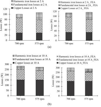
2.4.2 Simulation Results of Harmonic Iron Loss Determination at Various Operating Conditions ...31
2.5 Analytical Derivation of PWM Harmonic Factor Contributed by Magnet Eddy Current Losses ...32
2.6 Experimental Investigations ...35
2.7 Summary ...37
CHAPTER 3 INVESTIGATION INTO VARIATION OF PERMANENT MAGNET SYNCHRONOUS MOTOR AND DRIVE LOSSES FOR SYSTEM LEVEL EFFICIENCY IMPROVEMENT ...38
3.1 Introduction ...38
3.2 Mathematical Modeling of Inverter Losses ...41
3.2.1 Conduction Losses of VSI Inverter ...41
3.2.2 Switching Losses of VSI Inverter ...41
xiv
3.3.1 Copper Losses ...43
3.3.2 Fundamental Iron Losses ...43
3.3.3 Harmonic Iron Losses ...46
3.4 Dependence of Inverter Losses on Control Variables ...46
3.5 Dependence of Motor Losses on Control Variables ...49
3.5.1 Simulation Results of Fundamental Motor Losses with Varying Current Angle ...50
3.5.2 Simulation Results of Fundamental Motor Losses with Varying DC Link Voltage ...51
3.5.3 Results of Fundamental Motor Losses with Varying Switching Frequency ...53
3.5.4 Simulation Results of Harmonic Motor Losses with Varying DC Link Voltage ...53
3.5.5 Simulation Results of Harmonic Motor Losses with Varying Switching Frequency ...54
3.5.6 Simulation Results of Harmonic Motor Losses with Varying Current Angle ...55
3.6 Study of Magnet Eddy Current Losses with Varying Control Variables Using 2– D FEA Co-Simulation ...56
3.7 System Level Losses with Varying Control Variables ...57
xv
3.7.2 DC Link Voltage and Switching Frequency ...58
3.8 Experimental Validation in Laboratory Prototype ...60
3.8.1 Power Loss Sensitivity ...60
3.9 Discussion on Feasible Solutions for Improved PMSM System Efficiency ...62
3.10 Conclusions ...62
CHAPTER 4 STUDY OF PARAMETER VARIATIONS IN PM MACHINES CONSIDERING SATURATION AND TEMPERATURE VARIATIONS ...63
4.1 Introduction ...63
4.2 Off–line Parameter Identification based on Metaheuristic Optimization ...64
4.2.1 Improved LSIPMSM model Considering Saturation ...64
4.2.2 Employment of Optimization Algorithm and Parameter Identification ...68
4.2.3 Experimental Setup and Validations ...71
4.2.4 Results and Discussions ...73
4.2.5 Conclusions on Off–line Parameter Determination ...76
4.3 On–line Parameter Identification based on Multi–Parameter Estimation Considering Iron Losses ...77
4.3.1 Equivalent Circuit Modeling of PMSM Incorporating Iron Losses for On– line Identification of Parameters...77
xvi
4.3.3 On–line Multi–Parameter Determination through Two– Stage RLS
Estimation Algorithm ...80
4.3.4 Mathematical Modeling and Simulation of Proposed Algorithm for Parameter Identification ...84
4.3.5 Results and Investigation of Identified Parameters from Mathematical Model ...84
4.3.6 Impact of Iron Losses at Various Operating Points ...86
4.3.7 Experimental Validation of On–line Multi–Parameter Estimation and Results ...88
4.3.8 Conclusions on on–line parameter determination ...91
4.4 Conclusions ...92
CHAPTER 5 IMPROVED MAXIMUM EFFICIENCY CONTROL OF PERMANENT MAGNET SYNCHRONOUS MACHINES CONSIDERING EFFECTS OF CORE SATURATION AND TEMPERATURE VARIATION ...93
5.1 Introduction ...93
5.2 Development of Non–linear Model Based Efficiency Improvement Method ...94
5.2.1 Voltage Equation Based Flux Linkage Mapping Considering Saturation and Cross–Saturation ...95
5.2.2 Flux Linkage Considering PM Flux Variation Due to Temperature ...99
5.3 Implementation of Optimal Current Angle Computation ...101
5.3.1 Overview of Current Angle Derivation ...101
xvii
5.3.3 System Efficiency Computation for Optimal Current Angle Derivation ..106
5.4 Analytical Results from the Developed Method ...107
5.4.1 Results of Motor and System Efficiency Under Varying Operating Conditions ...107
5.5 Experimental Validation using Laboratory PMSM ...109
5.5.1 Experimental Setup ...111
5.5.2 Tests at Varying Load–Speed Points Using γMEPA ...111
5.5.3 Sweep tests for Optimal Current Angle Benchmarking ...112
5.5.4 Effects of Developed Method Considering Saturation ...114
5.5.5 Effects of Developed Method Considering Temperature Variation ...115
5.5.6 Comparison with Conventional MTPA Control ...116
5.6 Discussions and Conclusions ...117
CHAPTER 6 ON–LINE METHOD USING DC POWER MEASUREMENT FOR ENERGY EFFICIENCY IMPROVEMENT IN PMSM MOTOR DRIVE SYSTEM ....119
6.1 Introduction ...119
6.2 Loss Models for On–line System Efficiency Improvement ...120
6.2.1 Fundamental Losses in PMSM ...120
6.2.2 Harmonic Copper and Core Losses ...122
6.2.3 Inverter Losses ...124
xviii
6.3 Proposed Gradient Descent Algorithm Based Maximum Efficiency Optimization
Method ...125
6.3.1 Search for Maximum Efficiency Angle Using Gradient Descent Algorithm...125
6.3.2 Implementation of Developed Method in Test Motor ...128
6.4 Experimental Investigations and Validations of the Proposed Maximum Efficiency Control Method ...131
6.4.1 Implementation of Developed Method in Test Motor ...132
6.4.2 Sweep Tests for Optimal Current Angle Benchmarking ...133
6.4.3 Experimental Results on Efficiency Improvement in IPMSM ...134
6.5 Discussions on Adaptations of Developed Maximum Efficiency Control Method ...141
6.5.1 Dynamic Response and Improved Adaptations ...141
6.5.2 Look–up Table Generation ...141
6.6 Conclusions ...141
CHAPTER 7 CONCLUSIONS AND FUTURE WORK ...143
7.1 Conclusions ...143
7.2 Future Work ...145
BIBLIOGRAPHY ...146
APPENDICES ...155
xix
A.1 Bessel Function used in Derivations...155
Appendix B: Mechanical Loss Determination ...155
Appendix C: Dynamic Equations for PMSM Modeling ...156
Appendix D: Permissions for Using Publication ...158
xx
LIST OF TABLES
Table 2.1 Machine Design Parameters Used for Analytical Calculations ...16
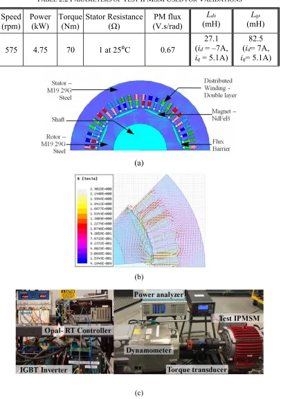
Table 2.2 Parameters of Test IPMSM Used for Validations ...16
Table 2.3 Magnet Losses for Various Carrier Frequencies with 200 VDC and 40 Hz Fundamental ...34
Table 3.1 Parameters and Values of IGBT Inverter used for Analysis ...42
Table 4.1 LSIPMSM Name Plate Data ...72
Table 4.2 Results of Identified Parameters of LSIPMSM ...73
Table 4.3 Comparative Results of Identified Parameters for Model 1 and Model 2 ...74
Table 4.4 Comparison of Simulated Inductance Estimation Results at Im=15.55 A, γ= 30.5 Deg and 600 rpm ...84
Table 4.5 Comparison of Experimental Inductance Estimation Results at Im=10 A, γ= 20 Deg and 200 rpm and 600 rpm ...89
Table 5.1 Flux Linkage Coefficients at 25 ⁰C ...98
Table 5.2 Values of Current Angles Obtained from Sweep tests ...113
Table 6.1 Parameters and values of IGBT Inverter Used for Analysis ...124
Table 6.2 Comparison of Actual and Calculated MEA at 700 rpm, Varying Im ...135
xxi
LIST OF FIGURES
Figure 1.1. A block diagram of Toyota Prius E–Motor and Drive. ...1
Figure 1.2. Efficiency maps for 2014 Honda Accord HEV at 300 V DC voltage. (a) Motor Efficiency. (b) Inverter Efficiency. (c) System Efficiency. ...4
Figure 2.1. Three–phase IPMSM designed and prototyped in–house with 48 slots, 8 poles distributed winding, and NdFeB35 magnets in the rotor. (a) Cross–section of the IPMSM. (b) Flux density distribution at rated condition. (c) Experimental setup with the laboratory prototyped motor. ...17
Figure 2.2. No–load back–EMF experimental validation of accuracy of 2–D electromagnetic analysis model used for validating developed model at 1,000 rpm. ...18
Figure 2.3. Stator and rotor of the prototype IPMSM under test. ...18
Figure 2.4. Magnitudes of frequency components in input voltage for frequency modulation=50. ...20
Figure 2.5. Representation of the rotor and reference axes in the IPMSM analyzed. ...21
Figure 2.6. Staircase function representing rotor MMF due to PM for one flux barrier per pole. ...24
Figure 2.7. Magnetic circuit network showing one pole pair used for calculation of rotor MMF. ...25
Figure 2.8. Results of the analytical model at 575 rpm, 10 kHz carrier frequency, 70 Nm and 200 V DC link voltage. (a) Stator MMF in rotor reference frame. (b) Rotor MMF considering fundamental and higher order carrier harmonics in input current. ...29
Figure 2.9. Comparison of air– gap flux density calculated with respect to rotor position using only fundamental component of armature reaction field in air–gap flux density analytical model with 2–D FEA for considering only fundamental current component. ..29
Figure 2.10. Comparison of air–gap flux density calculated with respect to rotor position using analytical model with 2–D FEA for considering space harmonics and side–band time harmonics in current. ...30
Figure 2.11. Comparison of air– gap flux density calculated with respect to time using analytical model with 2–D FEA for considering space harmonics and side–band time harmonics in current. ...30
xxii
Figure 2.13. Current harmonic magnitudes used to study magnet eddy current losses. ....34
Figure 2.14. Comparison of analytical and experimental results for total iron losses in stator under varying loading conditions for 200 rpm, 15 Nm and 7 kHz. ...35
Figure 2.15. Blocked rotor test for validation of developed model. (a) Test circuit representing input demagnetizing current. (b) Harmonic loss results including iron losses and magnet eddy current losses. ...37
Figure 3.1. Schematic depiction of controllable losses in PMSM drive system...38
Figure 3.2 Control scheme showing the variables for analyzing the behavior of system– level losses. ...40
Figure 3.3. d–and q–axis equivalent circuit model of IPMSM incorporating iron loss resistance. (a) d–axis model with iron loss. (b) q–axis model with iron loss. ...44
Figure 3.4. Iron loss resistance values for varying speeds from conducted on the laboratory IPMSM. ...45
Figure 3.5. Conduction losses as a function of varying inverter parameters. (a) Conduction losses varying with respect to Mi and load current. (b) Conduction losses as a function of
power factor angle and load current. ...47
Figure 3.6. Switching losses as a function of varying inverter parameters. (a) Switching losses varying with respect to fc and VDC. (b) Switching losses varying with respect to fc
and load current. ...47
Figure 3.7. Phasor diagram of IPMSM in motoring mode. ...48
Figure 3.8. Fundamental iron losses as a function of γ and varying Im at switching frequency
of 12 kHz and DC link voltage of 650 V. (a) Iron losses at 175 rpm. (b) Iron losses at 575 rpm. ...50
Figure 3.9. Fundamental copper and copper plus iron losses as a function of γ and varying
Im at switching frequency of 12 kHz and DC link voltage of 650 V. (a) Copper losses at
175 rpm. (b) Total fundamental losses at 575 rpm. ...51
Figure 3.10. Fundamental copper and iron losses as a function of DC link voltage at 575 rpm and 1000 rpm. (a) Constant torque region at 575 rpm and 70 Nm. (b) Flux –weakening region at 1,000 rpm and 40 Nm. ...52
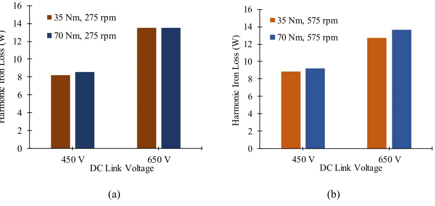
Figure 3.11. Comparison of harmonic iron losses at 450 V and 650 V and torques of 35 Nm and 70 Nm for varying speeds. (a) 275 rpm. (b) 575 rpm. ...54
xxiii
Figure 3.13. Comparison of harmonic iron losses for varying current angles at varying speed and load conditions. (a) Im= 2 A and varying speeds. (b) Im= 14 A and varying speeds.
...55
Figure 3.14. Comparison of magnet eddy current losses for varying switching frequencies and DC link voltage. (a) Varying switching frequency at 650 V. (b) Varying DC link voltage at 12 kHz. ...56
Figure 3.15. System losses calculated for varying current angles at 575 rpm and varying
Im. ...57
Figure 3.16. Input power, output power, losses and system efficiency calculated for varying current angles at 575 rpm and Im= 2 A. (a) Input and output power and total losses. (b)
System efficiency. ...58
Figure 3.17. System level power variation at rated speed and torque. (a) Losses as a function of fc at 650 V. (b) Losses as a function of VDC at 12 kHz. ...59
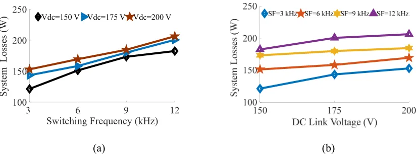
Figure 3.18. System power loss variation as a function of VDC and carrier frequencies. (a) Power loss variation as a function of VDC for fixed switching frequencies. (b) Power loss variation as a function of fc for fixed VDC. ...61
Figure 3.19. Input power, output power, losses and system efficiency calculated for varying current angles at 575 rpm and Im= 15 A. (a) Input and output power and total losses. (b)
System efficiency. ...61
Figure 4.1. Equivalent circuit illustration of conventional LSIPMSM dynamic model. (a) Direct axis. (b) Quadrature axis. ...65
Figure 4.2. Experimental results for d– and q–axis DC current test (a) d–axis inductance as function of time. (b) q–axis inductance as a function of time. ...68
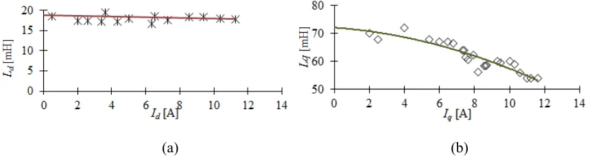
Figure 4.3. Experimental results for d– and q–axis magnetization characteristics. (a) d–axis inductance as function of d–axis current. (b) q–axis inductance as function of q–axis current. ...68
Figure. 4.4. Flow chart of the IPSO algorithm developed for parameter determination. ..69
Figure 4.5. Particles updating in a circular behavior ...69
Figure 4.6. Block diagram of experimental setup and optimization process. ...72
Figure 4.7 Experimental setup of the laboratory LSIPMSM. ...72
xxiv
Figure 4.9. Model validation for 60 Hz, 240V supply. (a) Measured phase currents Ia, Ib
and Ic. (b) Calculated phase currents Ia, Ib and Ic using identified model without saturation
(conventional) (c) Calculated phase currents Ia, Ib and Ic using identified model with
improved model accounting for saturation (developed model). ...75
Figure 4.10. Calculated results for identified model for 60Hz, 240 V supply. (a) Torque and speed characteristics. (b) Calculated phase current Ia. Model 1: Conventional model
without saturation, Model 2: Improved model incorporating saturation ...76
Figure 4.11. d− and q−axis equivalent circuit model of IPMSM incorporating iron loss resistance. (a) d–axis model with iron loss. (b) q–axis model with iron loss. ...78
Fig. 4.12. Iron loss resistance values for varying speeds from method 2 tests conducted on test IPMSM. ...79
Figure. 4.13. Structure of proposed two–step RLS estimation for multi–parameter estimation incorporating iron losses ...83
Figure 4.14. d–axis inductance vs current estimation with and without iron losses through mathematical model for IPMSM and comparison with 2–D FEA. ...85
Figure 4.15. q–axis inductance vs current estimation with and without iron losses through mathematical model for IPMSM and comparison with 2–D FEA. ...85
Figure 4.16. Relative error from actual value in estimation of d– and q–axis inductances with and without iron losses using mathematical model. ...86
Figure 4.17. d–axis inductance vs current estimation from mathematical model for IPMSM with and without iron losses and comparison with actual value. ...87
Figure 4.18. q–axis inductance vs current estimation from mathematical model for IPMSM with and without iron losses and comparison with actual value. ...87
Figure 4.19. Relative error of Lds from mathematically obtained values of d–axis inductance
with and without iron losses at varying load torque conditions. ...87
Figure 4.20. Relative error of Lqs from mathematically obtained values of q–axis inductance
with and without iron losses at varying load torque conditions. ...88
Figure 4.21 Three–phase currents obtained from experimental identification process for Im
=10 A and γ= 20˚ at a speed of 600 rpm. ...89
Figure 4.22. Measured Ids and Iqs currents for identification process at Im =10 A and γ= 20˚
at a speed of 600 rpm. ...89
Figure 4.23. Comparison of Lds and Lqs obtained experimentally from stage 1 of
xxv
Figure 4.24. Comparison of λPM obtained from stage 2 of identification at 600 rpm with
and without iron losses for Im =10 A and γ= 20˚. ...91
Figure 4.25. Measurement of winding temperature using thermocouples attached in the windings at Im=10 A and γ= 20˚ at a speed of 600 rpm. ...91
Figure 5.1. Flux linkage representation with respect to inductances and PM flux linkage depicting saturation and temperature variations effects. ...94
Figure 5.2. Block diagram representing test method for determination of flux maps experimentally. ...96
Figure 5.3. Procedure and measurements of current control used for flux linkage fitting 96
Figure 5.4. Flux linkage maps obtained in the d– and q– axis for room temperature. (a) d– axis flux linkage. (b) q–axis flux linkage. ...98
Figure 5.5. Permanent magnet temperature measured using thermal image camera at various operating conditions. (a) Room temperature. (b) Magnet temperature measured at 47ºC. (b) Magnet temperature measured at 60ºC...100
Figure 5.6. Permanent magnet flux variation with temperature. ...100
Figure 5.7. Stator temperature measurement and resistance variation with temperature (a) Stator temperature measurement using RTDs. (b) Stator resistance variation with temperature. ...101
Figure 5.8. Procedure of deriving optimal current angle for a specific speed and peak current at room temperature, T1. ...102
Figure 5.9. d− and q−axis equivalent circuit model of IPMSM incorporating iron loss resistance with respect to flux linkage. (a) d–axis model with iron loss. (b) q–axis model with iron loss. ...104
Figure 5.10. Simulated values of current angle, γMEPA with respect to peak current and
speed. ...108
Figure 5.11. Simulated values of efficiency variation with current angle showing maximum efficiency angles for varying speeds and Im = 2 A. (a) System efficiency. (b) Motor
efficiency. ...108
Figure 5.12. System efficiency corresponding to simulated values of current angle, γMEPA
in 3–D and 2–D forms. (a) Surface map of system efficiency. (b) System efficiency with respect to Im for various speeds. ...109
Figure 5.13. Motor efficiency corresponding to simulated values of current angle, γMEPA,m
xxvi
Figure 5.14. Control diagram for implementation of the developed maximum efficiency method in laboratory IPMSM drive. ...110
Figure 5.15. Comparison of experimental efficiency and simulated efficiency for various
Im and speeds at room temperature. ...112
Figure 5.16. Results from sweep test at 500 rpm and Im=10 A. (a) Efficiency vs current
angle. (b) Output torque vs current angle. ...113
Figure 5.17. Comparison of γMEPA,actual, γMEPA and γMEPA,unsat for varying Im at 575 rpm. 114
Figure 5.18. Efficiencies at 25⁰C and 85⁰C with temperature compensation with respect to γ and Im. (a) 25⁰C. (b) 85⁰C. ...115
Figure 5.19. Efficiencies obtained experimentally at 85⁰C with and without temperature compensation as functions of speed at 14 A and 2 A. ...116
Figure. 5.20. Efficiency comparison the developed method with MTPA for varying loading and speeds. ...117
Figure. 5.21. Motor efficiency comparison of the developed method with MTPA for varying loads and speeds. ...117
Figure 6.1. Iron losses calculated from no–load tests at varying speeds and flux linkages to determine average hysteresis and eddy current loss coefficients. ...122
Figure 6.2. Flowchart representing implementation of gradient descent optimization for maximizing efficiency in PMSM drives considering system losses. ...130
Figure 6.3. Implementation of the developed maximum efficiency angle detection. ...131
Figure 6.4. Results from sweep test at 700 rpm and Im=10 A. (a) Efficiency vs current angle.
(b) Output torque vs current angle. (c) DC voltage measurement. (d) DC current measurement. ...134
Figure 6.5. Current angle iteration to determine maximum efficiency angle at 575 rpm and current change from 6 A to 10 A; initial γ was γMTPA of 24.9 degree. ...135
Figure 6.6. Results of developed method to determine MEA during speed change from 575 rpm to 700 rpm at 6 A. (a) d−and q−axis currents, DC current and DC voltage (secondary axis). (b) d−and q−axis voltages. (c) Current angle iteration. ...136
Figure 6.7. Comparison of current angles at MTPA and MEA conditions for varying speeds and currents at 25⁰C operating temperature. (a) Current angles at 575 rpm and varying Im.
xxvii
Figure 6.8. Comparison of efficiency at MTPA and maximum efficiency current angle conditions for varying speeds and Im of 6 A and 10 A. (a) Efficiency at 575 rpm and varying Im. (b) Efficiency at 700 rpm and varying Im. ...137
Figure 6.9. Comparison of system efficiency at MTPA and maximum efficiency current angle conditions for varying speeds and load currents. (a) System efficiency at maximum efficiency angle. (b) System efficiency at MTPA angle. ...138
Figure 6.11. Three–phase PWM voltage measured at the motor terminals at 700 rpm for Im
=10 A and γ=36.5⁰ and corresponding spectrum. (a) Phase voltage measurement of PWM waveform. (b) Harmonic spectrum of PWM voltage. ...140
xxviii
NOMENCLATURE
A list of primary symbols is given here; there are more symbols used in this thesis, which
have been defined locally.
Te Electromagnetic torque id, iq d– and q–axis current vd, vq d– and q–axis voltage
λd, λq d–axis flux linkage
imd, imqd– and q–axis magnetizing currents Ri Iron loss resistance
λPM Permanent magnet flux linkage
Ld, Lq d– and q–axis inductances
ωs Electrical angular speed
ωc Carrier angular speed
Im Peak current
φ0 Initial voltage vector phase
θ Electrical rotor position
δ Torque angle
P Number of machine poles
J Combined moment of inertia
Rs Stator resistance
R0 Stator resistance at room temperature, T1 α Copper thermal resistive coefficient
xxix
fs, fc Fundamental frequency, Carrier/ switching frequency Fs, Fr Stator, Rotor MMF
Fsh HarmonicStator MMF
φs Initial phase of winding current
φh Initial phase of hth winding current harmonic
αp Pole arc coefficient
Bhg Harmonic airgap flux density
ϑs Angular coordinate in the stator
ϑr Angular coordinate in the rotor
μr PM relative permeability
Hc PM coercive force
hm Length of PM
g Length of airgap
tb, lb, Thickness, length of the flux barrier
ϑb Angle of the flux barrier
kt, ky Teeth width and yoke height coefficients
γactual Current angle for actual maximum system efficiency
γactual,m Current angle for actual maximum motor efficiency
At, Ay Teeth and yoke areas wt, wy Teeth and yoke widths
τs, τp Tooth and pole pitch
xxx
LIST OF ABBREVIATIONS
A list of key abbreviations is given here; there are more abbreviations used in this thesis,
which have been defined locally.
EV Electric vehicle
FEA Finite element analysis
FOC Field oriented control
IPMSM Interior permanent magnet synchronous motor
IGBT Insulated-gate bipolar transistor
IPSO Improved particle swarm optimization
LSIPMSM Line start interior permanent magnet synchronous motor
MCM Magnetic circuit modeling
MTPA Maximum torque per ampere
MMF Magnetomotive force
MEA Maximum efficiency angle
MEPA Maximum efficiency per ampere
PM Permanent magnet
PWM Pulse‒width modulation
RLS Recursive least square
RTD Resistance temperature detectors
1 CHAPTER 1
INTRODUCTION
1.1Overview of Electric Motors and Drives in Traction Applications
Electric machines and drives used in electric vehicles (EVs) have been receiving increasing
research and development interest in recent years due to environmental concerns and
emphasis on global energy savings. Advancements in the areas of electric motor and drive
design and control strategies have been in demand owing to the stringent requirements for
performance and efficiency in automotive systems, more–electric aircraft and ships. Using
new materials, innovative topologies and control strategies, it is possible to improve the
efficiency of the electric machine and the power electronic components existing in the
electric vehicle [1] – [5]. Figure 1.1 shows the block diagram of a commercial e–motor
drive system used in Toyota Prius [2].
Figure 1.1. A block diagram of Toyota Prius E–Motor and Drive.
Any energy savings in the electric motor and the power electronic converter of the EV
helps, which operates as an inverter during motoring operation, in obtaining longer
distances per charge in the EV owing to lower energy consumption from the battery [3]–
2
dissertation considers system– level efficiency improvement as the aim to extend the
driving range and reduce the overall operational costs of the electrified vehicle.
The converter losses are composed of semiconductor conduction losses and switching
losses, and are dependent on the converter topology, switching device characteristics and
switching frequency of the devices [2]. Apart from these loss components, the power
electronic converter also induces additional losses in the electrical machine as it produces
a switched output voltage waveform with increased harmonic content. This leads to
increased losses, additional heating and reduced lifetime of the machine. The electric motor
component produces the highest electric losses in a motor and drive system consisting of
the motor and the inverter [1]. The percentage of losses depends on the type of motor used.
Proper selection of electric machine type is based on key features such as the energy source
in the vehicle, space and vehicle dynamics, efficiency, reliability, cost, and the major
operating requirements of the machine. The major operating requirements of the traction
motor include a wide speed range, impulsive response, high efficiency over a wide torque
and speed, high torque at low speeds, fault tolerance, and high–power density.
Among the major automakers, there is no general consensus as to the type of electric
machine best suited for vehicles, but induction machines (IM) and permanent magnet
synchronous machines (PMSM) are the two types currently used in EVs and are expected
to continue to dominate the market [1], [2]. The PMSM machines have higher efficiency,
torque density, and heat dissipation capability than their IM counterparts and are widely
used in today’s EVs because of their superior performance over the induction machines.
Out of the various configurations in PMSM such as the surface PMSM (SPMSM), interior
3
continue to be the preferred choice compared to the other types [2]– [6]. Some of the
commercial EVs/ Hybrid EVs using IPMSMs include Chevy Volt, Mitsubishi i–MiEV,
Honda Accord, Nissan Leaf, Toyota Camry, Ford Focus, Toyota Prius, Lexus, etc. [2]. The
motor losses in an IPMSM include mechanical losses, copper losses in the windings, iron/
core losses in stator laminations, and magnet losses.
The efficiency map of the power components, that is the efficiency of the motor and
inverter as a function of torque and speed, which determines the energy losses and
consumption for vehicles, and the peak power characteristics, are important factors for
high–performance demands [2]. Figure 1.2 shows efficiency maps of electric motor,
inverter and system levels in 2014 Honda Accord [1]. It can be seen that the motor peak
efficiency is close to 95%, inverter is 99% and the system efficiency, which is the combined
efficiencies of the motor and inverter is 93%. It is to be noted that the component
efficiencies as well as the system–level efficiencies are lower than 90% in certain operating
conditions. The motor efficiency is also lower than 92% in high–speed, low–torque regions
as well as the low–speed, high–torque regions. These operating points are frequent in an
urban drive cycle and in some cases, highway driving cycle as well. Hence, it is important
to consider design or control techniques that can improve the efficiency of the system over
frequent operating points in a drive–cycle rather than achieving maximum efficiency at
certain operating points for significant improvements in battery energy consumption.
Many control algorithms aimed towards the reduction of the electrical loss components
during part load operation and increase in drive–cycle efficiency have been developed and
reported in the literature. In the next section, current research areas and factors influencing
4
(a)
(b)
(c)
5
1.2Review of Factors Influencing System Level Efficiency and Performance
Improvements in PM Based Electric Motor and Drive System
This research focuses on system level efficiency and performance improvements in PM
based electric motor and drives. There is significant research on inverter topology and
switch selection, pulse–width modulation type selection, etc. to improve the inverter
efficiency that also affects the motor performance [5]. However, the scope of this
dissertation is limited to improving the system level efficiency through improved motor
modeling, control and testing techniques only.
In the study of PMSM motor drive efficiency improvement, it is important to consider the
interaction of motor and drive and the behavior of one component with respect to the other.
The major factors influencing control algorithms for improved efficiency in traction PM
motor and drive can be summarized into the following:
1) Motor–drive interaction and accuracy of loss models
2) Parameter variations under varying operating conditions
3) Control algorithm and methodology of implementation
1.2.1 Motor–Drive Interaction and Accuracy of Loss Models
The electromagnetic field in the motor includes harmonics such as slot harmonics and
carrier harmonics. They cause considerable losses in the stator and rotor. In case of stator
laminations and rare earth magnets, the carrier harmonics produced by the pulse–width
modulated (PWM) inverter may cause increase in stator core losses as well as magnet
harmonic eddy–current losses, depending on the conductivity of the material and the
impedance of the harmonic circuit. The mathematical analysis of losses in inverter–fed
6
density significantly and hence increase the losses and degrade performance [7]– [9]. The
effect of PWM on losses and noise in electric motors have been widely studied in the
literature [8]– [11]. It has been studied previously that eddy current losses are affected
predominantly by PWM, especially in low–speed, low–torque regions of IPMSM [7], [9].
The main contribution factor is the time harmonics in both low frequency order as well as
high frequency carrier order [9]. Another loss factor is space harmonics in the form of
stator and rotor slotting [10]. The PWM based eddy current losses occur in stator and
magnet [9]. Some of the applications and methodology considering PWM input in stator
loss models include induction motors [11], finite element analysis (FEA) of IPMSM [9],
[10] and extension of research conducted on steel specimens energized with PWM supply
[11]. Regarding analytical techniques, winding function and semi-analytical method
combined with simplified FEA have been developed to consider space harmonics and
subsequently, effective motor design solutions have been proposed [14], but not including
PWM carrier harmonics. Thus, there is a need of accurate analytical harmonic iron loss
modeling in the stator core to study the influence of PWM harmonics on the motor and
develop control methodologies to reduce these harmonics for wide operating regions.
1.2.2 Parameter Variations Under Varying Operating Conditions
The efficient performance of variable speed motor drives depends on the controller
settings, which in turn depend on the accurate knowledge of the machine parameters that
establish the correlation between the input excitation and the resulting torque [3]. The
precise knowledge of machine parameters is beneficial not only for accurate control, but
also for obtaining the best performance from the motor at various operating points and for
7
operating conditions and temperature. Many techniques have been developed in the
literature to identify varying parameters of IPMSMs as well as SPMSMs. The methods for
identification performed experimentally can be classified as offsite experimental methods
[15], on–site and off–line methods [16], [17] and on–line techniques [18]– [21]. Off–site
experimental methods are either simple and include standard tests such as no–load, blocked
rotor tests, etc. or require special experimental setup and are widely used for parameter
determination in many types of electrical machines. However, the major drawback is the
poor representation of real operating conditions and non–linearities associated with the
machine. On–site and off–line test methods commonly make use of measurements from
experiments performed on the motor connected to the drive in various operating conditions
prior to actual operation and a search algorithm or a constrained optimization algorithm is
used to identify the parameters off–line. In such methods, the estimation and updating of
machine parameter information is not possible while it is in continuous operation, except
from 2– D or 3–D look–up tables that are cumbersome if all conditions need to be
incorporated. On–line parameter estimation methods are very popular and are used in
sensor–less and adaptive control of PMSM. Various algorithms have been used to identify
on–line, the inductances, stator resistance and PM flux linkage of the machine. Majority of
identification problems are focused on identifying one or two parameters by keeping the
other parameter as a constant. For instance, [19] identified inductances and winding
resistance by keeping the PM flux linkage constant. Multi–parameter estimation is the
estimation of all or many parameters simultaneously and some examples from literature
include [20]– [22]. In [20], a recursive least square (RLS) method was used to
8
dependence on off–line measurement for any of the parameters. In [21], additional
measurements such as power and torque were used for the on–line multi–parameter
identification problem. In [22], the problem of rank deficiency in identifying all parameters
was performed by d–axis current injection and solving two sets of simplified PMSM equations by using Adaline neural network theory.
The stator resistance and PM flux predominantly depend on temperature. The stator
winding temperature is dependent on operating conditions including load, operating
frequency, cooling conditions, etc. On the other hand, the magnetic parameters, d– and q– axis inductances largely depend on the operating flux level of the machine. Most of the on–
line multi–parameter identification techniques provided in the literature review neglect the
impact of iron losses on the estimation process. Majority of estimation including iron losses
in literature have been performed in induction motors [23] and a few in PMSMs [24]– [27].
The impact of iron losses has been observed to be significant in the estimation of stator
resistance, magnitude changes in the back EMF and output torque calculations [25]. In
sensor–less control, there is significant angle estimation error in case of models neglecting
iron loss factor [26]. In PMSM, most of the work performed including iron loss is either
off–line or neglects the simultaneous estimation of other parameters [25]– [28]. The iron
loss factor is generally ignored in low speed operations, even in case of high torque
conditions. However, the effect of iron loss could be significant in high torque conditions
[18]. Hence, is important to study the parameter variations accurately and also consider the
iron loss factor at high torque conditions, especially in EV application where torque/
9
1.2.3 Control Algorithm and Methodology of Implementation
Of the various control methods, development of optimal control strategies to maximize
efficiency have been of significant interest in the literature [32]– [48]. Recent research
topics in control of PMSM to improve efficiency include improved maximum torque per
ampere (MTPA) to reduce copper losses [32]– [39] and loss minimization (LM) through
model based or search controller–based techniques [42]– [49]. The main difference
between MTPA and other loss minimization strategies is that the former can only minimize
copper losses whereas the latter can reduce the iron losses as well. In general, the necessary
features to be addressed in developing control methods for efficiency improvement can be
summarized as: (1) Applicability of the developed method in real conditions when
parameter variations in motor is inevitable; (2) Scope of power loss reduction at component
and system level; and (3) Ease and methodology of control implementation.
In PMSM control, MTPA is one of the most widely used techniques where the objective is
to obtain an optimal current angle that consumes minimum stator current for a required
output torque. In terms of applicability in real conditions, MTPA angle derivation has been
performed using parameter–based approaches [32]– [34] and on–line techniques such as
signal injection and DC power measurement which are robust against parameter variations
[35]– [38]. In model–based derivations, inductance variations due to magnetic saturation
and stator resistance and permanent magnet (PM) flux variation due to temperature are
vital factors to be addressed. In [32], MTPA angle was calculated using look–up tables of
parameters for varying operating condition. However, it is tough to include parameter
variations considering saturation, cross–saturation and temperature simultaneously through
10
calculate the MTPA angle in real time. However, these methods can suffer from rank
deficiency issues. Some of the solutions suggested use extra invasive measurements or
methods such as torque sensor or temperature sensors [37] or current and voltage signal
injection [36], [38] that could increase machine losses. In [39], DC power measurement
was considered to compute optimal voltage. However, the method depends on motor model
and is not entirely robust against parameter variations. In general, even though robustness
against parameter variations can be considered, MTPA method does not provide a true
optimal efficiency point as only copper losses are minimized. The motor iron and harmonic
losses are ignored, even though they are significant at higher speeds [40], [41].
In loss minimization techniques towards better efficiency considering iron losses, the main
difference from MTPA is the improvement in scope of optimal current distribution
derivation in d– and q–axis by considering iron loss, stray loss, etc. Typically, loss minimization in PMSM can be classified into model based [42]– [44], search based [47],
[48] and hybrid methodologies [49]. The model–based methods derive LM using motor
model where the d– and q–axis currents are derived by solving constrained optimization problem using numerical methods or approximate analytical solutions [42]– [45]. The
optimal values can be generated as look–up tables to be used in the control [42] or solved
on–line [44]. The search–based methods aim to drive the control variable towards
minimum power loss, regardless of the motor ratings or parameters [46]– [48]. However,
search methods are slower than model–based techniques and are sensitive to current and
voltage harmonics and cause torque ripple due to perturbations. Hybrid loss minimization
methods were developed to comprehend the advantages of both model– and search–based
11
system through control variables have been studied [50]– [52], a loss minimization method
for PMSM that is robust and improves the scope of loss reduction by considering losses
from a system level is not yet fully developed.
1.3Motivation of the Thesis
Given the drawbacks in the methods developed in literature regarding the three major
factors affecting control algorithms towards motor and drive efficiency improvement, this
thesis contributes to novel modeling, testing and control methodologies aimed towards the
energy efficiency improvement of a PMSM motor- and drive system. The approaches are:
(1) Accurate analytical modeling and testing of loss components in PMSM considering
inverter harmonics; (2) Easy–to–implement, accurate parameter determination techniques
to understand variations in motor parameters due to saturation, cross– saturation and
temperature; and, (3) Control methodologies to improve system level efficiency
considering improved loss models and parameter variations.
The overall objectives are summarized as follows:
1. Understand the sources of losses in PM machines through comprehensive study
using analytical models, numerical simulations and experimental tests.
2. Derive improved analytical model for air–gap flux density considering various
sources of harmonics such as time and space caused by PWM–fed inverter and
motor design parameters for improved loss models.
3. Identify control parameters affecting various losses in an insulated-gate bipolar
transistor (IGBT) –fed PMSM and perform a study to understand loss behavior with
respect to varying control parameter and propose the chosen control variable
12
4. Develop methods of identifying varying parameters in IPMSM such as inductances
due to saturation and PM flux due to temperature and understand their effects on
system efficiency.
5. Validate developed loss models and parameter determination methods in laboratory
PMSM through simulations and experimental investigations for various operating
conditions.
6. Propose efficiency improvement method considering the improved loss models and
variation of parameters under wide speed and torque regions.
7. Explore efficiency improvement from a system–level with parameter
independence.
8. Analyze improvements in efficiency considering the developed methodologies in
laboratory PMSM using numerical and analytical simulations and experiments.
1.4Dissertation Outline and Research Contributions towards Improved System
Efficiency in PMSM Drives
This dissertation proposes novel modeling, testing and control methodologies towards
global improvement of efficiency in permanent magnet synchronous motor drives from a
system level. This dissertation presents 5 chapters excluding this introductory chapter and
the conclusion chapter that present the research conducted and novel research contributions
made while working towards the overall objectives. The chapter outlines, and major
contributions of this work are highlighted as follows:
Chapter 2 proposes the eddy current loss behavior due to time and space harmonics through a novel analytical modeling. An improved winding function theory incorporating armature
13
analyze the air–gap flux density including harmonics. Further study on stator and rotor
eddy current losses has been performed. It was concluded that the PWM harmonics cause
significant increase in losses and it is imperative to consider the dependency and
controllability of the harmonic losses and methods of reduction through control techniques,
especially in stator harmonic losses.
Chapter 3 proposes a detailed investigation into behavior of controllable losses in PMSM as functions of control variables such as current angle, DC link voltage, and switching
frequency. The loss model proposed in Chapter 2, in addition to inverter loss models and
fundamental loss models of the motor, have been used in a field– oriented control (FOC)
based simulation to study the system level losses. The analysis suggested that the change
in current angle can affect the overall system losses and that for every operating point there
exists an optimal distribution of current that lead to maximum system efficiency.
Chapter 3 concludes that the optimal current value selection helps in improving efficiency of the system. However, it is vital to understand parameter variations with loading and
speed in order to model the motor and drive efficiency close to actual conditions and further
study system efficiency. Chapter 4 proposes methods of testing equivalent circuit parameters through off–line and on–line methods to study parameter variation due to
saturation and temperature variations. Easy to implement off–line parameter determination
using improved particle swarm optimization (IPSO) and on–line multi–parameter
estimation through recursive least square (RLS) method have been developed. The
methods suggested significant changes in motor parameters in the laboratory test motors.
The developed on–line method was also used to study the influence of iron loss on output
14
Given the understanding of system efficiency behavior in a PMSM drive, an off–line loss
minimization procedure was developed in Chapter 5 using a search–based approach towards minimization of system losses. The effects of parameter variation due to saturation
and temperature have been considered using flux linkage maps to avoid the segregation of
saturation and temperature effects in d–axis flux linkage. The losses in the motor were calculated considering these parameter variations. Improved optimization procedure to
calculate optimal d– and q– axis currents considering the flux linkage–based loss models enables considering the effects of saturation, cross–saturation and temperature variation in
stator and rotor. The inverter losses were included in deriving the optimal current angle.
The comparison with conventional MTPA is provided along with experimental validations
in laboratory test motor.
Chapter 6 proposes an on–line loss minimization procedure to improve the system efficiency considering DC power measurement and helps to simplify the consideration of
parameter variations in real–time conditions. Firstly, the motor and inverter loss models
were derived in such a way that the calculation can be performed using terminal
measurements in a PMSM drive. Consequently, a gradient descent search–based algorithm
is used to calculate the optimal current angle corresponding to maximum system efficiency
from the input DC power measurement and output power based on the loss models. The
developed method was compared against conventional MTPA and validated
experimentally.
Chapter 7 summarizes the developed methods and their contributions towards the PMSM system efficiency improvement as well as proposes some future work to be considered as
15
The test motor used for all analysis in this thesis is a 4.25 kW laboratory IPMSM except
the off–line parameter estimation technique wherein a line–start IPMSM (LSPMSM) has
been used. However, the knowledge from the tests have been used for the IPMSM study.
All contributions, including loss models, parameter determination, control algorithms and
corresponding experimental validations have been proposed keeping the IPMSM as a test
case. It is to be noted that many of the contributions of this dissertation, especially the
control algorithm improvements, can be easily applied to SPMSMs by modifying the
equivalent circuit parameters accordingly and is expected to provide improved energy
16 CHAPTER 2
COMPREHENSIVE ANALYTICAL MODELS TOWARDS STUDY OF HARMONIC
MOTOR LOSS BEHAVIOUR IN A PWM–FED PERMANENT MAGNET MACHINE
2.1Introduction
In this chapter, loss models are developed to study the behaviour of losses with respect to
operating conditions. The behaviour of fundamental and harmonic losses in a PWM–fed
IPMSM are studied. The time harmonics from inverter are significant in IPMSM and can
cause increase in stator core eddy current losses. This chapter aims at modeling the
harmonic losses accurately in an IPMSM, and subsequently study methods of reduction
through control techniques. The outcomes of the loss modeling and analysis are used in
Chapter 3 to study the behaviour of motor losses to varying control variables that can
optimize the system efficiency. The proposed loss models include time harmonics from the
PWM inverter and space harmonics from the motor design to analyze the fundamental and
harmonic losses in the stator and rotor of the motor.
To study the behaviour of the aforementioned losses, a 4.25 kW laboratory IPMSM is used
for investigations. The design parameters of the motor are given in Table 2.1.
TABLE 2.1MACHINE DESIGN PARAMETERS USED FOR ANALYTICAL CALCULATIONS
Description Value
Stator outer, inner diameter 220.137 mm, 134.137 mm Rotor outer, inner diameter 133.137, 85 mm
Number of poles (p) 8
Slot number, conductor per slot 48, 28
Pole arc/ pole pitch 0.82
Tooth width, slot pitch 4.96 mm, 8.78 mm
Magnet width, thickness 36 mm, 6 mm
Magnet electrical conductivity 62500 S/m
17
TABLE 2.2PARAMETERS OF TEST IPMSMUSED FOR VALIDATIONS
Speed
(rpm) Power (kW) Torque (Nm) Stator Resistance(Ω) (V.s/rad) PM flux
Lds
(mH) L
qs
(mH)
575 4.75 70 1 at 25⁰C 0.67
27.1 (id = –7A, iq = 5.1A)
82.5 (id= 7A, iq= 5.1A)
(a)
(b)
(c)