20th International Conference on Structural Mechanics in Reactor Technology (SMiRT 20) Espoo, Finland, August 9-14, 2009 SMiRT 20-Division 5, Paper 2564
1
Response of graphite dowel-socket structure under various loads
Han Fengshan, Sun Libin
Institute of Nuclear and New Energy Technology, Tsinghua University, Room 310, Energy Source Building B, Beijing, 100084, P. R. China, e-mail: [email protected], [email protected]
Keywords: HTR, graphite components, dowel-socket, equivalent stiffness.
1
ABSTRACT
Graphite components are the main part of core structures of high temperature gas-cooled reactor (HTR). Unlike metallic components which can be welded or riveted together, those graphite components should only be connected by dowel-socket and key-keyway structures to transfer horizontal forces and to restrict correspondingly horizontal motion to ensure the integrity of the whole core structure.
Among the assembly of graphite components, small clearance remains to accommodate thermal and fast neutron irradiation strains. Under dynamic loads, such as seismic excitations, impact would occur among graphite components due to the clearances. Therefore, in addition to investigating the response of graphite socket structure under various loads, it’s necessary to study the influence of different gaps of dowel-socket structure on the load-deformation response of the graphite structure. Since the final goal is to investigate the integrity of the whole core structure, it is necessary and important to obtain the equivalent stiffness of dowel-socket structure consisting of two graphite blocks, which is considered as the basic component of the whole core structure.
In this paper, by finite element code ANSYS, the load-deformation response (equivalent stiffness) of the graphite dowel-socket structure is studied, and the influence of different gaps of dowel-socket structure on the response is discussed.
2
INTRODUCTION
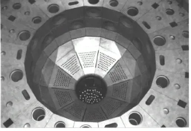
The high temperature reactor developed in China is pebble-bed high temperature reactor (HTR), of which the internals are different to that of block-type fuel high temperature reactors. The 10MW High Temperature gas-cooled Reactor (HTR-10, one test HTR built in China) is shown in figure 1 and figure 2, and the graphite components of the internals are shown in figure 3 (Zhensheng Zhang, 2002).
One of the most important aspects in developing HTR is to ensure the integrity of the core and safety shutdown of the reactor in case of operational as well as accident conditions. It is necessary to know how the core behaves under dynamic loads, especially in an earthquake. However, discovering the behaviour is difficult, because thousands of graphite bricks are employed in the HTR core and each brick has an independent kinematic capability under dynamic loads such as seismic excitation. These graphite bricks, which can not be welded or riveted together like metallic components, are connected by dowel-socket or key-keyway structures. To accommodate thermal and fast neutron irradiation expansions, clearance is remained between dowel and socket as well as key and keyway.
The connecting systems of both dowel-socket and key-keyway structure are crucial elements for assessing the integrity of the components, not only because the vibrational characteristics of the assembly of graphite components are dominated by the connecting systems, but also because the dynamic load caused by such as earthquakes concentrates on these components (Iyoku et al., 1994). Hence from the viewpoint of the aseismic integrity of the graphite components it is very important to investigate the behaviour of the dowel-socket structure.
2
feasible and unnecessary for analytical method to treat all the graphite components of the internals as elastic or plastic material to assess the integrity of the whole core. It is reasonable to idealize the graphite bricks as rigid bodies, while the connecting structures as systems of spring in parallel with dashpot (Ikushima, Nakazawa, 1979; Ahmed, 1987). Therefore, to obtain the equivalent stiffness of dowel-socket system is essential to well evaluate the integrity of the internals analytically. The stiffness of the spring is investigated analytically and experimentally considering quasi-static and dynamic states (Futakawa et al., 1994).
Figure 1. Core structures in HTR-10
Figure 2. Lower structure of side and bottom reflectors
Figure 3. Graphite and carbon bricks in side reflector and insulation
The paper analytically studied the response under diverse direction loads of basic structure of the internals, i.e. two bricks connected by two dowels vertically, which is implemented through finite element
1. Fuel feed tube 2. Dish-shape spring 3. Control rod 4. Ceramic internals 5. Core barrel 6. Reactor pressure vessel 7. Reactor core 8. Fuel discharge tube 9. Singularizer 10. Fuel removal tube 11. Support bearing 12. Hot gas duct 13. Experimental channel
14. Channel for small absorber balls 15. Guide key
1. Graphite sleeve for control rod guide channel 2. Rectangular key 3. Dowel
3
method (FEM) code ANSYS, from aspects of static and transient analysis. Because the stiffness and the stress distribution of the dowel-socket structure seem to be strongly affected by the contact behaviour between the dowel and socket, the analysis mainly focused on the simulation of the contact behaviour (Futakawa et al., 1996). The analytical results are used to guide the process of and verified by the experiment.
3
STATIC ANALYSIS
3.1 Analytical model
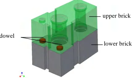
In this section, the behaviour of the basic component of the internals (i.e., dowel-socket structure) under static load from three different directions was investigated. The structure of two bricks vertically connected by dowels is shown in figure 4. The bricks are almost hexahedrons, of which the dimension is 750×472×300mm. For the convenience of analysis and experiment, the structure could be reduced to as shown in figure 5 a), of which the dimension is 500×200×300mm, with two sockets placed symmetrically with distance of 280mm. The dimension of the socket is"80!30mm; while that of the dowel is
mm 8 5 5 . 79 and mm 8 5 7 . 79 , mm 8 5 9 .
79 ! " ! " !
" respectively (which corresponds to clearance of dowel-socket of 0.1mm, 0.3mm and 0.5mm) to study the influence of different gaps on the behaviour of the structure. The load directions are illustrated in figure 6.
Figure 4. Schematic diagram of dowel-socket structure
a) whole model simulating on load F2 and F3 b) half model simulating on load F1
Figure 5. Analytical model of dowel-socket structure
The material of the model is nuclear graphite IG-11, just as that used in the HTR-10 internals. The main mechanical properties are shown in table 1.
Table 1. Main mechanical properties of graphite IG-11
4
(GPa) ratio (t/m3) (MPa) strength (MPa)
8.3 0.14 1.77 25.3 76.8
Figure 6. Schematic diagram of load directions 3.2 Contact pairs and meshing
The processing of the contact pairs is the most important in the analysis. There are seven contact pairs for the whole model, i.e., two of dowel side to socket side, two of dowel bottom to socket bottom of lower brick, two of dowel top to socket bottom of upper brick and one of upper brick bottom to lower brick top face. Correspondingly, the half model has four contact pairs. The dowel is meshed with Solid186, which is a higher order 3-D 20-node solid element, while the bricks with Solid187 which is a higher order 3-D 10-node element. Those elements have three degrees of freedom per node: translations in the nodal x, y, and z directions. In the model, Conta174 and Targe169 are employed to simulate the surface-surface contact of the contact pairs. The meshed model is schematically shown in figure 7, and the amounts of elements and nodes produced in the model are listed in table 2.
a) mesh of the model
b) mesh of dowel
c) mesh of graphite brick
Figure 7. Mesh of the analytical model
5
(displacement in z direction) of the top surface of upper brick is constrained to 0. There are also symmetrical constraints in the half model, of course. Load F1 and F2 are applied on the surface A and B respectively in manner of displacement, while F3 is applied on the surface A and B synchronously.
Table 2. The element and node produced in the model
half model whole model total
dowel upper
brick
lower
brick dowel
upper brick
lower brick
half model
whole model element
type Solid186 Solid187 Solid186 Solid187 - -
element 2100 6372 8135 2115 12082 13806 16607 30118
node 9556 10914 13684 9572 20288 22921 34154 62353
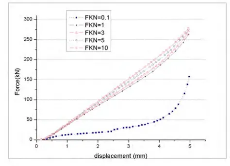
Since the penalty algorithm is employed in the model, it is important to designate the real constant FKN which defines normal contact stiffness factor. The value of FKN affects the penetration of contact surface and the stiffness of the structure: the smaller value requires larger penetration while underestimate the stiffness of structure; the larger value could reduce the penetration and estimate the stiffness of structure more accurately, while would lead to convergence problems. The relationship of reaction force and displacement as a function of the value of FKN is shown in figure 8 which is obtained by half model under F1 load, where the force is the reaction force of the dowel while the displacement is the mean displacement of the bottom vertexes of upper brick.
From figure 8, it can be deduced that the relationship of the force and displacement is pretty stable and shows a good agreement when FKN=1, 3, 5 and 10. However, with the increasing of the value of FKN, the analysis becomes more involved and needs more time. Therefore, it is advisable to define FKN=1.
Figure 8. The relationship of reaction force and displacement
3.3 Analytical results
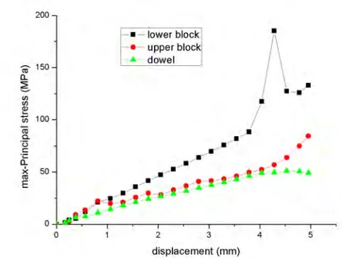
Graphite is kind of brittle material to which the maximum principal stress theory is usually applied. The relationship of maximum principal stress and displacement of different part of the structure is shown in figure 9. As shown in figure 9, the maximal stress of the structure takes place at the lower brick; therefore, the fracture of the lower brick is the most concern of failure of the structure.
6
Figure 11 and figure 12 respectively show the influence of gap of dowel-socket and load direction on the relationship of reaction force and displacement. From figure 11 and figure 12, it can be seen that the structure shows nonlinear characteristic when the displacement is less than 0.5mm whatever the gap is and load direction is, followed by a linear relationship of force and displacement. This is because the contact area enlarges with the increasing of displacement when it is not large enough. Figure 12 shows a nonlinear diversity versus different load directions when the displacement reaches about 3mm. This is supposed related to the swirling of dowel and distance difference of socket to the edge of the brick along the load direction. However, the structure is assumed to failure when the effective displacement reaches about 3mm. therefore, the equivalent spring of the connecting system of dowel-socket structure could be reduced as a bilinear spring.
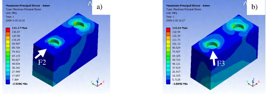
Figure 13 shows the difference of the distribution of maximum principal stress of the lower brick under load direction F2 and F3. The distribution of stress around the socket is almost the same against their load direction.
Figure 9. Relationship of maximum principal stress and displacement of different part of the structure
Figure 10. Distribution of the maximum principal stress a) around the socket of the lower brick b) of dowel
7
Figure 11. The influence of gap of dowel-socket on the relationship of reaction force and displacement
Figure 12. The influence of load direction on the relationship of reaction force and displacement
Figure 13.
Difference of the distribution of maximum stress of the lower brick
4
TRANSIENT ANALASYS
In the transient analysis, take the half model with gap of 0.5mm which bears F1 load as an example to study.
In the assembly of the core, the mechanical response characteristics of graphite components may be affected magnificently by damping or gravity. Figure 14 shows the influence of whether the gravity is taken into account in the FEM analysis on the equivalent stiffness of structure. From the figure, the trends of the relationship of reaction force and displacement are rarely affected by whether the gravity is taken into
F2
F3
8
account or not. However, the reaction force shifts to larger displacement, about 0.3mm. This might be caused by the larger penetration tolerance allowed by ANSYS without gravity concerned. The larger displacement can be eliminated in the post processing. So, to save much calculating costs, the analysis can consider no influence of gravity temporarily.
Figure 14. The influence of gravity concerned or not on the structural equivalent stiffness
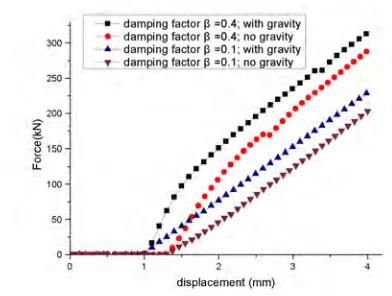
The material damping factor can be estimated by collision test. The eqn(1) was given to calculate the damping factor h of graphite material under circumstance of the coefficient of restitution was obtained by test, which was about 0.4~0.7 (Ikushima et al., 1982). According to eqn(1), therefore, the material damping factor of graphite IG-11 is about h=0.1128~0.2800. The structure response is investigated while the material damping factor is 0.1, 0.2 and 0.4.
!
!
"
#
$
$
%
&
'
'
=
2 1 2
)
1
(
exp
h
h
e
(
(1)where: e, coefficient of restitution, (-);
h, damping factor, (-).
Figure 15 shows the influence of material damping factor on the relationship of reaction force and displacement. It can be seen that with the increasing of damping factor, the structure tends to stiffer and more energy is dissipated during loading and unloading. Therefore, it can be concluded that the damping factor can affect the dynamic behaviour of the structure magnificently.
9
5
CONCLUSION
To investigate the structural integrity of the HTR core, the response of graphite dowel-socket structure was studied analytically, whose results will supply guidance for and be verified by experiments that are underway. From the analysis, the following conclusions can be obtained.
(1) The gap of dowel-socket struture rarely affects the equivalent stiffness of the structure. Therefore, as to the gap of dowel-socket structure, the investigation should focus on its influence of impact under dynamic loads and the influnce of the accumulation of gaps on the structural deformation limits.
(2) The responses of the structure are almost the same under different load directions before the failure of the structure.
(3) The fracture would first take place around the socket of lower brick at about ±75°-85° from the load direction, while the rupture of dowel would not show up in the structural failure.
(4) The structure has a nonlinear characteristic due to the contact behaviour of the dowel-socket. And the equivalent stiffness of the structure can be reduced to a bilinear equivalent spring.
(5) In the transient analysis of the structure, the effect of gravity can be ignored, of which the influence is neglectable. The material damping factor has a noticable effect on the dynamic behaviour of the struture. With the increasing of the damping, the structure tends to be more stiffer. Much more investigation should be done on the influence of damping factor on the structural response.
Acknowledgements.
The study is financially supported by National S&T Major Special Project (No. 2008zx06901-005), which the authors would like to gratefully acknowledge.
REFERENCES
K. M. Ahmed. 1987. The dynamic research of multi-layers AGR core brick arrays. Nuclear Engineering and Design. Vol. 104. P. 1-66.
M. Futakawa, T. Iyoku, H. Shirai, S. Takada and M. Ishihara. 1994. Evaluation of Aseismic integrity in HTTR core-bottom structure II. Vibrational characteristics of keyed graphite components. Nuclear Engineering and Design. Vol. 148. P. 83-90.
M. Futakawa, S. Takada, H. Takeishi and T. Iyoku. 1996. Evaluation of aseismic integrity in the HTTR core-bottom structure V. On the static and dynamic behavior of graphitic HTTR key-keyway structures. Nuclear Engineering and Design. Vol. 166. P. 47-54.
T. Ikushima, T. Nakazawa. 1979. A Seismic Analysis Method for a Block Column Gas-Colled Reactor Core. Nuclear Engineering and Design. Vol. 55. P. 331-342.
T. Ikushima, T. Honma, H. Ishizuka. 1982. Seismic Research on Block-Type HTGR Core. Nuclear Engineering and Design. Vol. 71. P. 195-215.
T. Iyoku, M. Futakawa and M. Ishihara. 1994. Evaluation of aseismic integrity in HTTR core-bottom sturcture I. Aseismic test for core-bottom structure. Nuclear Engineering and Design. Vol. 148. P. 71-81.