ISSN(Online) :2319-8753
ISSN (Print) : 2347-6710
I
nternational
J
ournal of
I
nnovative
R
esearch in
S
cience,
E
ngineering and
T
echnology
(An ISO 3297: 2007 Certified Organization)
Vol. 4, Issue 9, September 2015
Pulse Wheel/ Flywheel; the Hidden Science,
for Developing Technologies
Saurabh Vikas Chaudhari.
B.E. Student, Dept. of Mechanical Engineering, J.T.M.C.O. Engineering, Faizpur, Maharashtra, India
ABSTRACT: In the I.C. engines there are four strokes suction-compression-expansion-exhaust. During the expansion
stroke due to fuel blast in the cylinder, thrust is produce and piston moves downward. The reciprocating motion of piston in downward direction pushes the crank between certain degrees in every 360 degree rotation. This indirectly adds a power pulse in the flywheel attached to the engine shaft. Similarly but using electric motor with friction tooth power pulse can added to flywheel directly with more numbers of power pulses. This creates power and torque equivalent to I.C Engine which can utilize for various purposes. This pulse wheel/ flywheel mechanism (without piston) helps to gain the benefit of multi cylinder engine and saves fuel.
KEYWORDS: Pulse wheel/ flywheel, I.C engine, power pulse, Friction tooth, mechanism (i.e. pulse mechanism).
I. INTRODUCTION
I.C engine has so many uses; mostly it is used for power generation that means to run the gen set and to run automobiles. As the demand of electricity is increasing day by day in many areas of developing countries there is lack of power supply hence peoples have to suffer from load scheduling of 5 to 6 hours and for the peoples in rural areas every night is black night. Hence in so many areas of developing countries now peoples are using generator sets operated by petrol or diesel for power back up.
The main problem with these fossil fuels is that their availability is very less and will get exhaust soon as the load is increasing on them due to increasing automobile industry and diesel gen sets. The exhaust gases escaping from the I.C engine are harmful for the environment and increasing the contribution in environmental problems like Global warming.
The pulse wheel is the mechanized wheel having same capacity of power generating like I.C engine but using electric motor. I.C engine needs to increase the numbers of cylinders to increase the number of power pulses in one 360 degree rotation to maintain the compression pressure and torque but, the pulse flywheel has feature that number of power pulses can be added to the single flywheel/ wheel using single electric motor in one 360 degree rotation which maintains the torque as well as power. Due to pulse wheel/ flywheel there is no need of fossil fuel for power generation hence the pulse wheel/flywheel is the best option for I.C engine generators.
II. BACKGROUND
In I.C engine there are four main processes compression-expansion-exhaust. But during the process of suction-compression and exhaust process there is no any power input in the flywheel keyed on the engine shaft. During the process of expansion that means when the blast of the injected fuel takes place the pushing thrust is produce on the piston head and piston moves in downward direction. The thrust helps in energy addition in the flywheel which applies on a flywheel through crank for the short period and this generates high power rotational motion, which used for automobile and electricity generation purpose. The main drawback is that it needs fossil fuel as a burning fuel which will exhaust soon and pollutes the environment.
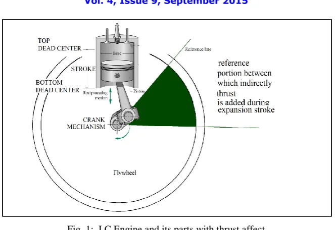
Fig. 1: I.C Engine and its parts with thrust affect
Above figure illustrates the reference portion showing effect of impulsive thrust on the flywheel which indirectly applies on it during the expansion stroke. The effect of impulsive thrust is not on the certain portion of flywheel, it acts on the whole area of flywheel but it applies through certain degrees of flywheel till the piston reaches to BDC from TDC.
In October 2009, Lawrence Tseung and his band of helpers demonstrate the pulse theory of energy addition based on gravity. Theory explains that “if an energy pulse is applied to a flywheel, then during the instant of that pulse, excess energy equal to 2mgr is fed into the flywheel, where “m” is the mass (weight) of the flywheel, “g” is the gravitational constant and “r” is the radius of the centre of mass of the flywheel”.
This means that if the flywheel is driven smoothly at constant speed, then there is no energy gain. However, if the drive is not smooth, then excess energy is drawn from the gravitational field. That energy increases as the diameter of the flywheel increases. It also increases as the weight of the flywheel increases. It also increases if the flywheel weight is concentrated as far out towards the rim of the flywheel as is possible. It also increases, the faster the impulses are applied to the system.
III. SCOPE OF RESEARCH
The scope of the pulse wheel/ flywheel is mainly in the I.C Engine electricity generators to eliminate (if electric motor is used) or to minimize the amount of burning fuel in I.C Engine assembly. Also it is useful in automobiles, ships, airplanes for power generation purpose etc.
ISSN(Online) :2319-8753
ISSN (Print) : 2347-6710
I
nternational
J
ournal of
I
nnovative
R
esearch in
S
cience,
E
ngineering and
T
echnology
(An ISO 3297: 2007 Certified Organization)
Vol. 4, Issue 9, September 2015
IV. METHODOLOGY
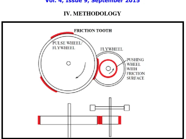
Fig. 2: arrangement of friction tooth and pushing wheel.
The pulse flywheel is designed such that due to number of friction tooth fixed on its circumference generates energy equivalent to the I.C Engine. As illustrate in FIG. 2; there are two shafts in mechanism (pulse mechanism), pulse flywheel is mounted on the first shaft and pushing wheel with the small flywheel is keyed on a second shaft where the friction surface is regular on the pushing wheel. More than one friction tooth can be fixed on the circumference of the pulse wheel/ flywheel, since energy is transferred from pushing wheel to the pulse wheel/ flywheel impulsively by applying power pulses. The power pulse to the pulse wheel/ flywheel is apllied through dirct contact using pushing wheel. The pushing wheel is rotated by using electric motor which consumes low power as compared to outut of the alternator. The energy generated due to rotational motion is stored into the flywheel mounted on second shaft with pushing wheel which helps to transfer the high energy pulses.
Fig.3: Difference between pulse wheel and pulse flywheel.
Similarly, pulse wheel can be use as a pushing wheel but, the flywheel or simple wheel mounted on first shaft must have continuous friction surface on its contacting surface.
Fig.4: basic construction for the use of pulse wheel
The Fig.4 illustrates the basic construction of the mechanism to use the pulse wheel, it is not the rigid structure it is flexible and the one may change the construction. As shown, to transfer the power as an input to the mechanism, small capacity I.C Engines (a)/ gas turbine and steam turbine (b)/ electric motor (c) can be use.
ISSN(Online) :2319-8753
ISSN (Print) : 2347-6710
I
nternational
J
ournal of
I
nnovative
R
esearch in
S
cience,
E
ngineering and
T
echnology
(An ISO 3297: 2007 Certified Organization)
Vol. 4, Issue 9, September 2015
Due to use of the pulse wheel/flywheel the energy required to generate the rotational motion is very less, because in the pulse wheel/flywheel the energy is added through circumferential area which makes the flywheel easy to rotate. It should be noted that the length of the friction tooth on the circumferential surface of the pulse wheel/flywheel should be in length equal to the distance between the BDC and TDC of the I.C Engine cylinder of which equivalent energy is to be generate using pulse wheel/flywheel. The ratios between the pushing wheel and the pulse wheel/flywheel (radial
ratio) should be 1:3/1:4/1:5 i.e. if the alternator is of the 1500 rpm and directly coupled to the first shaft of the
mechanism then the rpm of pushing wheel should be 4500 rpm (radial ratio1:3 is considered). Similarly, for alternator having 300 rpm or more these ratios are suitable. The maximum the radial ratio lower the input energy required for the mechanism.
Let:
R= outermost Radius of the pulse wheel/flywheel with thickness of friction tooth. r = outermost radius of pushing wheel with the thickness of friction surface. N= speed of the first shaft (rpm)
n = speed of the pushing wheel (rpm)
Then,
Using above relation (pulse mechanism equation i.e. PME), we can easily find out the exact figures required for the construction of the mechanism. If the numbers of the pulse wheel or the flywheel mounted on the first shaft is increased then, care should be taken that each pulse wheel/flywheel must have separate pushing wheel.
To maintain the continuous contact between the friction tooth and the pushing wheel compression spring or tension springs should be provide to pushing wheel mechanism. Which will helps to maintain the frictional grip between the two meeting friction surfaces with better pressure such that slip losses will minimize. To store the maximum energy in the second shaft required to apply the high energy power pulse on the friction tooth small flywheel must be provided on second shaft but, the flywheels should be rimmed disk flywheel which will generate maximum moment of inertia due to rotational motion. Due to simple functioning and construction of the pulse wheel/flywheel the pushing wheel can be place at anywhere around the circumference of the pulse wheel/flywheel, it will not affect the performance of the mechanism but, the care must be taken that the pushing wheel and pulse wheel/flywheel get in contact perfectly with best frictional grip.
As there is circumferential contact between the pushing wheel and pulse wheel/flywheel in the mechanism, the speed of the first shaft is maintained by maintaining the speed of the electric motor which drive the second shat of the mechanism. The use of dimmers or rheostats or voltage regulators is suitable for maintaining the speed of an electric motor. Due to friction between the two meeting frictional surfaces heat is produce in the mechanism so in purpose to maintain the working temperature appropriate cooling system should be provide for continuous working.
V. EXPERIMENTAL RESULTS
For 1 MW generator:-
Generator Size (kW) 1/4 Load (gal/hr) 1/2 Load (gal/hr) 3/4 Load (gal/hr) Full Load (gal/hr)
500 11.0 18.5 26.4 35.7 600 13.2 22.0 31.5 42.8 750 16.3 27.4 39.3 53.4 1000 21.6 36.4 52.1 71.1 1500 32.2 54.3 77.8 106.5 2000 42.8 72.2 103.5 141.9 [02] STEAM TURBINE-
Now, to get the value of coal in kg/day consumed by the steam turbine for 1 MW power gen.:- P= 1 MW = 10000000 watt = 1000000 joule/sec = 239 kcal/sec
Since [P= Q/T]
Thermal power plants has 35% overall efficiency due to losses in various cycles Hence, Actual Q = 239/0.35 = 683 kcal/sec.
Now assume that plant is using Indian coal of grade D having calorific value 4200 kcal/kg. Hence amount of coal = 683/4200 = 162 grams/ sec.
For a load of 1MW for 1 day = 0.162 * 24 * 3600 = 14000 kg /day i.e. 14000/24 = 583.33 kg/hr.
As from the above results we can see that to generate 1MW of power diesel generator consumes 71.1 gallon/hr and steam turbine consumes 583.33 kg/hr which puts tremendous load on the fossil fuels and also pollutes the environment on high rate, but if we puts pulse wheel/flywheel to generate power in diesel generate then only single cylinder engine is capable to produce equivalent amount of the power and in steam turbine generator set small capacity steam turbine also used to generate same power which will lower the amount of burning fuel.
1) For diesel engine using pulse wheel/flywheel (if the generator is assumed as 4 cylinders) :- 71.1/4 = 17.77 gal/hr.
2) For steam turbine using pulse wheel/flywheel (assumed that steam turbine is of capacity of 1/3 rd power) :- 583.33/3 = 194.44 kg/hr.
From the above calculations, can assure that there is tremendous saving in burning fuels due to use of pulse wheel/flywheel in steam turbines and I.C Engine powered generators.
*Other results are:-
[01] Due to impulsive transformation of energy, flywheel gains and store more energy due gravitational energy acting on it.
[02] The number friction tooth provides power pulse through pushing wheel to the flywheel, which provides advantage of multi cylinder I.C Engine to the system which saves fossil fuel to some extent.
[03] As the number of friction tooth increases the output power of the generation system increases. There is no unbalancing in the mechanism so it can be use to run high speed alternators for generating power.
VI. POSSIBLE MODIFICATIONS
[01] More than one friction tooth can be fixed on flywheel or wheel in purpose to increase efficiency.
[02] More than one pulse wheel/pulse flywheel can mounted on first shaft. Care should be taken that number pushing wheels must equal to the number of pulse wheel / pulse flywheel.
[03] Reverse arrangement is possible; pulse wheel can be use as a pushing wheel while the flywheel or simple wheel mounted on first shaft must have the continuous friction surface on its contacting surface.
ISSN(Online) :2319-8753
ISSN (Print) : 2347-6710
I
nternational
J
ournal of
I
nnovative
R
esearch in
S
cience,
E
ngineering and
T
echnology
(An ISO 3297: 2007 Certified Organization)
Vol. 4, Issue 9, September 2015
VII. CONCLUSION
“When the energy is transferred from one mechanism to second mechanism impulsively through intermittent contact in purpose to maintain the continuous motion of energy receiving (second) mechanism to the design values, then this process of energy addition is to be called as Power Pulse/ Energy Pulse addition.”
Pulse wheel/ flywheel is a result of hidden or indirectly applied science behind I.C Engine mechanism (seems to me) and can be use for the power generation purpose with less input energy or fuel. Even mechanism is simple but, phenomena behind I.C Engine and pulse wheel/ flywheel is same. As the power transmission from input shaft to the output shaft is impulsive it also comes under the theory of Mr. Lawrence Tseung so there are high chances to get excess
output using pulse wheel/flywheel.
REFERENCES
[01] Patrick J. Kelly “Gravity-Powered Systems” From A Practical Guide to Free-Energy Devices [02] Domkundwar, ., “Internal Combustion Engines”, Dhanpat Rai & Co. New Delhi.
[03] Willard W Pulkrabek. “Internal Combustion Engines”, Pearson Education
[04] Shyam K. Agrawal, “Internal Combustion Engines”, New Edge International Publication. [05] K.K. Ramalingam, “Internal Combustion Engines”, Scitech Publication
[06] V. Ganeshan, “Internal Combustion Engines”,2/e, Tata McGraw Hill, New Delhi.
[07] E. F. Obert , “Internal Combustion Engines and Air Pollution”, Harper and Row, New York.
[08] Chas Champbel’s System.
[09] Chun-chao Wang, Yuh-suiang Wang “Gravity Power Generation Mechanism” United States patent number: 20090115195 A1 App No- 11/935,228 May, 2009.
BIOGRAPHY
Saurabh Vikas Chaudhari studying in last year of mechanical engineering in J.T. Mahajan
College of Engineering, Faizpur (Maharashtra). He is working on gravity based power generation systems and has applied (awaiting examination) for Patent. He researched and collaborate the gravitational theories of Sir Isaac Newton and Mr. Lawrence Tseung for power generation. He is the
first, who puts the pulse mechanism based on I.C Engine working phenomena (applied for patent).