ABSTRACT
FANG, XIAOMENG. Anisotropic D-EAP Electrodes and their Application in Spring Roll Actuators. (Under the direction of Dr. Tushar K. Ghosh).
Electroactive polymers (EAPs) exhibit shape change when subjected to an electric field. They are lightweight, soft, and inexpensive, while they are easy to process, shape, and tune to offer a broad range of mechanical and electrical properties. Dielectric electroactive polymers (D-EAP) constitute a class of EAPs with great potential. D-EAPs consist of physically or chemically cross-linked macromolecular networks and are mechanically isotopic. Therefore, in most actuator applications that require directional electromechanical response, it is necessary to use other complex means to direct the stress/strain in the preferred direction. In this work, a simple carbon nanotube (CNT) based electrode for D-EAP actuators is demonstrated that vastly improves directional strain response originating from the mechanical anisotropy of the electrode material. Using this novel approach, the mechanical anisotropy, defined as the ratio of initial modulus in fiber direction and that in cross-fiber direction, of the CNT electroded VHB actuators, ranges from 7.9 to 11.2. Hence, the CNT-VHB flat film actuators show high directed linear actuation strain in cross-fiber direction of greater than 25% meanwhile almost no strain in fiber direction at a relatively low electric field (120 V m-1).
Anisotropic D-EAP Electrodes and their Application in Spring Roll Actuators
by Xiaomeng Fang
A dissertation submitted to the Graduate Faculty of North Carolina State University
in partial fulfillment of the requirements for the degree of
Doctor of Philosophy
Fiber and Polymer Science
Raleigh, North Carolina 2017
APPROVED BY:
_______________________________ _______________________________
Dr. Tushar K. Ghosh Dr. Richard J. Spontak Committee Chair
DEDICATION
BIOGRAPHY
Xiaomeng Fang was born in China and she received her Bachelor’s degree in 2008 and Master’s degree in 2011 both in Textile Science and Engineering from Donghua University, China. During her master’s study, she worked on 3D orthogonal woven ramie fabrics reinforced polypropylene composites. She was awarded Major Award of Hongkong Sangma Trust Fund Scholarship, Chinese National Scholarship for Encouragement and Outstanding Academic Performance Scholarship of Donghua University in 2007, Outstanding Graduate student of Donghua University in 2009, Outstanding Graduate Student of Shanghai and Outstanding Individual of Social Practice of College Students of Shanghai in 2011.
ACKNOWLEDGMENTS
I would like to thank my advisor Dr. Tushar K. Ghosh for his guidance, support and motivation throughout my doctoral studies. He encouraged me to think and learn that has been very import for me to finish my study. Dr. Ghosh has always been patient and encouraging in times of problems and setbacks in my work. I also want to express my gratitude to Dr. Ghosh’s family for being an extremely caring host for me in this foreign county.
I am thankful to Dr. Philip D. Bradford for his supports with CNT synthesis. He also kindly allowed me to share the facilities in his lab with me to conduct my experiments. I am thankful to Dr. Richard J. Spontak. After leaning in his two courses in Polymer Science and Technology, Polymer Blends and Alloys, my understanding on fundamental polymers morphologies and properties was extensively broadened and improved. My thanks to Prof. Ericka Ford for agreeing serve in my committee.
I also want to say thanks to my graduated group mates Enes, Krishna, Aylin who lead me to start my journey in our lab and trained me in using the instruments. I would like to thank my current group mates Huiqi Shao, Elena Morgan, Kony Chatterjee and Ashish Kapoor for their kind support and caring.
I really want to express my gratitude to my family members. Their unconditional love and understanding always give me motivation and happiness. I would also like to thank my husband Dr. Kun Luan. He helps me when I have problems, takes care of our families when I am busy, shares his happiness with me and takes care of me.
TABLE OF CONTENTS
LIST OF TABLES ... ix
LIST OF FIGURES ... x
CHAPTER 1 Introduction ... 1
1.1 Introduction ... 1
CHAPTER 2 Electroactive Polymers ... 4
2.1 Introduction ... 4
2.1.1 Electric EAPs ... 6
2.1.1.1 Electromechanical Principles ... 7
2.1.1.2 Martials... 10
2.1.2 Ionic EAPs ... 17
2.1.2.1 Ionic Polymer Gels... 17
2.1.2.2 Ionomeric Polymer-Metal Composites ... 19
2.1.2.3 Conducting Polymers ... 21
2.1.2.4 Carbon Nanotubes ... 23
2.2 Dielectric Electroactive Polymers ... 26
2.2.1 Characteristic Parameters ... 27
2.2.1.1 Actuation Stress and Blocking Force ... 28
2.2.1.2 Blocking Force ... 29
2.2.1.3 Actuation Strain ... 30
2.2.1.4 Elastic Strain Energy Density ... 31
2.2.1.5 Electromechanical Coupling Efficiency ... 32
2.2.1.6 Electric Breakdown Strength ... 33
2.2.1.7 Effects of Prestrain on Actuation Performance ... 33
2.2.1.8 Instability and Failure ... 40
2.2.2 Materials and Properties ... 45
2.2.2.1 Silicone ... 46
2.2.2.4 Block Copolymers ... 52
2.2.3 Compliant Electrodes ... 58
2.2.3.1 Carbonaceous electrodes ... 60
2.2.3.2 Metallic electrodes ... 61
2.2.3.3 Conductive Polymer Electrode ... 64
2.2.3.4 Electrolyte Solution Electrode ... 65
2.2.3.5 Ionic Conductor Electrode ... 66
2.2.3.6 Self-healing Electrode... 67
2.2.4 Actuators Design and Applications ... 70
CHAPTER 3 Dielectric Electroactive Polymer Linear Actuators ... 73
3.1 Introduction ... 73
3.2 Linear Actuators ... 74
3.2.1 Extender Structure ... 74
3.2.2 Stretched Film Structure ... 75
3.2.3 Bowtie Structure ... 78
3.2.4 Diamond-shaped and Similar Structures ... 79
3.2.5 Stacked Structure... 81
3.2.6 Helical Structure ... 89
3.2.7 Folded Structure ... 92
3.2.8 Rolled Structure ... 95
3.2.8.1 Spring Roll Structure ... 95
3.2.8.2 Core Free Roll ... 102
3.2.9 Fiber-like Cylindrical Actuator ... 110
3.2.10 Cone Structure ... 112
CHAPTER 4 Carbon Nanotube Sheet Electrodes for Anisotropic Actuation of Dielectric Elastomers ... 117
4.1 Introduction ... 117
4.3.1 Sample Preparation ... 122
4.3.2 Actuator Characterization ... 122
4.4 Actuator Performance ... 123
4.4.1 Mechanical Behavior ... 123
4.4.2 Morphological Characteristics ... 125
4.4.3 Electrical Behavior of Electrodes ... 127
4.4.4 Electromechanical Properties ... 128
4.5 Conclusion ... 132
CHAPTER 5 Enhanced Anisotropic Response of Dielectric Elastomer Actuators with Microcombed and Etched Carbon Nanotube Sheet Electrodes ... 134
5.1 Introduction ... 134
5.2 Experimental... 140
5.2.1 CNT Synthesis and Preparation ... 140
5.2.2 Microcombing Process... 140
5.2.3 Actuator Preparation... 140
5.2.4 Laser Ablation Process ... 141
5.2.5 Actuator Characterization ... 141
5.3 Result and Discussion ... 142
5.3.1 Morphological Characteristics ... 142
5.3.2 Tensile Behavior ... 144
5.3.3 Electrical Behavior... 147
5.3.4 Field-induced Deformation ... 149
5.4 Conclusion ... 153
CHAPTER 6 Anisotropic D-EAP and Application in Spring Roll Actuator ... 154
6.1 Introduction ... 155
6.2 Materials and sample preparation ... 158
6.2.1 Spring ... 158
6.2.4 Spring roll actuator preparation ... 161
6.3 Characterizations of fiber/VHB composites flat film actuator and spring roll actuator ... 162
6.3.1 Mechanical tests of fiber/VHB composites ... 162
6.3.2 Blocking force tests of flat film actuator made of fiber/VHB composites 163 6.3.3 Field-induce deformation characterization of flat film actuator and spring roll actuator made of fiber/VHB composites ... 163
6.4 Result and discussion ... 164
6.4.1 Mechanical test results of fiber/VHB composites ... 164
6.4.2 Field-induced electromechanical response tests ... 167
6.4.3 Blocking force test results of flat film actuator made of fiber/VHB composites ... 169
6.5 Working principle of spring roll actuator ... 171
6.6 Fiber reinforced VHB composite spring roll actuator ... 173
6.6.1 Passive equilibrium statue ... 173
6.6.2 Initial moment of activation ... 181
6.6.3 Active equilibrium ... 182
6.7 CNT sheet electroded spring roll actuator ... 191
6.7.1 Spring roll actuator preparation and characterization ... 191
6.7.2 Result and discussion ... 191
6.7.2.1 Mechanical test results of CNT-VHB flat film actuator ... 191
6.7.2.2 Field-induced electromechanical response test results ... 194
6.7.2.3 Blocking force test results ... 195
6.7.2.4 Spring roll actuator performance characterization ... 196
6.8 Conclusions ... 198
CHAPTER 7 Conclusion and Future Perspective ... 201
REFERENCES ... 204
LIST OF TABLES
Table 2.1 Comparison of the properties of EAP, SMA and EAC [2]. ... 5
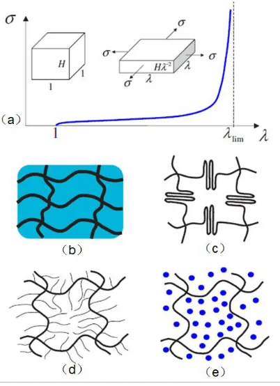
Table 2.2 Maximum response of representative elastomers [7] ... 56
Table 2.3 Summary of electrode options for dielectric elastomers [220] ... 68
Table 3.1 Comparison among various rolled D-EAPs in literatures(reference[309]) ... 106
Table 5.1 Comparison of mechanical, electrical and actuation anisotropy of actuator with aligned CNT sheet electrodes and actuators with fiber reinforcement. In all but one case (as noted) the D-EAP material is VHB-4905 acrylic. ... 152
Table 6.1 Spring specifications ... 158
Table 6.2 Specifications of monofilaments used to reinforce VHB composites ... 160
Table 6.3 Dimensions of the spring roll actuator ... 177
Table 6.4 Number of layers in spring roll actuators with constant length ... 180
LIST OF FIGURES
Figure 2.1 Classification of Electroactive Polymers [2] ... 6 Figure 2.2 Classification of dielectric materials [17] ... 7 Figure 2.3 Schematic illustration of crystal structures in 𝜷 phase of PVDF [24]. ... 11 Figure 2.4 Electrostrictive graft elastomer. (a) schematic illustration of molecular structure of electrostrictive graft elastomer; (b) bimorph actuator within inactivated (middle) and activated states (left and right) made from electrostrictive graft elastomer [42]. ... 14 Figure 2.5 Different geometries of the synthesis of LCEs. (a) side-chain elastomers and (b) main-chain elastomers [58]. ... 16 Figure 2.6 Schematic illustration of anisotropic phase of liquid crystal part transfers to the isotropic phase with increasing temperature and dimensional change [61]. ... 16 Figure 2.7 Deformation of polyelectrolyte gels under the influence of electric field [69], (a) schematic illustration of bending mechanism; (b) bending motion of the gel in the electric field. ... 18 Figure 2.8 Schematic illustration of the bending mechanism of a typical IPMC [78] ... 19 Figure 2.9 Molecular conformational changes of conductive polymers while redox reactions
Figure 2.13 Schematic illustration of circular strain set-up and photographs of acrylic elastomer under the circular strain testing. ... 31 Figure 2.14 Stress-strain curves of VHB elastomers with different strain and relaxation [122]
Figure 2.23 Ideal stress-strain curve and molecular structure of dielectrics with Type III failure type. (a) stress-strain curve of a membrane under biaxial stress; (b) fiber embedded in a compliant matric; (c) a network of polymers with folded domains; (d) a network of polymers
with side chains; (e) a network of polymers swollen with a solvent [150]. ... 44
Figure 2.24 The chemical structure of silicone elastomers... 46
Figure 2.25 The chemical structure of acrylic elastomers. ... 49
Figure 2.26 Young’s modulus as a function of temperature for the VHB 4910 and silicone hardened with 5% hardener [125] ... 49
Figure 2.27 Cyclic actuation of (a) silicone (b) acrylic elastomer VHB F-9437PC actuators [125]. ... 50
Figure 2.28 Schematic illustration of the morphology of a polyurethane elastomer where the hard segments (hatched boxes) are embedded in the matrix of soft segments (thin lines) [162] ... 51
Figure 2.29 Chemical structure of thermoplastic SEBS elastomer [214] ... 54
Figure 2.30 The equivalent circuit of film shaped dielectric elastomer actuator. ... 59
Figure 2.31 Zigzag patterned gold compliant electrodes. (a) zigzag gold electrodes undergoing large strains; (b) structured electrodes [219]. ... 62
Figure 2.32 Peak isotonic transverse strain vs. electric field for the different electrode materials and a pre-stress of (a) 19.6 kPa, (b) 29.4 kPa, (c) 39.2 kPa and (d) 49.0kPa. [222] ... 66
Figure 2.33 Comparison of high-speed actuators technologies Linear Actuators [247] ... 72
Figure 3.1 Dielectric elastomer actuator configurations [4,8] ... 74
Figure 3.2 Extender configuration for linear actuation [115] ... 75
ANTLA integrated with output shaft; (d) backbone shaped bending devices driven by ANTLA.
[253] ... 77 Figure 3.5 Bowtie configuration actuator. (a) Working mechanism of bowtie actuator; (b) silicone bowtie actuator; (c) multilayer double bowtie actuator with acrylic film [8]... 78 Figure 3.6 Bowtie D-EAPs actuator used in biomimetic applications [247]. (a) acrylic bowtie shaped actuator in self-contained six-legged robot “FlEX”; (b) flapping wing thorax-type design using D-EAPs ... 79 Figure 3.7 Diamond-shaped actuator. (a) schematic of four-bar mechanism based actuator with “negator” [258]; (b) schematic of a compliant symmetric double slider-crank mechanism with elastic joints on the slider pivot [259]; (c) assembly and prototype of acrylic diamond-shaped actuators [257] ... 80 Figure 3.8 Different designs for the flexible frame. (a) hexagon structured frame; (b) racetrack shaped frame; (c) prototype hexagonal structured actuator with and without actuation [260]; (d) stress relaxation of the nylon frame induced loss of blocking force as a function of time [258]. ... 81 Figure 3.9 Stack configuration. (a) schematic of D-EAPs stacked actuator before and after actuation [262]; (b) stacked actuator consists of alternating electrodes and elastomer [261] 82 Figure 3.10 Tactile display with stacked configuration. (a) the schematic drawing of the elastomer stack with patterned electrodes; (b) D-EAPs contracts at the actuated point with can inducing tactile sensation of finger; (c) passive matrix arrangement of the electrodes [262,263]
Figure 3.32 Progress diagram of automatic rolling up stage for assembling core-free D-EPAs roll actuators [312]. ... 110 Figure 3.33 Fiber-like cylindrical actuator. (a) schematic of the fiber actuator;(b) axial actuation (about 10%) strain produced in uniaxially prestretched silicone based prototype [313]. ... 111 Figure 3.34 Coextruded D-EAPs fiber actuators. (a) coextrusion mechanical schematic diagram; (b) coextruded fiber cross section; (c) an example of an assemble single fiber actuator; (d) an example of an assembled rope actuator with the ends capped with an epoxy plug. [315]
... 112 Figure 3.35 Working principle of cone shaped D-EAP linear actuator. (a) Prototype with and without electrically stimulation [318]; (b) schematic drawing of the working principle [319]. ... 113 Figure 3.36 Passive and active stiffness curves with various bias mechanism [316] ... 114 Figure 3.37 Biasing mechanisms in cone shaped actuators. (a) spring [316,319]; (b) weight
stress-strain diagram of the 25th cycle for 6 (●), 25 (▲), and 40% (■) strain amplitudes. The solid lines connect the data in all cases. ... 125 Figure 4.3 Optical images of electrodes showing morphological changes of CNT sheet electrodes, (a) sample under 10% tensile strain in the y-direction showing fracture, the inset shows bridging fibers across lines of fracture, (b) sample after 25 cycles of 25% strain along the y-direction. Optical and SEM images (as insets) of, (c) CNT fiber clusters of tightly folded undulations and kink bands (circled area) in strain-cycled sample as in (b), (d) sample after 25 strain cycles of 25% strain in the x-direction... 126 Figure 4.4 Electrical resistance of the CNT sheet electrodes measured along y (■) and x (●) directions, plotted as a function of applied strain in the, (a) y-direction, and (b) x-direction. The solid lines connect the data, and the error bars represent one standard deviation around the mean. ... 128 Figure 4.5 Linear actuation strain plotted, (a) as a function of nominal electric field in the fiber (○) and cross-fiber (●) directions together with directionally uniform response of a similar actuator with carbon-grease electrode (■), (b) as a function of actuation cycle number for actuators at 50 and 80 V m-1 electric fields as labeled. The inset of (a) shows the variation or tensile modulus of the VHB-CNT samples as a function of cycle number. The solid lines represent exponential fits to the data in (a) and the same in (b) is used to connect the data. Video capture images illustrate a test specimen, (c) before actuation, (d) at 80 V m-1, and (e) at 100 V m-1. ... 129
respectively. Insets (c) and (d) are SEM (surface) and TEM (cross-sectional) images of CNT electrodes, respectively, showing penetration of CNT fibers in the elastomer after 25 cycles of actuation. ... 132 Figure 5.1 Schematics illustration of (a) operational principle of D-EAP actuators, (b) microcombing (on the left) and laser ablation (on the right) processes. The laser ablation process is used to selectively remove CNT fibers along 360 m wide lines from the CNT sheet on the surface of VHB actuator, leaving stripes of 180 m width. ... 139
Figure 6.1 (a) Load-displacement curve of compression spring; (b) stress-strain curves of unidirectional tensile tests of monofilaments used to reinforce VHB composites. Inset is tensile young’s modulus results. ... 159 Figure 6.2 Schematic illustration of fiber reinforced VHB composites cross-section within 3mm length. ... 160 Figure 6.3 Preparation of spring roll actuator. (a) Schematic illustration and (b) photographs of fabrication process. ... 162 Figure 6.4 Unidirectional tensile test results of VHB and its composites. Stress-strain curves of strain alone (a) fiber direction (y) and (b) cross-fiber direction(x). (c) Initial modulus of composites straining in both fiber(y) and cross-fiber(x) directions. ... 165 Figure 6.5 Photographs of cutting off edge of composites located above the top clamp before tensile testing. (a) PA-I reinforced composites, (b) PA-II reinforced composites and (c) PU reinforced composites. ... 165 Figure 6.6 Stress supporting the prestrained VHB. It is recorded in tensile testing after mounting the sample, clamping samples and zeroing load cell, then the force was recorded after cutting off the film above the top clamp. ... 166 Figure 6.7 (a) Linear actuation strain as a function of true electric field of flat circular actuators. (b)-(e) is actuation video capture of VHB, PA-I/VHB composites, PA-II/VHB composites and PU/VHB composites actuator before actuation, respectively; (f)-(i) is capture of them at about 110 V/m. ... 168
Figure 6.11 Schematic illustration of process to preparing elastomer roll and the stresses in coordinates ... 173 Figure 6.12 Load-length curve of spring and inactive VHB roll ... 176 Figure 6.13 Photographs of (a) compressed spring and (b) spring roll actuator made of VHB elastomers. (c) Radial pressure (
elstr
) as a function of radius in the spring roll actuator (assuming each layer thickness t is 0.055mm withh
=0.468MPa and spring outside diameteri
r
is 8.63mm) ... 178CHAPTER 1 Introduction
1.1 Introduction
Actuators are used to convert a form of input energy into motion. Typical input energy may be one of electrical, thermal, magnetic, chemical, or compressed fluid (air/water/oil). Due to the diversity of forms of input energy, actuators are highly versatile. Traditional electromagnetic motors, pneumatic, and hydraulic actuators, are used extensively in many everyday applications. However, these traditional actuators are generally bulky, heavy, noisy, and rigid, therefore not particularly suitable for many of today’s applications such as microrobotics, mobile devices, and soft electronics that often require high power/torque to mass ratio, direct-drive, conformability, and small form factor.
Among the various EAP materials, dielectric electroactive polymers (D-EAP) offer many distinct advantages, including high energy density, remarkably high actuation strain, moderate stress, and tunability of properties [3–7]. In order to meet the actuation requirements of different applications, various configurations of actuators based on D-EAPs have been proposed. Among them, linear actuators are able to directly deliver a contractile/extensive stroke. This particular mode of actuation is required for a variety of application, such as simulation of human muscle motions [8–11]. Spring roll actuator, as one type of linear D-EAP actuators, consists of a compressed spring in the core and wound D-EAP roll as shell [12,13], is the focus of this work.
D-EAPs consist of physically or chemically cross-linked macromolecular networks [14] and are mechanically isotopic. Under an applied electric field, the in-plane expansions are uniform in every direction. However, in many actuator applications that require directional electromechanical response [15], it is necessary to use other complex means to direct the stress/strain in the preferred direction.
This dissertation is organized in most parts as research papers that have been or will be published with minimum changes.
Chapter 1. Introduces the contents covered and their organization in this dissertation
Chapter 2. Contains the review of fundamental electromechanical transduction principles and material categories of electroactive polymers (EAPs), with particular emphasis on the dielectric electroactive polymers (D-EAP).
Chapter 3. Reviews the linear D-EAPs actuators on the basis to their configurations, discusses their working principle, performance characteristics, processing techniques, and potential applications.
Chapter 4. Demonstrates the bifunctional carbon nanotube (CNT)-based electrode that serves both as an electronic conductor and a mechanically anisotropic constraint to produce directional actuation of the D-EAP.
Chapter 5. Explores the effects of improving alignment of CNT sheet through microcombing and selective laser ablation for application in D-EAP actuators to enhance anisotropic electromechanical response.
Chapter 6. Investigates different types anisotropic D-EAPs and their application in spring roll actuators. Analytically and experimentally examines ways to improve actuation performance of spring roll actuator.
CHAPTER 2 Electroactive Polymers
2.1 Introduction
Electroactive polymers (EAP) form a distinct class of polymers within the stimuli responsive polymers that undergo dimensional change upon the application of an electric field. Over the past few decades, EAPs have attracted tremendous attention of researchers from different disciplines because of their broad range of electromechanical properties, ease of processing and diverse potential applications in contemporary technologies. [2,16].
Table 2.1 Comparison of the properties of EAP, SMA and EAC [2].
EAP SMA EAC
Actuation strain (%) > 10 (up to 380 a) < 8 short fatigue time 0.1-0.3 Generated stress
(MPa)
0.03-43a about 700 30-40
Response speed 𝜇sec to min sec to min 𝜇sec to
sec
Density (g m-3) 1-2.5 5-6 6-8
Stimulation electric potential/filed
2-7 V (Ionic EAP)
10-150 V/𝜇m (Electronic EAP)
5V 50-800 V
Consumed power * milliwatts watts watts
Fracture toughness resilient, elastic elastic fragile
*Note: the power consumption was estimated for devices that are driven by such actuators; a updated according to the data in reference [7]
Figure 2.1 Classification of Electroactive Polymers [2]
2.1.1 Electric EAPs
2.1.1.1 Electromechanical Principles
Piezoelectric and Electrostrictive Effects
Piezoelectric materials constitute one specific type of dielectric material (see Figure 2.2), which have non-centrosymmetric crystal structure. Dielectric crystal lattice could be considered as that consisting of anions, cations and interionic chemical bonds. Under an electrical field, anions and cations undergo asymmetric displacement which causes change in crystals dimension (except the octahedral class of crystals) [17].
Figure 2.2 Classification of dielectric materials [17]
displacement (or charge density D) and the mechanical stress, respectively. The variable d in both represents the piezoelectric coefficient [17].
𝑆 = 𝑑𝐸 Equation 2.1
𝐷 = 𝑑𝑇 Equation 2.2
With inherent transduction feature between electrical and mechanical energy, piezoelectric effect has a wide variety of applications such as generators and detectors of ultrasonic waves, actuators and mechanical deformation sensors etc.
Importantly, piezoelectric effect is a linear electromechanical effect that is different from the electrostrictive and Maxwell stress effects in which strain is coupled to the electrical field nonlinearly [17]. This will be elaborated further in the following.
Unlike piezoelectrics, electrostrictive materials are centrosymmetric (inversion symmetry) dielectrics. Due to this feature, movements of anions and cations offset between the nearby chemical bonds and thus in principle the deformation of crystal is close to zero. However, in practice, the chemical bonds are not perfectly harmonic and that results in the second order effect so that the lattices may have a slight deformation. This deformation is proportion to the square of electrical field and is termed as the electrostrictive effect. For instance, the increase in polarization induces a contractive deformation along the polarization direction. Since the chemical bond inharmonic structure exists universally in dielectrics, the electrostriction effect is believed to play a role in the electroresponse of all of the dielectrics. [2,17].
permittivity (𝜀0 ≈ 8.85×10⁻¹² 𝑓𝑎𝑟𝑎𝑑𝑠/𝑚𝑒𝑡𝑒𝑟), and the material’s relative permittivity, respectively.
𝑋 = 𝑄𝜀02𝜀
𝑟2𝐸2 Equation 2.3
Maxwell Stress Effect
The electrostatic effect in dielectric media is referred as Maxwell stress effect. In other words, the mechanical response of dielectrics, upon application of an electric field that results from electrostatic force is termed as Maxwell stress. It is proportional to the square of electric field magnitude. Normally, the strain induced by the stress is express as Equation 2.4 [18]. Maxwell established this theory based on the attraction between two parallel rigid plates in a capacitor system[19].
𝜎 = 𝜀0𝜀𝑟𝐸2 = 𝜀
0𝜀𝑟(
𝑉 𝑧)
2 Equation 2.4
where 𝜎 is the Maxwell pressure, 𝜀0 and 𝜀𝑟 is the free space electric permittivity and the material’s relative permittivity respectively, V is the applied voltage and 𝑧 is the thickness of
elastomer film (𝑉
𝑧 = 𝐸).
In an isotropic free-standing D-EAP, the strain due to Maxwell stress in-plane can be expressed as Equation 2.5 where 𝑆𝑖𝑛−𝑝𝑙𝑎𝑛𝑒 is the strain and 𝑠 is the compliance of the elastomer.
According to this equation, mechanical compliance or modulus of the elastomers has a tremendous effect on the responsive strain driven by Maxwell stress.
𝑆𝑖𝑛−𝑝𝑙𝑎𝑛𝑒 = −1
2𝑠𝜀0𝜀𝑟𝐸
For anisotropic materials with the nonlinear elastic properties, however, it is necessary to account for the mechanical instability of the elastomers.
These two effects in a dielectric medium; electrostrictive and electrostatic (Maxwell effect) both exhibit a quadratic dependence on the applied electric field. And their differences deserve further discussion. As mentioned earlier, electrostrictive stresses are produced by polarization of charged elements under the electrical field and therefore mostly responsible for small deformations, in D-EAPs. Maxwell stress, on the other hand, is produced by the electrostatic force and is the major response mechanism for most D-EAPs that produce large deformations under an electric field. So it has been widely used to predict or analyze electrical field induced deformation of D-EAPs. However, Zhao et al. pointed out that Maxwell stress effect is only applicable for very specific type of materials, described as “ideal dielectric elastomer,” in
which the permittivity is deformation independent [20]. Molecular units in these D-EAPs are expected, in principle, to possess relatively low cross linking densities and deformations smaller than their extension limitations (polarize freely as in liquid state). The permittivity of this ideal D-EAP thus does not alter with the shape change.
2.1.1.2 Martials
Ferroelectric Polymers
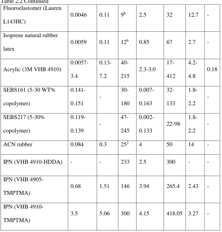
poly(vinylidene fluoride) (PVDF), copolymers and blends of PVDF, such as polyvinyl fluoride (PVF), polyamides (odd-numbered nylons), cyanopolymers, copolymers of vinylidene fluoride and vinyl fluoridem polyureas, copolymers of PVDF with trifluoroethylene (TrFE) or tetrafluoroethyelen (TFE), polythioureasm, various biopolymers (polypeptides and cyanoethyl cellulose), ferroelectric liquid crystal polymers and polymer-ceramic composites etc. [21]. Among them, PVDF is the most investigated one.
One of the most common ferroelectric polymers, PVDF, has a very simple chemical structure (–CH2-CF2-). It has four known chain conformations or polymorphs. Among them, the 𝛽
crystalline phase is most attractive form because of its piezoelectric and ferroelectric characteristics. It is formed when PVDF is mechanically deformed (or stretched) near its melting point. The all trans (TT) conformation of the 𝛽 polymorph has a large dipole moment because all of the fluorine atoms locate at the same side of the carbon, see Figure 2.3. This non-centrosymmetric structure is ideal morphology of piezoelectric crystals. The dielectric constant of PVDF is notably high, normally in the range of 6-12 [22,23].
Figure 2.3 Schematic illustration of crystal structures in 𝜷 phase of PVDF [24].
fluoride with triflouroethylene, tetrafluoroethylene or hexafluoropropylene and their blends have been widely investigated and explored [21,22,24,27–30]. It is important to note that 𝛽
phase in PVDF, does not guarantee the piezoelectric behavior unless the crystals are oriented in a certain way. Commonly, a high electric field or “poling filed” is needed to orient the crystal domains. In addition, corona discharge also has been used crystals poling. With different methods of poling, the resulting polymeric structure, ferroelectricity and chemical bond formation are different [16,31].
To further improve the electromechanical response performance, the electron irradiated poly(vinylidene fluoride-trifluotoethylene) [P(VDF-TrFE)] with improved strain response (about 4% strain) has been proposed [32,33]. After electron irradiation, the materials showed typical relaxor ferroelectric behavior. The electromechanical responses of the polar region combined with the difference of lattice strain between polar and nonpolar give the higher strain response. Later, copper-phthalocyanine (CuPc) oligomer has been introduced into P(VDF-TrFE) as fillers that dramatically enhanced the dielectric constant by about 5 times [34]. Xu et al. investigated the ferroelectric properties of poly(vinylidene fluoride-trifluoroethylene-chlorotrifluoroethylene) terpolymer [P(VDF-TrFE-CTFE)] and found that chlorotrifluoroethylene lead to the disordered ferroelectric phase, resulting in ferroelectric relaxor behavior [35]. Photo cross-linking method has also found to significantly enhance the energy density (the definition refers to section 2.2.1.4) of P(VDF-TrFE-CTFE) up to 22.5 J/cm3 at electrical field of 400 V/𝜇m owing to the reduced crystal size and intensive interface effect
Introduction of high dielectric constant ceramics (e.g. PbTiO3, BaTiO3) in ferroelectric polymers in the form of composite leads to increasing permittivity and piezoelectric coefficient
[37–39]. Other filler materials such as carbon nanotubes (CNT) [28] and palladium nanoparticles
[41] have also been used in PVDF for enhancing dielectric behavior.
Ferroelectric polymers, such as PVDF and its copolymers, combine pyroelectric and piezoelectric behavior and thus have great potential use in applications such as biomedicine, energy generation and storage, filtration, as well as in sensors and actuators. [24].
Electrostrictive Graft Elastomer
Figure 2.4 Electrostrictive graft elastomer. (a) schematic illustration of molecular structure of electrostrictive graft elastomer; (b) bimorph actuator within inactivated (middle) and activated states (left and right) made from electrostrictive graft elastomer [42].
Electrostrictive graft elastomers generally have moderate to large actuation strain (~4% under electrical field of 120 V/𝜇m) and high mechanical modulus (550-700MPa) [42]. As a result, electrostrictive graft elastomers have very high strain energy density (refer to section 2.2.1.4 for definition) (247 J/kg) compared to electrostrictive polyurethane elastomers (87 J/kg) [42]. Electrostrictive graft elastomers have been used in composites to enhance the toughness of the copolymer and thereby increasing the force output of the system [45].
Electroactive Paper
absorbed water plays an important role in strain response by inducing a non-uniform electric field and thus generating a dielectrophoretic force [51].
EAPap reportedly requires low stimulating electrical field (electrical field of 2 V/𝜇m to induce a about 3mm tip displacement of a beam actuator) and consume relatively low power consumption (a couple of ten mW/cm2 of electrical power) which is very promising for microwave driven actuators) [50,52]. However, EAPaps, produce limited and unstable displacement as well as force [53], low strain energy density (about 0.4 J/kg ([54])), are sensitivity to humidity, and have short life time etc. [48,55–57]
Liquid Crystal Elastomers
Liquid crystal elastomers (LCEs) are polymers having weakly cross-linked backbones with attached polymeric liquid crystals or mesogenic ('rod like' or anisotropic structures, with one axis appreciably longer than the other). LCEs combine the elastic properties of elastomers and the ability of self-organization of liquid crystals together and thus they manifest very unique physical properties [58]. They exhibit shape change due to change in phase and orientation of the liquid crystals under the influence of an electric field.
Figure 2.5 Different geometries of the synthesis of LCEs. (a) side-chain elastomers and (b) main-chain elastomers [58].
The electroactive response of LCEs depends on their morphology. LCEs with ferroelectric phase are triggered by the electroclinic effect in which the tilt angle of mesogens changes and hence causes deformation. In some cases, the electric field induced strain occurs in highly swollen nematic LCEs owing to nematic-isotropic (NI) phase transition (see Figure 2.6). Besides these two principles, the third actuation mechanism to use the electric power as a tool to generate thermal energy to trigger LCEs by nematic to isotropic phase transition, for instance, to add conductive wire ([59]), carbon black ([60])/ CNT into LCEs.
The main-chain elastomers are expected to generate larger strains compared to side-chain elastomers. This speculation was confirmed experimentally [61]. The main-chain elastomers show up to 400% strain while shape transition [62] and it followed by 70%[63] and 40% strain
[64] of side-chain elastomers (side-on type and end on type, respectively). In general, the LCEs are low modulus material and the low actuation strains lead to low work density. They also suffer from high dielectric loss and low efficiency [65].
2.1.2 Ionic EAPs
Ionic EAPs are a class of EAPs driven by significant volumetric changes through insertion and expulsion of counter-ions during reduction and oxidation reactions (redox cycling) through exchange of ions with electrolytes. As a result, the ionic EAPs require presence of fluid in the system. Ionic EAPs require low stimulating voltage (several volts as Table 2.1 shows) in contrast to electric EAPs. However, they have long response time and do not hold strain well. Thanks to this advantage, ionic EAPs have potential to be explored in battery-driven human-friendly devices by which the high electric field safety issues are no longer an obstacle [66]. Ionic EAPs reported in the literature include ionic polymer gel, ionic polymer-metal composite, conductive polymers, and carbon nanotubes.
2.1.2.1 Ionic Polymer Gels
Accordingly, ionic polymer gels have a huge potential to be used for synthetic organisms. The electroresponse (swelling and deswelling) of ionic polymer gels in an applied electric field is attributed to transport of hydrated ions and water in or out the polymer network [67–69]. In 1982, Tanaka et al. first reported the phenomenon of partial shrinking of rod-shaped samples of acryl acid-acrylamide copolymer gel, placed between electrodes. They explained the mechanism as a movement of negatively charged side of the gel toward the anode [70,71]. Later on it was determined that the dimensional change was indeed the result of changing ionic concentration resulting from the application of the electric field, see Figure 2.7. [69,71].
Figure 2.7 Deformation of polyelectrolyte gels under the influence of electric field [69], (a) schematic illustration of bending mechanism; (b) bending motion of the gel in the electric field.
swelling speed of ionic polymer gels is proportion to square of the electric current. In addition, theoretical investigation of the electroresponse of IPGs have been reported by many [69,76,77].
2.1.2.2 Ionomeric Polymer-Metal Composites
Typical ionic polymer-metal composites (IPMC) have a laminated structure in which two metal electrode layers form the outermost layers and in the middle there is a thin layer of ionomeric polymer membrane. The metallic electrodes typically interpenetrate the polymer membrane to produce high surface conductivity. When a voltage is applied between the two electrodes solvated mobile cations diffuse toward the oppositely charged electrodes resulting in swelling near the negative electrode and shrinkage near the positive electrode, resulting in bending deformation, see Figure 2.8.
Figure 2.8 Schematic illustration of the bending mechanism of a typical IPMC [78]
polymers, they should be able to selectively exchange ions of a single charge with their own incipient ions. One of two main categories of polymers that has been widely used is the perfluorinated alkenes with short side-chains terminated with ionic groups (e.g. sulfonate or carboxylate) for cation exchange or ammonium cations for ion exchange [79,80]. DuPont commercialized this type of ionic polymers in the early 1997 as Nafion TM that is typically fabricated from polytetrafluoroethylene (PTFE) [81]. Other commercially available products are Flemion (Asahi Glass) and Aciplex (Asahi Chemical)[78]. The other type of ionomeric polymers is the styrene/divinylbenzene-based polymer. In this type, ionic groups substitute the phenyl rings groups. These polymers with highly crosslinked structure are relatively rigid
[79,80].
When a voltage is applied to Nafion, an initial fast deformation occurs due to cationic diffusion inside the ionomeric channels (the hydrophilic ionic side groups form “spherical cluster network” and connected by narrow channels). Cations, such as Li+,Na+,K+,H+, driven by the attraction from negatively changed electrode move and drag water molecules through the ionomeric channels. The side with the higher water content expands and thus the whole system bends towards the anode. The other phenomenon is the coulombic interaction between electrodes and the fixed anionic groups in the IPMC [78]. The initial reaction is followed by a slow actuation in the same direction. However, the bending deformation is followed by “relaxation” in the opposite direction as the cations are redistributed and the dipoles reorient. IPMCs tend to drift from their position due to relaxation
There are many research works have been done to further improve the performance of IPMC. For example, instead of using metal electrode, carbonaceous electrodes (carbon black, CNT) also were explored to avoid problems of delamination and cracking associated with metal electrodes [85,86]. Nah et al. reported IPMC with nanofibrous Nafion mat which significantly improves ionic conductivity and strain speed [87]. To explore more available polymer types, Lee et al. used poly (styrene sulfonate)-grafted fluoropolymers as the polymer matrix and imidazolium-based ionic liquid as the inner solvent to show substantially larger bending displacement compared to Nafion-based actuators [88]. Vargantwar et al. reported a block ionomer with sulfonated midblocks and glassy endblocks to achieve a more stable molecular network with self-organizing feature and can be readily dissolved [89]. Jung et al. reported improved life-time of IPMC actuators by “doping” TiO2 particles in the ionomeric polymers. Also, the mechanical properties, proton conductivity and water-uptake ratio of IPMC were dramatically improved by employing fullerene to reinforce the ionomeric polymer [90]. 3D IPMC actuators have also been developed based on the novel configurations [81,91]. Also, many works have focused on the theoretical modeling of electromechanical behavior of IPMC
[92–97].
2.1.2.3 Conducting Polymers
cathode). The dimensional change in CPs is associated with the volume changes to accommodate anions and cations diffusing into and out of the polymer from the surrounding electrolyte [98,99,65].
Figure 2.9 Molecular conformational changes of conductive polymers while redox reactions
[98].
Normally, a relatively low (1-10 V) electric potential is required to trigger CPs [101] strain is in the range of 2-10% [102]. However, recent work by Kaneto et al show strain level can be as high as 40% [65] . And the work density (100 MJ/m3) of CPs is relatively high [65]. In general, CPs have some drawbacks, such as low energy efficiency (on the order of 1%) and low electromechanical coupling (less than 1%) [14], and low rates of actuation due to slow diffusion of ions [101] . The main relative advantage of CPs over other EAPs is their low operating voltage, however, degradation of the polymer as well as the electrolyte system has been noted [103] at the upper limits of the voltage (~10V) [99].
With many attractive features, CP has been developed as a wide range of polymeric actuators, such as bending/linear artificial muscles, switchable membrane, drug delivery devices, biological transducers and artificial synapses etc. [100]
2.1.2.4 Carbon Nanotubes
there are two main categories of CNTs: single-wall CNTs (SWCNT) with only one layer, and multiwall CNTs (MWCNT) [65].
Like the conductive polymer actuators, CNT actuators need to work within electrolyte solutions. The predominant cause of actuation in CNTs is electrostatic. Unlike in dielectric elastomers (see Section 2.2) the electrostatic forces here are repulsive. Application of an electric potential, between an actuating CNT electrode and counter electrode in an ion containing solution, see Figure 2.10, leads to electronic charging of the CNTs. The interface between the CNT and electrolyte has been known as the “double layer”. The accumulated like charges on the CNTs induce repulsive forces against the stiff covalent (carbon-carbon) bonds in the CNTs causing the CNTS to deform [104,105]. Interestingly, the “double layer” works as a capacitor, in which the amount of stored charges depends not only on the capacitance of CNT/electrolyte interface but also on the magnitude of the applied potential [106].
In 1999, a CNT actuator was fabricated in a “paper” form, known as “bucky-paper” [104]. A
simple bimorph cantilever actuator was formed by pasting two CNT papers to a layer of double-sided scotch tape and NaCl as the electrolyte solution as shown in Figure 2.10 (c). The simple cantilever system was able to bend alternatively to produce 0.1%-1% strain under an electric potential of -0.5 V to 1.5 V [106]
Since then many interesting actuator designs have been proposed. For example, a "nanotweezer” was developed using two MWCNTs [107,108]. A CNT yarn actuator has been
used to demonstrate reversible torsional movement [109]. Recently, an all-solid-state CNT two-ply yarn torsional actuator made by plying two twisted CNT yarns infiltrated with the solid gel electrolyte [110] has been reported.
Spinks et al used a new CNT actuator design termed as “pneumatic mechanism” to demonstrate
very large strain of 300% in the thickness direction along with 3% in-plane strain [111]. This giant strain results from the effect termed “pneumatic mechanism”. There is some gas generated beside the connection place between the electrode and the CNT sheets. The gas inflates the sheet and form many dis-shaped pores.
Carbon nanoscrolls (CNS), formed by wrapping graphite sheet into a cylinder, also show similar electroresponse feature. Under electric stimulation, CNS exhibits the scroll unwinding response due to charge injection [112].
ratio (up to 270 W/kg). And their work density is as high as about 1MJ/m3 which is similar to that of dielectric elastomers and ferroelectric polymers. CNTs are thermally stable and can survive temperature higher than 450 ℃ in air and 1000 ℃ in the inert environment. For the shortcomings, the individual CNT particles produce very limited strain due to the extremely high elastic modulus[65]. At present , CNTs normally are limited by the low electromechanical coupling and the high cost [14].
2.2 Dielectric Electroactive Polymers
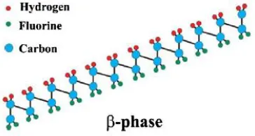
Dielectric electroactive polymers (D-EAP) constitute a class of electronic electroactive polymers with great potential. They are lightweight, low cost, and are able to generate large strains at high frequency. Because of these and other desirable qualities and their potential applications in contemporary and future technologies, D-EAPs are the most investigated actuator material in recent years. In all matters, electrons and ions move in response to applied external electric field. In conductors, the electrons and ions are able to move microscopic distances. However, in dielectrics, the charged species just move within very limited distance under the electric potential. And the deformation and the polarization are coupled. D-EAPs possess the electroresponse feature of dielectrics and low elastic modulus of elastomeric polymers[113]. This section focuses on D-EAPs in terms of the working principles, characterization techniques, materials commonly used including electrodes actuator design, and their important performance and potential applications.
simple. In a typical actuator configuration, a layer of soft D-EAP is sandwiched between two layers of compliant electrodes. On application of an electric potential across the electrodes, the attractive force between the opposite charges and the repulsive force between the like charges result in deformation of the dielectric elastomer. This electrostatic force induced deformation is known as “Maxwell stress,” described in detail in section 2.1.1.1. In addition to Maxwell stress effect, electrostriction related to the polarization in the dielectric material also plays a role in the electroresponse of D-EAPs. Electrostriction effect is usually small and is considered insignificant in exploring the mechanism behind electromechanical response of D-EAPs.
Figure 2.11 Principle of operation of D-EAPs
2.2.1 Characteristic Parameters
it is important to clearly understand this performance metric and the trade-offs that are often necessary for many applications. In the following, these parameters are defined and discussed in terms of published data on various D-EAP materials.
2.2.1.1 Actuation Stress and Blocking Force
The compressive stress (P) generated in a D-EAPs is expressed in terms of relevant parameters
[114,115].
𝑃 = 𝜀𝜀0𝐸2 = 𝜀𝜀
0(𝑉/𝑧)2 Equation 2.6
where 𝜀 and 𝜀0 is relative permittivity of free space and the material, respectively, 𝐸 is the applied electric field, 𝑉 is the applied voltage, and z is the thickness of the D-EAPs.
Equation 2.6 assumes that the dielectric behavior of the elastomer remains unaltered under strain. Nevertheless, it is not always true. For example, the acrylic elastomers (3M, VHBTM, 4910) show lower dielectric constant under a large strain (dielectric constant drops to 4.45 from 4.7 when the prestretch ration increases to 15 from 0) [116]. So it is necessary to take the electrostriction effect into consideration. Accordingly, the in-plane stress and the compressive stress can be expressed as Equation 2.7 and Equation 2.8 respectively. In these two equations,
𝛼1 and 𝛼2 denote the dielectric property change factors in shear and bulk deformations. They
are related to the electrostriction effect. So components in these equations containing the two factors represent the contribution of the electrostriction and the rest is related to Maxwell effect
[117].
𝜎𝑥𝑥 = 𝜎𝑦𝑦 = 1 2𝜀𝜀0𝐸
2(1 +𝛼1
𝜀 )
𝜎𝑧𝑧= −1 2𝜀𝜀0𝐸
2(1 −𝛼1 + 𝛼2
𝜀 )
Equation 2.8
2.2.1.2 Blocking Force
The force required to return a fully activated actuator to its original state is defined as blocking force. In a planar actuator, it is the in-plane force exerted toward the inactive area at the boundary. Alternatively, it is the force generated by a linear actuator held at a constant length [118]. Considering isochoric deformation of the material under the effect of Maxwell stress only, the blocking force can be calculated from the actuator’s initial and activated dimensions.
If a planar actuator having dimensions, (𝑋0×𝑌0×𝑍0) changes to (𝑋×𝑌×𝑍) upon activation, see Figure 2.12, and the ratio between 𝑋0 and 𝑋, 𝑌0 and 𝑌 are 𝛼𝑥 and 𝛼𝑦, respectively. Then the blocking force (Fy) in y direction can be expressed as [116].
Figure 2.12 The dimension change of D-EAP under actuation.
𝐹𝑦 = 𝜎𝑀𝑎𝑥𝑤𝑒𝑙𝑙×𝐴 = 𝜀𝜀0𝐸2×(𝑋𝑍) = 𝜀𝜀
0𝐸2×𝑋0×𝛼𝑥×
𝑍0 𝛼𝑥𝛼𝑦
= 𝜀𝜀0𝐸2
𝑋0𝑍0 𝛼𝑦
2.2.1.3 Actuation Strain
The electrostatic stress through the thickness direction as well as the in-plane repulsive forces engenders in-plane actuation strain in the D-EAP. In general, the actuation strain has been expressed both in terms of linear or areal actuation strains. The linear strain is the ratio between the change in length and the original length along any direction of the active area. For example, for the geometry as shown Figure 2.12, the linear strain can be expressed by Equation 2.10. Alternatively, the thickness strain can be calculated from the areal strain.
𝑆𝑥 =𝑋 − 𝑋0
𝑋0 ×100%
Equation 2.10
Similarly, the areal actuation strain is the ration between the increased area and the original area of the active part as Equation 2.11.
𝑆𝑎𝑟𝑒𝑎= 𝑋𝑌 − 𝑋0𝑌0
𝑋0𝑌0 ×100%
Equation 2.11
The in-plane strain is normally tested by a well-known circular actuator set-up as shown in Figure 2.13. The rigid frame is needed as the support of pre-stretched film. The circular active area just occupying a small proportion of the whole area is to eliminate the boundary arcing
Figure 2.13 Schematic illustration of circular strain set-up and photographs of acrylic elastomer under the circular strain testing.
2.2.1.4 Elastic Strain Energy Density
Elastic strain energy density (𝑢𝑒) is a critical performance parameter of actuator materials. It is defined as a work output capability or energy output in one actuation cycle per unit volume of the material excluding the overheads (power supply, electrode, packaging, etc.) [120]. This parameter is very useful to evaluate the performance of an actuator because it is size independent. In terms of material properties, and assuming small strain, it can be expressed as,
𝑢𝑒 =1 2𝑃𝑆𝑧=
1 2𝑌𝑆𝑧
2 Equation 2.12
where P is the compressive stress, 𝑆𝑧 is the strain in thickness direction and 𝑌 is the modulus of the materials.
For large strain situations, the active area increases and the formula of elastic energy density is expressed as [115].
𝑢𝑒 = 𝑌[𝑆𝑍− ln(1 + 𝑆𝑍)] Equation 2.13
2.2.1.5 Electromechanical Coupling Efficiency
Electromechanical coupling efficiency (𝑘2, following the nomenclature for piezoelectrics) is another useful parameter and is calculated as a ratio of the generated work to input energy. Therefore coupling efficiency is an expression of the proportion of the electric energy converted into mechanical energy in one working cycle. Normally, 𝑘2 is derived from the capacitance of the D-EAP actuators by using the electrostatic model assuming the dielectric constant remains the same upon actuation [115]. The calculation for coupling efficiency begins with the capacitance (C) of D-EAPs actuator;
𝐶 =𝑄
𝑈 =
𝜀𝜀0𝐴
𝑧 =
𝜀𝜀0𝑉 𝑧2
Equation 2.14
Where Q is the total charge stored, U is the electric potential between electrodes, V and A is the total volume and active area of the capacitor or actuator respectively.
The electric energy of the actuator (W) expressed in terms of capacitance is,
𝑊 = 𝑈𝑄 =𝑄
2
𝐶
Equation 2.15
Assuming state 1 denotes the stage at the beginning of the application of electric field, and 2 is the stage when D-EAPs show mechanical response. If a viscoelastic loss of the polymer is ignored, the difference of electric energy between these two states is equal to the converted electrical energy to mechanical energy.
∆𝑊 = 𝑊2− 𝑊1 =
𝑄2 𝐶2
−𝑄
2
𝐶1 Equation 2.16
∆𝑊 𝑊1
= 𝑄2
𝐶2 −
𝑄2
𝐶1
𝑄2
𝐶1
= 𝑧2
2 − 𝑧
12
𝑧12
=[𝑧1(1 + 𝑆𝑍)]
2
𝑧12
− 1 = 𝑆𝑍2+ 2𝑆𝑍
Equation 2.17
Needless to note, actuator materials with high coupling efficiency are desirable.
The electromechanical coupling efficiency is determined by the mechanical and electrical loss in the elastomers. The mechanical loss in D-EAPs is normally greater that the electrical loss [4,121]. The mechanical efficiency represents the ability of elastomers to remain their elasticity, a parameter that is inversely proportional to the loss tangent. In viscoelastic materials, loss tangent is a measure of mechanical damping in the material and is measured as a ratio of the loss modulus to the storage modulus obtained through dynamic mechanical analysis of materials.
2.2.1.6 Electric Breakdown Strength
The electric field can be applied to D-EAPs is not infinite. There is a maximum value known as the breakdown strength at which D-EAPs have a finite conductivity owing to charge generated in the materials. At the electric breakdown strength, the electric circuit short occurs and there is “burning” phenomenon on the film. This failure normally is unrepairable because
that it propagates quickly and the opposite electrodes surrounded it would be conductive. So a higher electric breakdown strength is desired in principle [116].
2.2.1.7 Effects of Prestrain on Actuation Performance
the response speed and break down strength. On the other hand, it reduces the deforming ability of the elastomers [122].
In order to systematically investigate the influence of the prestrain on overall performance of D-EAPs actuators, Choi and coworkers experimentally studied the relationships between properties of VHB elastomers (one of the most used acrylic D-EAPs, more detail can be found in section 2.2.2.2) and the prestrain [122].
First of all, they examined the effect of prestrain on stiffness of polymers. In this work, VHB was firstly stretch to a certain strain (from 100% to 500%) and kept for a while. Then in the second step, the same sample was continuously stretched by the increment of 100% strain. For a compare purpose, one uninterrupted tensile testing was conducted with maximum strain of 600%. Figure 2.14 shows the results. Interestingly, it is found that after the first step stretching the stress-strain curves of the second step are very similar to the one of sample of uninterrupted testing. This means that the prestrain almost does not have influence on the inherent elastic modulus of the materials. However, the first strain magnitude surely decides the second step young’s modulus. For example, the initial modulus in the second stretching step following a 100% strain in the first step (the black dash line) is higher than that of the sample following a 400% prestrain in first step (the yellow dashed line). This suggests that prestrain is not always stiffening elastomers. In this work, VHB elastomers with prestrains of 200%-500% have similar stiffness, which is smaller than those with prestrains less than 200% (plateau effect
Figure 2.14 Stress-strain curves of VHB elastomers with different strain and relaxation [122]
In addition, the permittivity of acrylic elastomers also is influenced by prestrain. Figure 2.15 illustrates the experimental results: VHB with the higher prestrain has smaller dielectric constant on contrast in whole of the frequency range (1-105 Hz). This phenomenon has been usually neglected which is actually large enough and not negligible.
While the prestrain increases, the thickness of elastomer decreases. The thinner elastomers commonly have a lower breakdown voltage [116,124]. However, the breakdown strength of the thinner elastomers is higher because the decrease of thickness surpasses the decrease of breakdown voltage, see Figure 2.16. In addition, researchers claimed that the electric breakdown strength in cross polymer chains direction is higher than the one along chains. Because that in the cross-chain direction there are more D-EAP chains working as obstacles of avalanching electrons. On contrast, along chain direction there are less polymer atoms perpendicularly facing to electrons. When applying in-plane prestrain, more polymer chains orient horizontally so that the electric breakdown strength of D-EAPs increases [116].
Figure 2.16 Effect of prestrain on electric breakdown strength and voltage [116].
Figure 2.17 shows two acrylic elastomers films having different initial thicknesses but stretched to the same thickness by applying different levels of prestrain [122]. The film with higher prestrain produced lower actuation strain at the same electric field but significantly higher dielectric strength and thereby larger actuation strain at failure.
Figure 2.17 Comparison of actuation strain of VHB films of different initial thickness prestrained to have the same initial thickness [122]
Figure 2.18 Mechanical efficiency and loss tangent of acrylic elastomers at different levels of prestrain and frequency [121]
efficiency [131]. The IPN network developed using prestrained acrylic elastomer film, VHB, has been stabilized by 18.3% second polymer network. The VHB network successfully retained 275% prestrain from the starting prestrain of 400% [129,130]. Suo and Zhu established a theoretical model to simulate interpenetrating networks with long and short chains to have a better understanding of the interlocking mechanism [133].
Figure 2.19 Schematic illustration of the fabrication process of an IPN elastomer film. (a) an acrylic film before processing; (b) after 400% biaxial prestrain; (c) curable additives are added into the prestrained film and cured, forming interpenetrating network of a highly crosslinked polymer; (d) after the external stress is removed, the interpenetrating network preserves most of the prestrain of the acrylic film [130].
In a similar effort, Shankar et al. developed polystyrene-block-poly(ethylene-co-butylene)-blockpolystyrene (SEBS) triblock copolymer swollen with midblock-selective solvent
2.2.1.8 Instability and Failure
The instability of D-EAPs mainly roots in the “pull-in effect” [136]. The instability or “pull-in
effect” occurs in a D-EAPs when its thickness falls below a certain value as the electrostatic stress becomes larger than the materials’ compressive strength. Beyond this critical point, the pressure further flattens the film leading to a larger electrical field across the film and much higher pressure resulting in “positive feedback”. The process finally leads to instability and catastrophic failure of the film. Figure 2.20 shows the visible wrinkled morphology on the surface of D-EAPs before failure. Due to the extremely large local deformations, wrinkles eventually bring in either mechanical failure or dielectric breakdown of the materials.
Figure 2.20 Film surface morphology during pull-in instability [136]
to make the true electric extremely large. At this point, the potential (Φ ) needs to maintain the charge drops. As Q increases further, the flattened elastomer film becomes mechanically stiff in compression and thus Φ again increases with Q. The first peak of Φ has been known as start of pull-in instability. The process of thinning of the elastomer is discontinuous because of the non-uniform distribution of charge and the applied voltage. If Φ is held constant, the elastomer will show electrochemical hysteresis and a sudden reduction of the thickness like ferroelectrics. If Q is maintained, there will be a state in which the thin and thick regions of the elastomers exist at the same time under the certain voltage. And the thin region with larger area will be constrained by the surrounding thick regions so that wrinkles appear [137]. According to the theoretical model, the thin parts tend to expand to the thick regions at a constant voltage [138].
Figure 2.21 Schematic illustration of the voltage-charge curve of a layer of an elastomer dielectric where 𝚽 is electric voltage and Q is stored charged in the electrodes [137]
Zhao and Suo also investigated the pull-in instability of D-EAPs using free energy theory
[141]. Díaz-Calleja et al. further explored the pull-in effect and the electromechanical stability of neo-Hookean silicones [142]. Meanwhile, Liu et al. also modified Zhao’s model and
Díaz-Calleja’s model through using Mooney–Rivlin elastic strain energy function with two materials constants [143–145]. Later, Leng et al. proposed a nonlinear expression of the permittivity as the function of strains and built the relationship between critical nominal electric field, critical true electrical field, nominal stress and principle stretch ratio [140]. Furthermore, Xu at al. used the concept of total stress to broaden the availability of expression for the critical stability electric field of Zhan and Suo which can be used for general hyperplastic material models
[146]. Also, for specific shaped D-EAP devices, their instability has been investigated as well, for example, the multilayered soft dielectrics [147] and tube actuators [113].
conductivity increases with the temperature (e.g. polyurethane). The increase in temperature may be dramatic because of the positive feedback mentioned before. Discharge of gas at the surface and/or inside of the elastomers could also induce the electric breakdown. The defects in the form of air voids in elastomers are normally the places where sparks begin. Thickness variation in elastomers may also produce extremely high local electric field. Poor circuit connections may lead to failure due to local joule heating [148].
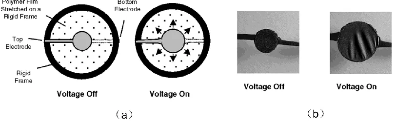
Zhao and Suo categorized three types failure in dielectrics based on their voltage-stretch response, see Figure 2.22 [150,151]. Type I response occurs in stiff dielectrics, such as ceramics or glassy polymers. These materials fail because of electrical breakdown; Type II is the soft dielectrics, such as elastomers, normally fail due to the electromechanical instability; Type III is a special class of dielectrics. They are able to survive the electromechanical instability and further deform to reach a giant strain level.
Figure 2.22 Working principle of dielectric elastomers transducers and three types of failure mechanisms. (a) a membrane of dielectric elastomer subject to a voltage reduces thickness and expands area. (𝚽 denotes applied voltage and 𝝀 is the deformation ratio). The voltage-stretch curve typically is not monotonic. (b)-(d) three types of dielectrics are differentiated by where the two curves 𝚽(𝝀) and 𝚽𝑩(𝝀) intersect, where 𝚽𝑩(𝝀) is the breakdown voltage as a
Type III dielectrics should have the following features, (1) at small strain the materials should be soft; (2) at modest strain 𝜆𝑙𝑖𝑚 the dielectrics should stiffen steeply, here the modest strain is emphasized which means the stretch should not be excessive as shown in Figure 2.23 (a). In order to achieve these features, polymeric composites (see Figure 2.23 (b)) or polymers with special molecular structures were proposed (see Figure 2.23 (c-e)).
Figure 2.23 Ideal stress-strain curve and molecular structure of dielectrics with Type III failure type. (a) stress-strain curve of a membrane under biaxial stress; (b) fiber embedded in a compliant matric; (c) a network of polymers with folded domains; (d) a network of polymers with side chains; (e) a network of polymers swollen with
![Table 2.1 Comparison of the properties of EAP, SMA and EAC [2]. EAP SMA](https://thumb-us.123doks.com/thumbv2/123dok_us/1224349.1154200/29.612.88.544.73.421/table-comparison-properties-eap-sma-eac-eap-sma.webp)
![Figure 2.1 Classification of Electroactive Polymers [2]](https://thumb-us.123doks.com/thumbv2/123dok_us/1224349.1154200/30.612.134.503.72.446/figure-classification-of-electroactive-polymers.webp)
![Figure 2.6 Schematic illustration of anisotropic phase of liquid crystal part transfers to the isotropic phase with increasing temperature and dimensional change [61]](https://thumb-us.123doks.com/thumbv2/123dok_us/1224349.1154200/40.612.219.409.73.207/schematic-illustration-anisotropic-transfers-isotropic-increasing-temperature-dimensional.webp)
![Figure 2.29 Chemical structure of thermoplastic SEBS elastomer [214]](https://thumb-us.123doks.com/thumbv2/123dok_us/1224349.1154200/78.612.200.406.77.182/figure-chemical-structure-thermoplastic-sebs-elastomer.webp)
![Table 2.2 Maximum response of representative elastomers [7] Elastic](https://thumb-us.123doks.com/thumbv2/123dok_us/1224349.1154200/80.612.91.540.81.593/table-maximum-response-representative-elastomers-elastic.webp)