555-233-506
Comcode 108678798
Issue 1
April 2000
Enterprise Communication Server
Release 8.2
Printed in U.S.A. Notice
Every effort was made to ensure that the information in this book was complete and accurate at the time of printing. However, information is subject to change.
Your Responsibility for Your System’s Security
Toll fraud is the unauthorized use of your telecommunications system by an unauthorized party, for example, persons other than your com-pany’s employees, agents, subcontractors, or persons working on your company’s behalf. Note that there may be a risk of toll fraud associated with your telecommunications system and, if toll fraud occurs, it can result in substantial additional charges for your telecommunications services.
You and your system manager are responsible for the security of your system, such as programming and configuring your equipment to pre-vent unauthorized use. The system manager is also responsible for reading all installation, instruction, and system administration docu-ments provided with this product in order to fully understand the fea-tures that can introduce risk of toll fraud and the steps that can be taken to reduce that risk. Lucent Technologies does not warrant that this product is immune from or will prevent unauthorized use of com-mon-carrier telecommunication services or facilities accessed through or connected to it. Lucent Technologies will not be responsible for any charges that result from such unauthorized use.
Lucent Technologies Fraud Intervention
If you suspect that you are being victimized by toll fraud and you need technical support or assistance, call Technical Service Center Toll Fraud Intervention Hotline at 1 800 643-2353.
Federal Communications Commission Statement
Part 15: Class A Statement. This equipment has been tested and found to comply with the limits for a Class A digital device, pursuant to Part 15 of the FCC Rules. These limits are designed to provide reason-able protection against harmful interference when the equipment is operated in a commercial environment. This equipment generates, uses, and can radiate radio-frequency energy and, if not installed and used in accordance with the instructions, may cause harmful interfer-ence to radio communications. Operation of this equipment in a resi-dential area is likely to cause harmful interference, in which case the user will be required to correct the interference at his own expense.
Part 68: Network Registration Number. This equipment is registered with the FCC in accordance with Part 68 of the FCC Rules. It is identi-fied by FCC registration number AS593M-13283-MF-E.
Part 68: Answer-Supervision Signaling. Allowing this equipment to be operated in a manner that does not provide proper answer-supervi-sion signaling is in violation of Part 68 Rules. This equipment returns answer-supervision signals to the public switched network when:
• Answered by the called station • Answered by the attendant
• Routed to a recorded announcement that can be administered by the CPE user
This equipment returns answer-supervision signals on all DID calls forwarded back to the public switched telephone network. Permissible exceptions are:
• A call is unanswered • A busy tone is received • A reorder tone is received
This digital apparatus does not exceed the Class A limits for radio noise emissions set out in the radio interference regulations of the Canadian Department of Communications.
Le Présent Appareil Nomérique n’émet pas de bruits radioélectriques dépassant les limites applicables aux appareils numériques de la class A préscrites dans le reglement sur le brouillage radioélectrique édicté par le ministére des Communications du Canada.
Trademarks
See the preface of this document.
Ordering Information
Call: Lucent Technologies BCS Publications Center
USA 1 888 582-3688
USA Fax 1 800 566-9568 Canada +1 317-322-6619 Europe, Middle East, Africa +1 317-322-6416 Asia, Caribbean, China, Latin America, and
the Pacific Region +1 317-322-6411 International Fax +1 317 322-6699
Write: Lucent Technologies BCS Publications Center 2855 N. Franklin Road
Indianapolis, IN 46219
Order: Document No. 555-233-506 Comcode 108678798 Issue 1, April 2000
For additional documents, refer to ‘‘References’’ on page 21-1604
You can be placed on a standing order list for this and other documents you may need. Standing order will enable you to automatically receive updated versions of individual documents or document sets, billed to account information that you provide. For more information on stand-ing orders, or to be put on a list to receive future issues of this docu-ment, contact the Lucent Technologies Publications Center.
European Union Declaration of Conformity
The “CE” mark affixed to the DEFINITY® equipment described in this book indicates that the equipment conforms to the following Euro-pean Union (EU) Directives:
• Electromagnetic Compatibility (89/336/EEC) • Low Voltage (73/23/EEC)
• Telecommunications Terminal Equipment (TTE) i-CTR3 BRI and i-CTR4 PRI
For more information on standards compliance, contact your local dis-tributor.
Comments
To comment on this document, return the comment card at the front of the document.
Acknowledgment
Contents
iii
Contents
Contents iii
About this document xv
■ Overview xv
■ Purpose xvi
■ Audience xvi
■ Reason for reissue xvi
■ How to use this document xvi
■ Organization xvi
■ Task-related information xviii
■ Feature-related information xix
■ Conventions used in this document xix
■ Trademarks and service marks xxi
■ How to get this book on the web xxii
■ How to order more copies xxii
■ How to get help xxiii
■ Tell us what you think xxiii
1
System basics 1■ Logging into the system 1
■ Logging in with Access Security Gateway 3
■ Logging off the system 4
■ Setting command permissions 5
■ Establishing daylight savings rules 7
■ Setting the system date and time 9
■ Using the bulletin board 11
■ Saving translations 13
2
Introduction to the DEFINITY system 17■ Understanding your configuration 17
■ Understanding the dial plan 19
■ Adding feature access codes 21
■ Controlling the calls your users can make and receive 22 ■ Controlling the features your users can access 24
■ System-wide settings 25
Contents
iv
■ Administering treatment for denied calls 26
■ Setting up Music-on-Hold 27
■ Providing service for multiple tenants 29
■ Receiving notification in an emergency 31
■ Notifying a digital pager of an emergency 34
■ Other useful settings 35
3
Managing phones 37■ Adding new phones 37
■ Using templates to add phones 41
■ Using an alias 42
■ Customizing your phone 43
■ Upgrading phones 44
■ Swapping phones 45
■ Using TTI to move phones 46
■ Removing phones 49
■ Adding a fax or modem 51
■ Adding a DEFINITY IP Softphone 52
4
Managing phone features 57■ Adding feature buttons 57
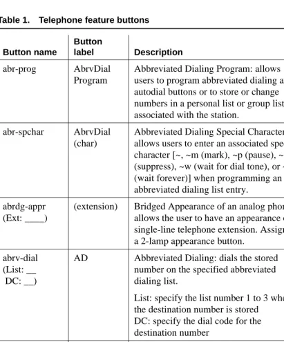
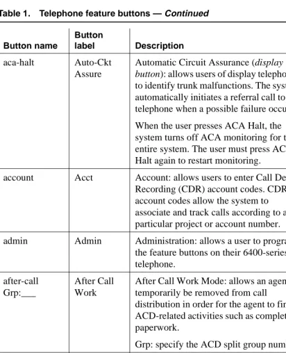
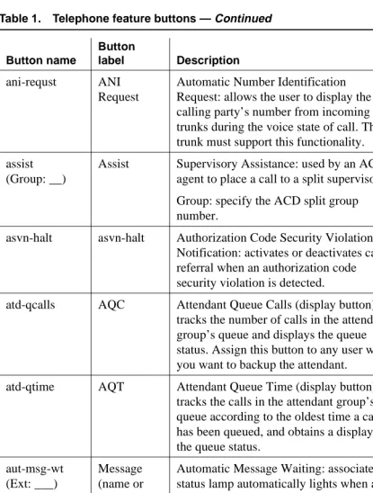
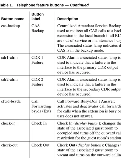
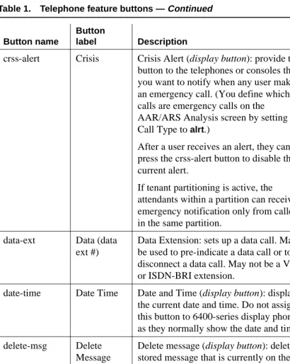
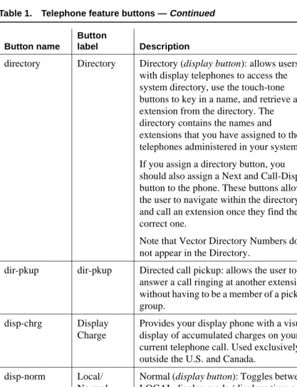
■ Telephone feature buttons 58
■ Adding abbreviated dialing lists 79
■ Setting up bridged call appearances 84
■ Setting up Terminal Self Administration 87
5
Managing your attendant consoles 91■ Overview 91
■ Adding an attendant console 95
■ Attendant console feature buttons 97
■ Removing an attendant console 104
■ Setting console parameters 105
■ Providing backup for an attendant 106
6
Managing displays 109■ Displaying caller information 109
■ Displaying ANI calling party information 109
Contents
v
■ Changing the display language 112
■ Setting up directory buttons 115
7
Handling incoming calls 117■ Setting up basic call coverage 117
■ Setting up advanced call coverage 121
■ Setting up call forwarding 127
■ Setting up night service 132
■ Adding call pickup 146
■ Managing hunt groups 152
■ Managing vectors and VDNs 157
■ Understanding Automatic Call Distribution 169
■ Assigning a terminating extension group 170
8
Routing outgoing calls 173■ World class routing 173
■ Managing calling privileges 174
■ Assigning ARS FAC 174
■ Displaying ARS analysis information 175
■ Understanding ARS analysis 175
■ Setting up multiple locations 182
■ Routing with multiple locations 184
■ Modifying call routing 186
■ Overriding call restrictions 190
■ Defining ARS Partitions 191
■ Setting up time of day routing 194
■ Setting up shortcut dialing 196
9
Managing multimedia calling 201■ Multimedia Applications Server Interface 201
■ Multimedia Call Handling 230
■ Understanding the multimedia complex 249
■ Enhanced Mode MM complex 263
10
Setting up telecommuting 285■ Configuring DEFINITY ECS for telecommuting 285
■ Setting up Personal Station Access 287
Contents
vi
■ Assigning coverage options 291
■ Setting up call forwarding 292
■ Assigning an extender password 294
■ Installing home equipment 295
■ Setting up remote access 297
■ Training users 301
11
Enhancing system security 305■ Basic security 306
■ Preventing toll fraud 306
■ Physical security 309
■ System security checklist 309
■ Adding logins and passwords 314
■ Changing a login 317
■ Displaying a login 318
■ Removing a login 319
■ Using access security gateway 319
■ Changing login permissions 324
■ Changing passwords 326
■ Using busy verify 327
■ Setting up security violations notification 328
■ Setting up authorization codes 331
■ Dealing with security violations 334
12
Managing trunks 337■ Tips for working with trunk groups 337
■ Adding a CO, FX, or WATS trunk group 340
■ Adding a DID trunk group 343
■ Adding a DIOD trunk group 345
■ Adding a PCOL trunk group 345
■ Adding a Tie or Access trunk group 348
■ Setting up digital trunks 351
■ Adding trunks to a trunk group 355
■ Removing trunks from a trunk group 357
■ Removing trunk groups 358
■ Inserting and absorbing digits 359
Contents
vii
■ Administering trunks for listed directory numbers 362
13
Managing announcements 365■ Understanding announcements 365
■ Adding announcement data modules 365
■ Adding announcement extensions 367
■ Recording announcements 368
■ Saving announcements 369
■ Copying announcements 370
■ Restoring announcements 371
■ Deleting and erasing announcements 372
■ Setting up continuous-play announcements 373
14
Managing group communication 375■ Setting up voice paging over loudspeakers 375
■ Setting up chime paging over loudspeakers 378
■ Paging over speakerphones 381
■ Paging users who are on active calls 383
■ Using phones as intercoms 385
■ Observing calls 387
15
Managing data calls 391■ Types of data connections 391
■ Data Call Setup 392
■ Default Dialing 398
■ Alphanumeric Dialing 399
■ Data Hotline 400
■ Data Privacy 401
■ Data Restriction 402
■ Data-Only Off-Premises Extensions 404
■ Data Modules — general 405
■ Administered Connection 408
■ Modem Pooling 415
■ PC Interface 417
■ Wideband Switching 421
■ CallVisor Adjunct-Switch Application Interface 434
Contents
viii
16
Collecting billing information 439■ Collecting information about calls 439
■ Recording calls between users on the same switch 442
■ Tracking calls by account code 443
■ Forcing users to enter account codes 444
■ Receiving call-charge information 446
■ Viewing call charge information 449
17
Screen reference 451■ AAR and ARS Digit Analysis Table 451
■ AAR and ARS Digit Conversion Table 455
■ Abbreviated Dialing List 459
■ Access Endpoint 467
■ Administered Connection 471
■ Alias Station 476
■ Alphanumeric Dialing Table 478
■ Announcements/Audio Sources 480
■ ARS Toll Table 483
■ Attendant Console 484
■ Authorization Code — COR Mapping 497
■ Bulletin Board 499
■ Call Vector 501
■ CAMA Numbering Format 506
■ CDR System Parameters 508
■ Class of Restriction 520
■ Class of Service 532
■ Code Calling IDs 535
■ Command Permission Categories 536
■ Console Parameters 540
■ Coverage Answer Group 550
■ Coverage Path 551
■ Crisis Alert System Parameters 555
■ Data modules 558
■ Date and Time 589
■ Daylight Savings Rules 591
Contents
ix
■ Digit Absorption 598
■ DS1 Circuit Pack 599
■ Extended Pickup Group 617
■ Extensions Administered
to have an MCT-Control Button 618
■ Feature Access Code 619
■ Feature-Related System Parameters 632
■ Group Paging Using Speakerphone 681
■ Hospitality 683
■ Hunt Group 696
■ Intercom Group 720
■ Inter-Exchange Carrier (IXC) Codes 721
■ Intra-Switch CDR 723
■ IP Trunk Configuration Manager 724
■ ISDN trunk group 738
■ ISDN Numbering — Private 772
■ ISDN Numbering — Public/ Unknown 775
■ ISDN-BRI Trunk Circuit Pack 777
■ Language Translations 786
■ Listed Directory Numbers 800
■ Locations 802
■ Login Administration 804
■ Loudspeaker Paging 810
■ Mode Code Related System Parameters 813
■ Modem Pool Group 817
■ Multifrequency-Signaling-Related
System Parameters 823
■ Music Sources 845
■ Packet Gateway Board 846
■ Partition Route Table 848
■ Personal CO Line Group 848
■ Pickup Group 852
■ PRI Endpoint 853
■ Remote Access 857
■ Remote Call Coverage Table 863
Contents
x
■ Route Pattern 865
■ Second Digit Table 874
■ Security-Related System Parameters 875
■ Site Data 882
■ Station 882
■ System Parameters Call Coverage / Call Forwarding 911
■ System Parameters Country-Options 918
■ System Parameters Customer-Options 928
■ System Parameters OCM
Call Classification 948
■ Telecommuting Access 951
■ Tenant 951
■ Terminal Parameters 954
■ Terminating Extension Group 959
■ Time of Day Coverage Table 962
■ Time of Day Routing Plan 963
■ Toll Analysis 964
■ Trunk Group 967
■ Vector Directory Number 1033
18
Command reference 104119
Phone reference 1065■ Multibutton electronic telephones 1066
■ 500 telephones 1067
■ 2500-series telephones 1067
■ 6200-series telephones 1067
■ 6400-series telephones 1071
■ 7100-series telephones 1075
■ 7300-series telephones 1075
■ 731x-series hybrid telephones 1078
■ 7400-series telephones 1083
■ ISDN telephones (7500s & 8500s) 1100
■ 8110 telephones 1105
■ 8400-series telephones 1105
■ CALLMASTER telephones 1112
Contents
xi
■ DEFINITY Internet Protocol (IP) Softphones 1119
20
Features and technical reference 1123■ AAR and ARS partitioning 1123
■ AAR/ARS shortcut dialing 1125
■ Abbreviated Dialing 1129
■ Access security gateway 1131
■ Administered Connections 1133
■ Administrable Language Displays 1138
■ Alternate facility restriction levels 1140
■ Answer detection 1141
■ Attendant Features 1143
■ Audible Message Waiting 1152
■ Authorization codes 1152
■ Automated Attendant 1157
■ Automatic Callback 1159
■ Automatic circuit assurance 1162
■ Automatic Number Identification 1165
■ Automatic routing — general 1167
■ Barrier codes 1172
■ Bridged Call Appearance 1174
■ Busy Indicator 1188
■ Busy Verification 1189
■ Call Charge Information 1195
■ Call Coverage 1200
■ Call Detail Recording 1221
■ Call Forwarding 1278
■ Call Park 1287
■ Call Pickup 1289
■ Call Waiting Termination 1294
■ Call-by-Call Service Selection 1295
■ Calling Party/Billing Number 1302
■ Calling Party Number Restriction 1303
■ Class of Restriction 1304
■ Conference 1309
Contents
xii
■ Crisis Alert 1313
■ Dial Plan 1315
■ Distinctive Ringing 1317
■ DS1 Trunk Service 1317
■ Emergency Access to the Attendant 1323
■ Emergency Transfer 1326
■ Extended User Administration of Redirected Calls 1327 ■ Facility and Non-Facility Associated Signaling 1331 ■ Facility restriction levels and
traveling class marks 1338
■ Generalized route selection 1340
■ Group paging 1343
■ Hospitality features 1346
■ Hunt Groups 1368
■ Incoming Call Line Identification 1376
■ Intercom 1377
■ Internal Automatic Answer 1379
■ IP trunk service 1383
■ ISDN service 1394
■ Leave Word Calling 1408
■ Line Lockout 1410
■ Listed Directory Numbers 1411
■ Look-Ahead routing 1413
■ Loss Plans 1415
■ Loudspeaker paging 1416
■ Malicious Call Trace 1421
■ Messaging Server Interface 1426
■ Misoperation Handling 1429
■ Modem Pooling 1433
■ Multiappearance Preselection and Preference 1436
■ Multifrequency Signaling 1438
■ Night Service 1444
■ Off-Premises Station 1453
■ PC Interface 1454
■ Personal Station Access 1458
Contents
xiii
■ Pull Transfer 1463
■ Recorded Announcements 1464
■ Recorded Telephone Dictation Access 1466
■ Remote Access 1466
■ Ringer Cutoff 1474
■ Ringing — Abbreviated and Delayed 1475
■ Security violations notification 1479
■ Service observing 1483
■ Single-Digit Dialing and Mixed Station Numbering 1487
■ Station Hunting 1491
■ Station Security Codes 1498
■ Telephone Displays 1499
■ Temporary Bridged Appearance 1534
■ Tenant Partitioning 1536
■ Terminal Translation Initialization 1547
■ Terminating Extension Group 1551
■ Time of Day Routing 1553
■ Transfer 1554
■ Transfer — Outgoing Trunk to
Outgoing Trunk 1557
■ Transfer — Trunk-to-Trunk 1560
■ Trunk Flash 1562
■ Trunks and Trunk Groups 1564
■ Voice Message Retrieval 1573
■ Voice Messaging Systems 1576
■ Whisper paging 1582
■ Wideband Switching 1587
■ World-Class Tone Detection and Generation 1601
21
References 1604■ Basic DEFINITY ECS documents 1604
GL
Glossary and abbreviations 1612Contents
About this document
xv Overview
About this document
Overview
This document describes the DEFINITY Enterprise Communications Server (ECS) Release 8 administration, and includes all incremental releases up to and including Release 8.2. You may also want to see the DEFINITY ECS Change
Description to see what is new as of R8.2.
NOTE:
This book contains information previously contained in the DEFINITY ECS
Administration and Feature Description and DEFINITY ECS Implementation books.
DEFINITY ECS is a family of cost-effective digital communication systems. These systems:
■ route voice and data information between various endpoints (telephones,
terminals, computers)
■ provide highly robust networking capabilities
■ include an extensive set of standard features including attendant consoles,
voice processing interface, call coverage, DS1 (T1 and E1) connectivity, hospitality support, recorded announcements, and trunk-to-trunk transfer
■ provide flexibility and allow for the addition of optional features and/or
About this document
xvi Purpose
Purpose
This document provides an overall reference for planning, operating, and
administering your DEFINITY ECS. The book is divided into three volumes that present information on how to perform administrative tasks, how to complete administrative screens, and more detailed information on individual features.
This document does not contain information about how to install, maintain, repair, or troubleshoot the switch. See ‘‘References’’ on page 1604 for a list of related DEFINITY ECS documents.
Audience
This document is intended for DEFINITY ECS system administrators and managers, users interested in information about specific features, and Lucent Technologies personnel responsible for planning, designing, configuring, selling, and supporting the system.
Reason for reissue
This document is updated to include DEFINITY ECS Release 8.2 information. It also presents a restructure of the information contained in the DEFINITY ECS
Administration and Feature Description to present standard administration
procedures and allow the reader to make decisions about what actions to take to accomplish administrative goals.
How to use this document
Use this document as a guide to completing administrative procedures and as a reference document. If you are interested in information about a particular task, screen, or feature, use the index or table of contents to locate the page number where the information is described.
Organization
The first volume of this document provides step-by-step tasks for the
About this document
xvii Organization
The following list describes the sections in this book.
‘‘System basics’’tells you how to log in and log off, set permissions for others who use the administration terminal, set daylight savings rules, set the system date and time, post messages, and back up the information you administer.
‘‘Introduction to the DEFINITY system’’ provides information on system-wide functions. It explains how to read, use, and make simple changes to your dial plan, and how to assign feature access codes.
‘‘Managing phones’’ explains how to add, swap, and remove phones on your system, and how to customize a phone for a switch administrator.
‘‘Managing phone features’’ explains how to administer feature buttons for your users’ phones.
‘‘Managing your attendant consoles’’ explains attendant console feature buttons, and tells you how to change, move, or add attendant consoles.
‘‘Managing displays’’ provides information on the messages that appear on the read-out screen on display phones.
‘‘Handling incoming calls’’ shows you how to set up call coverage for incoming calls to be sure that incoming calls are answered when the called party is not available.
‘‘Routing outgoing calls’’ explains how the switch handles outgoing calls and tells you how to modify call restrictions and your routing plan.
‘‘Managing multimedia calling’’ describes the Multimedia Applications Server Interface (MASI), and provides instructions on administration, monitoring, and troubleshooting. This section also provides information on Multimedia Call Handling (MMCH), which enables users to control voice, video, and data transmissions using a telephone and PC.
‘‘Setting up telecommuting’’ provides information on switch-wide settings and individual administration for telecommuting.
‘‘Enhancing system security’’ provides information on analyzing and setting up basic system security, preventing toll fraud, using logins and permissions and passwords, and dealing with security violations.
About this document
xviii Task-related information
‘‘Managing announcements’’ tells you how to record, save, copy, restore and delete announcements.
‘‘Managing group communication’’ shows you how to administer your system so users can page other users or use their phones as intercoms. You can also give specific users permission to monitor other users’ calls or to interrupt active calls with important messages.
‘‘Managing data calls’’ describes the system features available to enable data communications.
‘‘Collecting billing information’’ provides information on account codes, and on tracking and collecting information about calls.
‘‘Screen reference’’ provides a brief description and a graphic representation of the screens used for DEFINITY ECS administration. It also lists the valid values for the fields on the screens, and describes when and why to use each value.
‘‘Command reference’’ Use the commands in these tables to access each administration screen.
‘‘Phone reference’’ describes many of the Lucent telephones that you can connect to the DEFINITY ECS. It also describes the unique features and buttons for each phone series to help you administer your user phones.
‘‘Features and technical reference’’ is a comprehensive technical reference for feature information.
Task-related information
The information for each task is usually presented under the following headings:
■ Task
Identifies the administrative procedure and gives a brief explanation of what is accomplished by completing the task.
■ Before you start
Lists hardware that must be installed or other tasks that must be completed before starting the task.
■ Instructions
About this document
xix Feature-related information
■ Fixing problems
This section is not included in all task sections. It provides a brief coverage of possible problems, possible causes, and suggested solutions.
■ More information
Presents additional technical information that pertains directly to the completion of the current task.
■ Related topics
Provides cross-references to related tasks or related feature references.
Feature-related information
The information for each feature is usually presented under four headings:
■ Feature title
Gives the name and a brief overview of the feature. Tells what it does or how it serves the system.
■ Detailed description
Provides more detailed, technical information about a feature. When appropriate, additional guidelines and examples are provided. In some cases, expanded technical information is provided on one or several aspects of the feature.
■ Interactions
Lists and briefly discusses other features that may significantly affect a feature.
■ Related topics
Provides cross-references to related tasks, features, or screens.
Conventions used in this document
Become familiar with the following terms and conventions. They help you use this book with your DEFINITY system.
■ To “move” to a certain field, you can use the TAB key, arrows, or the RETURN
key.
■ A “screen” is a screen form displayed on the terminal monitor.
■ In this book we use the terms “telephone” and “voice terminal” to refer to
phones.
■ If you use terminal emulation software, you need to determine which keys
About this document
xx Conventions used in this document
■ Commands are printed in bold face as follows: command. ■ Keys and buttons are printed as follows: KEY.
■ Screen displays are printed in constant width as follows: screen display.
■ Variables are printed in italics as follows: variable.
■ We show complete commands in this book, but you can always use an
abbreviated version of the command. For example, list configuration station can be entered as list config sta.
■ We show commands and screens from the newest DEFINITY system and
refer to the most current books. Please substitute the appropriate commands for your system and refer to the manuals you have available.
■ If you need help constructing a command or completing a field entry,
remember to use HELP.
■ When you press HELP at any point on the command line, a list of available commands appears.
■ When you press HELP with your cursor in a field on a screen, a list of valid entries for that field appears.
■ The status line or message line can be found near the bottom of your
monitor display. This is where the system displays messages for you. Check the message line to see how the system responds to your input. Write down the message if you need to call our helpline.
■ When a procedure requires you to press ENTER to save your changes, the screen you were working on clears and the cursor returns to the command prompt. The message line shows “command successfully
completed” to indicate that the system accepted your changes.
Tip:
Draws attention to information that you may find helpful.
NOTE:
Draws attention to information that you must heed.
!
CAUTION:Denotes possible harm to software, possible loss of data, or possible service interruptions.
!
WARNING:About this document
xxi Trademarks and service marks
!
SECURITY ALERT:Indicates when system administration may leave your system open to toll fraud.
Trademarks and service marks
The following are trademarks or registered trademarks of Lucent Technologies:
■ 5ESS
™,
4ESS™
■ AUDIX® ■ Callvisor®
■ Callmaster® ■ CentreVu™
■ CONVERSANT® ■ DEFINITY®
■ DIMENSION® ■ Intuity
™
■ MERLIN® ■ VOICE POWER®
The following are trademarks or registered trademarks of AT&T:
■ ACCUNET®
■ DATAPHONE® ■ MEGACOM®
■ MULTIQUEST® ■ TELESEER®
The following are trademarks or registered trademarks of other companies:
■ Acrobat® is a registered trademark of Adobe Systems Incorporated ■ Ascend®(registered trademark of Ascend, Inc.)
■ Audichron® (registered trademark of the Audichron Company) ■ MS-DOS® (registered trademark of the Microsoft Corporation)
■ MicroChannel® (registered trademark of IBM Systems) ■ Microsoft® (registered trademark of Microsoft Corporation)
About this document
xxii How to get this book on the web
■ NetMeeting® (registered trademark of Microsoft Corporation) ■ PictureTel® (registered trademark of PictureTel Corporation)
■ ProShare® (registered trademark of Intel Corporation) ■ UNIX®
(
trademark of the Novell Corporation)■ Zydacron (registration pending for Zydacron Corporation)
How to get this book on the web
If you have internet access, you can view and download the latest version of
DEFINITY ECS Administrator’s Guide. To view the book, you must have a copy
of Acrobat Reader.
To access the latest version:
1. Access the Customer Self-Service Center web site at http://support.lucent.com
2. Click Information Resources. 3. Click ELMO.
4. Enter your IL to access the library.
5. Enter 555-233-506 (the document number) to view the latest version of the book.
How to order more copies
Call: Lucent Technologies Publications Center Voice 1-800-457-1235
Fax 1-800-457-1764
International Voice 317-322-6416 International Fax 317-322-6699
Write: Lucent Technologies Publications Center 2855 N. Franklin Road, Indianapolis, IN 46219
Order: Document No. 555-233-506
Comcode 108678798, Issue 1, April 2000
About this document
xxiii How to get help
How to get help
If you need additional help, the following services are available. You may need to purchase an extended service agreement to use some of these services. See your Lucent Technologies representative for more information.
Tell us what you think
Let us know what you like or don’t like about this book. Although we can’t respond personally to all your feedback, we promise we will read each response we receive. You can use the comment card at the back of the book or send us your feedback in your own format.
Write to us at: Lucent Technologies
Product Documentation Group Room 22-2H15
11900 North Pecos Street Denver, CO 80234 USA
Fax to: 303-538-1741
Send email to: [email protected]
■ DEFINITY Helpline (for help with feature
administration and system applications)
+1-800-225-7585
■ Lucent Technologies National Customer Care Center
Support Line (for help with maintenance and repair)
+1-800-242-2121
■ Lucent Technologies Toll Fraud Intervention +1-800-643-2353 ■ Lucent Technologies Corporate Security +1-800-822-9009
■ Lucent Technologies Centers of Excellence
— Asia/Pacific +65-872-8686
— Western Europe/Middle East/South Africa +441-252-391-889 — Central/Eastern Europe +361-270-5160
About this document
System basics
1 Logging into the system
1
1
System basics
This section provides the basic step-by-step procedures you need to manage your DEFINITY ECS. It explains how to log in and log off, set permissions for others who use the administration terminal, set daylight savings rules, set date and time, post messages, and back up the information you administer.
Logging into the system
You must log in before you can administer your system. If you are performing remote administration, you must establish a remote administration link and possibly assign the remote administration extension to a hunt group before you log in. The members of this hunt group are the extensions of the data modules available to connect to the system administration terminal. For information about setting up remote administration, contact your Lucent representative.
NOTE:
Change your password frequently, at least once a month, to help keep hackers out of your system. For instructions on how to change your password, refer to ‘‘Changing passwords’’ on page 326.
System basics
2 Logging into the system
1
Instructions
Logging into the system
This procedure provides instructions for logging in from the system terminal not a remote terminal.
To log into the system:
1. Enter your login name and press RETURN. 2. Enter your password and press RETURN.
For security, your password does not display as you type it.
3. Enter the kind of terminal you have or the type your system emulates and press RETURN.
The Command prompt appears.
NOTE:
If you enter the wrong terminal type, it can lock up your system. If the system is not responding to keyboard commands, type newterm
and press RETURN. Enter the correct terminal type on the new screen
and press RETURN. If this does not work, turn the power off only on the terminal and then turn it back on. The terminal reboots and you can login again.
Logging in for remote administration
To log in for remote administration:
1. Dial the Uniform Call Distribution (UCD) group extension number.
NOTE:
The UCD group extension number is assigned when you set up remote administration.
■ If you are off-premises, use the Direct Inward Dialing (DID)
number, an Listed Directory Number (LDN) (you must use a phone), or the trunk number dedicated to remote administration.
■ If you are on-premises, use an extension number.
System basics
3 Logging in with Access Security Gateway
1
If an LDN was dialed, the attendant will answer.
a. Ask to be transferred to the UCD group extension number. You receive data tone or visually receive answer
confirmation.
b. Transfer the voice call to your data terminal.
The Login prompt appears.
2. Complete the steps for ‘‘Logging into the system’’ on page 1.
For information about setting up remote administration, contact your Lucent representative.
Logging in with Access Security
Gateway
Access Security Gateway (ASG) is an authentication interface used to protect the system administration and maintenance ports and logins on DEFINITY ECS. ASG uses a challenge and response protocol to validate the user and reduce unauthorized access.
You can administer ASG authentication on either a port type or login ID. If you set ASG authentication for a specific port, it restricts access to that port for all logins. If you set ASG authentication for a specific login ID, it restricts access to that login, even when the port is not administered to support ASG.
Authentication is successful only when DEFINITY ECS and ASG communicate with a compatible key. You must maintain consistency between the Access Security Gateway Key and the secret key assigned to the DEFINITY ECS login. For more information about ASG, refer to ‘‘Using access security gateway’’ on page 319.
Before you start
Before you can log into the system with ASG authentication, you need an Access Security Gateway Key, and you need to know your personal identification number (PIN). The Access Security Gateway Key must be pre-programmed with the same secret key (such as, ASG Key, ASG Passkey, or ASG Mobile) assigned to the DEFINITY ECS login.
System basics
4 Logging off the system
1
Instructions
To log into the system with ASG:
1. Enter your login ID and press RETURN.
The system displays the challenge number (for example, 555-1234) and system Product ID number (for example, 1000000000). The Product ID provides Lucent Services with the specific DEFINITY ECS system identifier.
2. Press ON to turn on your Access Security Gateway Key.
3. Type your PIN and press ON.
The Access Security Gateway Key displays a challenge prompt.
4. At the challenge prompt on the Access Security Gateway Key, type the challenge number without the “-” character (for example, 5551234) from your screen and press ON.
The Access Security Gateway Key displays a response number (for example, 999-1234).
5. At the response prompt on your terminal, type the ASG response number without the “-” character (for example, 9991234) and press RETURN. The Command prompt appears.
NOTE:
If you make 3 invalid login attempts, the system terminates the session. For more information, refer to the appropriate maintenance book for your system.
Fixing problems
When logging in failures occur, if you are a super-user, you can use the list asg-history command to determine the cause. The asg history log contains the last 100 or 250 records depending on your system. This log contains the date and time, the port mnemonic, the login ID entered (correct or incorrect), and the status for each session attempt. For specific information about the ASG history log, refer to
DEFINITY ECS Reports.
Logging off the system
System basics
5 Setting command permissions
1
Instructions
To log off:
1. Type logoff and press RETURN.
If the Facility Test Calls or Remote Access features are administered, Alarm origination is disabled, or if you have busied out resources or active minor or major alarms, a security screen appears. You may want to take appropriate action (for example, disable these features or address any alarms) before you log off.
If none of the above special circumstances exist, the system logs you off.
2. At the Proceed with Logoff prompt, type y to log off.
If you log off with alarm origination disabled and the system generates an alarm, Lucent support services will not receive any notification of the alarm. For more information about alarms, refer to the maintenance book for your system.
Setting command permissions
DEFINITY ECS allows you to modify the permissions associated with a login. The system maintains default permissions for each level of login, but you may want to further restrict the login, or at least make sure the defaults are appropriate for the user. The default values for these fields vary based on the login type.
When set to y, the permissions on the Command Permission Categories screen apply for any object that is not restricted. The second and third pages of the Command Permission Categories screen allow you to restrict the user from any access to specified objects. If you want to limit a user’s permissions beyond those on page one, enter the objects in this list. For example, if you want a user to be able to add and change stations, but not VDNs, you can enter y in the Administer Stations field and the Additional Restrictions field. Then on page 2 or 3, enter vdn as a restricted object.
Facility Test Call Administered Remote Access Administered
Alarm Origination is currently disabled
Active major/minor alarm detected; be sure to resolve it
System basics
6 Setting command permissions
1
Instructions
In our example, we set the permissions necessary to allow the user to administer daylight savings time rules.
To change command permissions:
1. Type change permissions sup3ru and press RETURN.
The Command Permission Categories screen appears.
2. Type y in the Display Admin and Maint Data field.
3. Type y in the Administer Features field. 4. Press ENTER to save your work.
More information
There are 2 types of users — superuser and non-superuser.
■ A superuser provides access to the add, change, display, list, and remove
commands for all customer logins and passwords. The superuser can administer any mix of superuser/nonsuperuser logins. The superuser can administer between 10 and 19 logins depending on your system.
■ A nonsuperuser may change their password with permission set by the
superuser. However, once a password has been changed, the nonsuperuser must wait 24 hours before changing the password again.
COMMAND PERMISSION CATEGORIES Login Name: sup3ru
COMMON COMMANDS
Display Admin. and Maint. Data? y System Measurements? y
ADMINISTRATION COMMANDS
Administer Stations? y Administer Features? y Administer Trunks? y Administer Permissions? y Additional Restrictions? n
MAINTENANCE COMMANDS
System basics
7 Establishing daylight savings rules
1
Establishing daylight savings rules
DEFINITY ECS allows you to set the daylight savings time rules so features, such as time-of-day routing and call detail recording (CDR), adjust automatically to daylight savings time. The correct date and time assure that CDR records are correct. You can set daylight savings time rules to transition to and from daylight savings time outside of normal business hours, so the number of affected CDR records is small.
You can set up 15 customized daylight savings time rules. This allows
administrators with switches in several different time zones to set up a rule for each. A daylight savings time rule specifies the exact time when you want to transition to and from daylight savings time. It also specifies the increment at which to transition (for example, 1 hour).
Instructions
Establishing daylight savings rules
In our example, we set daylight savings time rules for the Central and Eastern time zones.
To modify a daylight savings rule:
1. Type change daylight-savings-rules and press RETURN. The Daylight Savings Rules screen appears.
DAYLIGHT SAVINGS RULES
Rule Change Day Month___Date Time____Increment
0: No Daylight Savings
1: Start: first Sunday___ on or after April___ 1 at _3:00 01:00 Stop: first Sunday___ on or after October_ 25 at _3:00
2: Start: first Sunday___ on or after April___ 1 at _4:00 01:00 Stop: first Sunday___ on or after October_ 25 at _4:00
System basics
8 Establishing daylight savings rules
1
2. Complete the Start fields for rule 1.
a. Type Sunday in the Change Day field. b. Type April in the Month field.
c. Type 1 in the Date field.
d. Type 3:00 in the Time field.
e. Type 1:00 in the Increment field.
This information specifies the day, month, date, and time and increment at which you want the system clock to transition to daylight saving time.
NOTE:
You cannot delete a daylight savings rule if it is in use on either the Locations or Date and Time screens. However, you can change any rule except rule 0 (zero).
3. Complete the Stop fields for rule 1.
a. Type Sunday in the Change Day field. b. Type October in the Month field.
c. Type 25 in the Date field. d. Type 3:00 in the Time field.
This information specifies the day, month, date, and time you want the system clock to transition back to standard time.
4. Complete the Start fields for rule 2.
a. Type Sunday in the Change Day field.
b. Type April in the Month field. c. Type 1 in the Date field. d. Type 4:00 in the Time field.
e. Type 1:00 in the Increment field.
5. Complete the Stop fields for rule 3.
a. Type Sunday in the Change Day field.
b. Type October in the Month field. c. Type 25 in the Date field.
d. Type 4:00 in the Time field.
System basics
9 Setting the system date and time
1
Displaying daylight savings time rules
To display daylight savings time rules:
1. Type display daylight-savings-rules and press RETURN.
The Daylight Savings Rule screen appears. Verify the information you entered is correct.
Setting the system date and time
Update the date and time for events such as a leap year, the change to or from daylight savings time, or a system restart after a power failure. The correct date and time assure that CDR records are correct. CDR does not work until the date and time have been entered.
NOTE:
Changing the date and time may modify CDR data by 9 hours and 59 minutes. Therefore, you should change the date and time after normal business hours. After you change the date and time, review the time settings for any adjunct (other than AUDIX) linked to your system that uses the system time.
Before you start
Before you can set the date and time, you need to know whether it is currently daylight savings or standard time and know which daylight savings rule number you want to use. Daylight savings rule numbers are located on the Daylight Savings Rule screen.
Instructions
Setting the system date and time
In our example, we set the date and time to Tuesday, November 3 at 8:30 p.m. standard time.
To set the system date and time:
1. Type set time and press RETURN.
System basics
10 Setting the system date and time
1
2. Complete the Date fields.
a. Type Monday in the Day of the Week field. b. Type November in the Month field.
c. Type 3 in the Day of the Month field. d. Type 1998 in the Year field.
3. Complete the Time fields.
Use the 24-hour clock to set the hour, so if the current time is 2:00 p.m., you enter 14:00. You cannot update Second — it automatically resets to 0 when you save your changes.
a. Type 20 in the Hour field.
b. Type 30 in the Minute field (8:30 p.m.).
c. Type standard in the Type field.
d. Type 1 in the Daylight Savings Rule field.
4. Press ENTER to save your changes.
NOTE:
When you change the date or time, some display phones may not automatically refresh the display. If this occurs, have each user press the date/time button on their phone to update the display.
Displaying the system date and time
To display the system date and time:
1. Type display time and press RETURN.
The Date and Time screen appears. Verify the information you entered is correct.
DATE AND TIME DATE
Day of the Week: Tuesday Month: November
Day of the Month: 3 Year: 1998
TIME
System basics
11 Using the bulletin board
1
Related topics
Refer to ‘‘Establishing daylight savings rules’’ for more information about setting system time.
Using the bulletin board
DEFINITY ECS allows you to post information to the bulletin board. You can also display and print messages from other switch administrators and Lucent Technologies personnel, using the bulletin board. Anyone with the appropriate permissions can use the bulletin board for messages. Only one user can post or change a message at a time.
Whenever you log in, the system alerts you if you have any messages on the bulletin board and the date of the latest message. Also, if Lucent Technologies personnel post high-priority messages while you are logged in, you receive notification the next time you enter a command. This notification disappears after you enter another command and reoccurs at login until deleted by Lucent
personnel.
You maintain the bulletin board by deleting messages you have already read. You cannot delete high-priority messages. If the bulletin board is at 80% or more capacity, a message appears at login indicating how much of its capacity is currently used (for example, 84%). If the bulletin board reaches maximum capacity, new messages overwrite the oldest messages.
NOTE:
The bulletin board does not lose information during a system reset at level 1 or level 2. If you save translations, the information can be restored if a system reset occurs at levels 3, 4, or 5.
Instructions
Displaying messages
To display the bulletin board:
1. Type display bulletin-board and press RETURN.
System basics
12 Using the bulletin board
1
Posting a message
In our example, we post a message to the bulletin board about a problem with a new trunk group, and a Lucent representative replies to our message.
To post a message to the bulletin board:
1. Type change bulletin-board and press RETURN.
The Bulletin Board screen appears. There are three pages of message space within the bulletin board. The first page has 19 lines, but you can only enter text on lines 11-19. The first 10 lines on page 1 are for high-priority messages from Lucent Technologies personnel and are noted with an asterisk (*). The second and third pages each have 20 lines, and you can enter text on any line. The system automatically enters the date the message was posted or last changed to the right of each message line.
2. Type your message.
You can enter up to 40 characters of text per line. You also can enter one blank line. If you enter more than one blank line, the system consolidates them and displays only one. The system also deletes any blank line if it is line one of any page. You cannot indent text on the bulletin board. The TAB
key moves the cursor to the next line. 3. Press ENTER to save your changes.
Deleting messages
To delete a message from the bulletin board:
1. Type change bulletin-board and press RETURN. The Bulletin Board screen appears.
Message (* indicates high-priority) Date
*Lucent is in the process of 03/02/98
*investigating your trunk lockup problem. 03/02/98 *The Bulletin Board will be updated as 03/02/98
*we find information. 03/02/98
* * * * * *
We recently added a new trunk group (14) 03/02/98 and have had many of the members getting 03/02/98
System basics
13 Saving translations
1
2. Enter a space as the first character on each line of the message you want to delete and press RETURN.
3. Press ENTER to save your changes.
Saving translations
DEFINITY ECS retains all translation data in memory while the system is operating. If the switch goes down, you lose all translation data. You must save in-memory translation data to the memory card (flash ROM), disk, or tape. Saving translation data to memory card or tape is the same as backing up your system.
NOTE:
Save translations on a daily basis. You may want to save translations after business hours to prevent dial tone delays or during slow business hours if your business is open 24 hours.
The save translation command writes two time-stamped identical copies of the translation data to the selected memory card, disk, or tape. The save writes one complete copy first, then writes the second copy in a different area of the device — both with the same time-stamp. Failure during a save, including a system crash, usually affects only one copy. The affected copy is marked “bad” and should not be used for backup.
You can set save translation to be completed automatically as part of regularly scheduled maintenance or manually, as needed. For more information about saving translations automatically, refer to the maintenance book for your system.
Tip:
To determine if your system saves translations automatically, type display
system-parameters maintenance to see if you have scheduled maintenance.
Translation copy protection assigns a number to a specific phone system and to the flash card or set of flash cards that belong to that system. On a G3csi or G3si, this number is the same on both the translation storage device (flash card) and the Flash PROM (Programmable Read Only Memory) of the processor circuit pack. In a duplicated system, the Flash PROM of each processor circuit pack has a translation ID and both ID’s are stored on the memory card.
System basics
14 Saving translations
1
end of the specified grace period, otherwise you cannot access system management commands (such as: add, change, remove, and duplicate) that modify translation data. Lucent specifies the grace period during a system installation or following an upgrade.
Before you start
If you are saving translations to a memory card or tape, you must verify the memory card or tape is in place and clear any active alarms from the alarms panel.
If your switch is a G3csi or G3si, verify the memory card translation ID matches the translation ID of your switch’s Flash PROM.
Instructions
In our example, we save translations to the tapes on both processor A and B. To save translations manually:
1. Type save translation both tape and press RETURN.
The save process can take up to 10 minutes. You cannot administer your system while the save is in process. The Save Translation screen appears.
2. If there is an error message in the Command Completion Status field and an error code in the Error Code field, clear the error and repeat the save process.
More information
When mass storage system (MSS) devices on both processors in a duplex system are specified, translation data is saved from the active processor to the active and standby MSS devices at the same time. If the save to one device fails or one device is out of service, the other save continues. You receive the status of each save separately.
NOTE:
If you have a duplex system and you save translation data to both MSS devices one at a time, translation data inconsistencies between the two devices can occur.
SAVE TRANSLATION
Processor Command Completion Status Error Code
SPE_A Success 0
System basics
15 Saving translations
1
Fixing problems
NOTE:
You cannot see whether the translation ID on the flash card corresponds to the number on the Processor circuit packs. However, if the numbers do not match, the system issues an error message when you attempt a save translation operation.
When failures occur, the system responds with the following error codes.
For more information about error messages and how to correct them, refer to the maintenance book for your system.
Related topics
Refer to your maintenance book for information about backing up or restoring your system.
Refer to ‘‘Saving announcements’’ on page 369 for information about backing up announcements for your system.
Refer to ‘‘Restoring announcements’’ on page 371 for information about restoring announcements to your system.
Problem Possible causes Solution
1 Save translation cannot write to the active drive.
Repeat the save translation process for the active drive. 2 Save translation cannot write
to the standby drive.
System basics
16 Saving translations
Introduction to the DEFINITY system
17 Understanding your configuration
2
2
Introduction to the DEFINITY
system
This section provides you with general information about the DEFINITY ECS and some of the system-wide functions. It explains how to understand your configuration, read and use your dial plan, and shows you how to make simple changes such as adding extension ranges. This section also explains how to assign feature access codes (FAC).
Understanding your configuration
At a very basic level, the DEFINITY ECS consists of hardware to perform call processing, and the software to make it run. You use the administration interface to let the system know what hardware you have, where it is located, and what you want the software to do with it.
You can find out which circuit packs are in the system and which ports are available by entering the command list configuration all. There are variations on this command that display different types of configuration information. Use the help function to experiment, and see which command works for you.
1. To view a list of port boards on your system, type list configuration port-network and press RETURN.
Introduction to the DEFINITY system
18 Understanding your configuration
2
The System Configuration screen shows all the boards on your system that are available for connecting phones, trunks, data modules and other equipment. You can see the board number, board type, circuit-pack type, and status of each board’s ports. The u entries on this screen indicate unused ports that are available for you to administer. These may also appear as p or t, depending on settings in your system.
You will find many places in the administration interface where you are asked to enter a port or slot. The port or slot is actually an address that describes the physical location of the equipment you are using.
A port address is made up of four parts:
■ cabinet — the main housing for all the switch equipment. Cabinets are
numbered starting with 01.
■ carrier — the rack within the cabinet that holds a row of circuit packs. Each
carrier within a cabinet has a letter, A–E.
■ slot — the space in the carrier that holds an individual circuit pack. Slots
are numbered 01-16.
■ port — the wire that is connected to an individual piece of equipment (such
as a phone or data module). The number of ports on a circuit pack varies depending on the type.
So, if you have a single-carrier cabinet, the circuit pack in slot 06 would have the address 01A06. If you want to attach a phone to the 3rd port on this board, the port address is 01A0603 (01=cabinet, A=carrier, 06=slot, 03=port).
SYSTEM CONFIGURATION
Board Assigned Ports Number Board Type Code Vintage u=unassigned t=tti p=psa
01A05 DIGITAL LINE TN754B 000002 01 u 03 u 05 u 07 08 01A06 ANALOG LINE TN742 000010 01 02 03 04 u u u u 01B05 ANALOG LINE TN746B 000008 u u u u u u u u u u u u u u u u 01C04 ANALOG LINE TN746B 000008 u u u u u u u u u u u u u u u u 01C05 DIGITAL LINE TN2224 000004 01 u u 04 u u 07 08 u u u u u u u u u u u u u u u u 01C06 HYBRID LINE TN762B 000004 01 02 u u u u u u 01C09 MET LINE TN735 000005 01 u u u
Introduction to the DEFINITY system
19 Understanding the dial plan
2
Understanding the dial plan
Your dial plan tells your system how to interpret dialed digits. For example, if you dial 9 on your system to access an outside line, it is actually the dial plan that tells the system to find an external trunk when a dialed string begins with a 9.
The dial plan also tells the system how many digits to expect for certain calls. For example, the dial plan may indicate that all internal extensions are 4-digit numbers that start with 1 or 2.
Let’s take a look at an example dial plan so you’ll know how to read your system’s dial plan. The following figure shows an example of a simple dial plan.
If you look at the lower half of the Dial Plan Record screen, you see the First Digit Table. This table defines the dialing plan for your system.
The rows in the First Digit Table indicate what the system does when the row’s first digit is dialed. The columns indicate how long the dialed string will be for each type of call. For example, this dial plan shows that when users dial a 4-digit number that starts with 2, they are dialing an extension.
The first digit table may have any of the following codes:
■ Attendant (attd) — Defines how users call an attendant. Attd access
numbers can be any number from 0 to 9 and contain 1 or more digits. In our example figure, the system calls an attendant when users dial 0.
Page 1 of 1 DIAL PLAN RECORD
Local Node Number: _ ETA Node Number: _ Uniform Dialing Plan: _______ ETA Routing Pattern: _
UDP Extension Search Order: ____________________ FIRST DIGIT TABLE
First Length
Digit -1- -2- -3- -4- -5- -6-1: __________ __________ __________ extension_ __________ __________ 2: __________ __________ __________ extension_ __________ __________ 3: __________ __________ __________ __________ __________ __________ 4: __________ __________ __________ __________ __________ __________ 5: __________ __________ __________ extension_ __________ __________ 6: __________ __________ dac_______ __________ __________ __________ 7: __________ __________ __________ __________ __________ __________ 8: __________ __________ __________ __________ __________ __________ 9: fac_______ __________ __________ __________ __________ __________ 0: attd______ __________ __________ __________ __________ __________ *: __________ __________ fac_______ __________
Introduction to the DEFINITY system
20 Understanding the dial plan
2
■ Dial access codes (dac) — Allows you to use trunk access codes (TAC)
and feature access codes (FAC) in the same range. For example, you could define the group 600–699 for DAC, which would allow both FAC and TAC in that range. Dial access codes can start with any number from 1 to 9 and contain up to 4 digits, * and #. In our example figure, dial access codes begin with 6 and must be 3 digits long, so this company can have a feature access code set to 633 and a trunk access code assigned to 634.
■ Extensions (ext) — Defines extension ranges that can be used on your
system. In our figure, extensions must be in the ranges: 1000–1999, 2000–2999, and 5000–5999.
■ Feature access codes (fac) only — FAC can be any number from 1 to 9 and
contain up to 4 digits. You can use * or #, but only as a first digit. In our example, this company can use *21 to activate a feature and use #21 to deactivate the same feature. Our example also shows that one FAC can be set to 9 (first digit 9, only one digit long).
■ Miscellaneous code (misc) — these codes are used if you want to have
more than one kind of code start with the same digit. Using a misc code requires that you also define a second digit table. Refer to ‘‘Second Digit Table’’ on page 874for information. Our example does not show this type of code.
Displaying your dial plan
You might want to take this opportunity to look at and interpret your own dial plan. To display your system’s dial plan:
1. Type display dialplan and press RETURN.
Modifying your dial plan
It is easy to make changes to your dial plan. For example, let’s add a new range of dial access codes to the dial plan. We want to be able to assign both FAC and TAC in the 700–799 range.
1. Type change dialplan and press RETURN.
The Dial Plan Record screen appears.
2. Move the cursor to the 7th row in the 3rd column.
This field defines what the system does when users dial any number from 700 to 799.
Introduction to the DEFINITY system
21 Adding feature access codes
2
Adding extension ranges
You may find that as your needs grow you want a new set of extensions. Before you can assign a station to an extension, the extension must belong to a range that is defined in the dial plan. Let’s add a new set of extensions that start with 3 and are 4 digits long (3000–3999).
To add this set of extensions to the dial plan: 1. Type change dialplan and press RETURN.
The Dial Plan Record screen appears.
2. Move the cursor to the 3rd row in the 4th column.
3. Type extension in the selected field. 4. Press ENTER to save your changes.
Other options for the dial plan
You can establish a dial plan so that users only need to dial one digit to reach another extension. You can also establish a dial plan that allows users to dial, for example, three digits to reach one extension, and four digits to reach another. This is particularly useful in the hospitality industry, where you want users to be able to simply dial a room number to reach another guest. For more information, see
‘‘Single-Digit Dialing and Mixed Station Numbering’’ on page 1487.
Adding feature access codes
As your needs change, you may want to add a new set of feature access codes for your system. Before you can assign a FAC on the Feature Access Code screen, it must conform to your dial plan.
In our example, if you want to assign a feature access code of 33 to Last Number Dialed, first you need to add a new FAC range to the dial plan.
To add a FAC range from 30–39:
1. Type change dialplan and press RETURN.
The Dial Plan Record screen appears.
2. Move the cursor to the 3rd row and the 2nd column.
Introduction to the DEFINITY system
22 Controlling the calls your users can make and receive
2
Changing feature access codes
Feature access codes (FAC) allow users to activate and deactivate features from their phones. A user who knows the FAC for a feature does not need a
programmed button to use the feature. For example, if you tell your users that the FAC for the Last Number Dialed is *33, then users can redial a phone number by entering the FAC, rather than requiring a Last Number Dialed button.
Many features already have factory-set feature access codes. You can use these default codes or you can change them to codes that make more sense to you. However, every FAC must conform to your dial plan and must be unique. For more information about the dial plan, refer to ‘‘Understanding the dial plan’’ on page 19.
Let’s try an example. If you want to change the feature access code for Call Park to *72:
1. Type change feature-access-codes and press RETURN. The Feature Access Code screen appears.
2. Move the cursor to the Call Park Access Code field. 3. Type *72 in the access code field over the old code. 4. Press ENTER to save your changes.
If you try to enter a code that is assigned to a feature, the system warns you of the duplicate code and does not allow you to proceed until you change one of them.
Tip:
To remove any feature access code, merely delete the existing FAC and leave the field blank.
Controlling the calls your users can
make and receive
The DEFINITY ECS provides several ways for you to restrict the types of calls your users can make, and the features that they can access.
You use Class of Restriction (COR) to define the types of calls your users can place and receive. Your system may have only a single COR, a COR with no restrictions, or as many CORs as necessary to effect the desired restrictions.
Introduction to the DEFINITY system
23 Controlling the calls your users can make and receive
2
Strategies for assigning CORs
The best strategy is to make it as simple as possible for you and your staff to know which COR to assign when administering your system. You can create a unique COR for each type of user or facility, for example, call center agents, account executives, administrative assistants, WATS trunks, paging zones or data modules.
You can also create a unique COR for each type of restriction, for example, toll restriction, or outward restriction. If you have a number of people who help you administer your system, using this method would also require the additional step of explaining where you wanted to use each type of restriction. See ‘‘Class of Restriction’’ on page 1304 for more information.