481
Multihop Vector Based Routing For Void
Avoidance In UWSN–A Linear Programming
Approach
Gulista Khan, Kamal Kumar Gola, Manish Dhingra
Abstract: Wireless sensor networks used in each and every area of human life. Underwater sensor networks (UWSN) provide applications in various fields. Underwater environment experience various limitations like low bandwidth, extraction, high bit rate, high deployment cost, high propagation etc. Nodes drift due to water current; this node mobility causes void holes in area. Void hole are serious issue in routing of underwater sensor networks. It will cause high energy consumption and high end to end delay. So, void holes avoidance can help in network performance improvement. Void holes can be avoided by picking the best forwarder node to forward the data. This paper focuses on selecting the best forwarder node based on various parameters like holding time, distance from sensor node, distance from virtual vector and residual energy. Two hop neighbour information is used to select the best forwarder node. Proposed algorithm aims to provide the better network performance by composite function and optimal best forwarder node by using two hop neighbour information. Mathematical linear programming helps in calculating the composite function which significantly helps in reduction of energy tax and end to end delay and also improves the better throughput and PDR.
Index Terms: Underwater sensor networks, Linear Programming, Vector based forwarding, End to end delay, Energy Minimization, Energy Tax, Network Lifetime.
————————————————————
1
I
NTRODUCTIONIN recent years associate degree economical style of a wire free detector network has become a number one apace of analysis. Detector is a device that takes input from outer environment to detect the conditions of entropy, pressure, light etc. The result of detector is mostly associate degree electrical signal that sent to a controller for additional process. A wire free detector network is outlined as group of devices which may contact the data collected by a surveillance field by wire free links. The information sent by nodes as entry and this data is connected through LAN. WSN is a group of base stations and nodes, the work of these nodes is same as the UWSN nodes but it does not work in water and passes the information through the group to a main location counting on the atmosphere, the kinds of network square measure determined in order that those is distributed in marine water, with in the ground, on the land. WSN totally works on the technique of radio signals and radio signals area unit used for a large sort of tasks. These signals are the main reason of broadcast, even these be used to communicate astronauts, wi-fi connectivity as well as cellular communication and several other software. These signals are basic unit of today’s technology because these are actually electromagnetic signals. It’s probably adequate to mention that these waves have each electrical and magnetic part. They are constant as light weight rays. About one seventeenth of the world resources lies underwater. But they are all not in touch with aquatic technique because of the problems arising in the sending the signals as compare to WSN and it require a large infrastructure in ocean.
Different layers of water needs different approach unlike the ground. There are some categories where we need this technique such as navigation army, disaster management, sports and surveillance. At different layers the UWSN is using acoustic signals for data communication. Marine water UWSN has various uses like surveillance, seismic interest and the bank exploration tracking and control on the pollution of marine water. These are all the applications which require the continuous monitoring of UWSN techniques unlike WSN on ground. The primary nodes are known as sink nodes and sensing nodes, which helps in verbal exchange of power source and they all connected with simple wires. The memory of the storage of sensing is very small due to its restricted storage potential of nodes. The protocols which are based on depth have a restriction of propagation because of disturbance in selecting the next forwarding node. The depth based nodes actually compresses the information packets as compared to other parameters protocols because of which it takes time for strength intake and protecting time. The conserving time calculation and records of information are protected in case of protecting time. If the intensity of the data node is small then it requires less maintaining time among all the associates. Due to the less limited energy of UWSN nodes, researchers are working in increasing the lifetime of the nodes. Propagation delays of acoustic signals are also very large about five times greater than radio signals, this effects end to end delay. Similarly by channel impairments, bit rate is also affected in UWSN. Moreover nodes are move due to water current that cause the uneven deployment of sensor nodes Also it creates void holes at some places due to nodes movement or energy exhaustion of some nodes. In this way data packets get drop which wastes energy and increase end to end delay. To address this problem, a vector based forwarding scheme has been proposed, it gives a composite function to selects best forwarder node to avoid void regions. Composite function considers various factors like residual energy, distance measurement and holding time. These factors affect the data communication and avoid void holes. Along with this a special node is deployed to restore the link-disruption. It is relay node to accurately restore the reliability and connectivity of the nodes. The remainder of paper is structured as: state of art
___________________________
Gulista Khan is working as Assistant Professor in Faculty of Engineering, Teerthanker Mahaveer University, India. PH-9639888358. E-mail: [email protected]
Kamal Kumar Gola is working as Assistant Professor in Faculty of Engineering, Teerthanker Mahaveer University, India. E-mail:
Manish Dhingra is working as Associate Professor in Faculty of Engineering, Teerthanker Mahaveer University, India. Email-
482 work is presented in section 2, then proposed algorithm in
section 3, mathematical formulation in section 4 and results of simulation have been explained in section 5.
2
R
ELATEDW
ORKMost of the aspects of earthy sensor network resemble on Underwater Sensor Networks (UWSN). Nevertheless, earthy sensor networks protocols unsuitable for UWSN due to high propagation delay and restricted bandwidth. For illustration, the applications like terrestrial networks are not applicable in under water network for instance of routing protocol. Therefore, while considering the characteristics of underwater communication, excessive efforts have been made for designing efficient protocol. Routing protocols proposed state –of –the –art for UWSN routing protocols are categorized into four categories i.e, protocols based on flooding, multi path based, cluster based and others protocols. The preferred routing protocols are classified based on the action engaged. Approach based on flooding, multipath and based on cluster. In[] two the author says Multifunctional sensor nodes, less in power and cost and small in size all the features are reside by WSN. In WSN dissemination of data, restricted data battery power and compulsion of bandwidth accentuate by routing protocols. In WSNs, there are specific protocols which led the addition of a collection of protocols. According to underline structure routing technique are divided into three classes: data-centric, genetic and routing based on location, intensity and exchanging information over head are the two structure trade-off which forms the core center of the routing technique. In [1] the author says same as terrestrial wireless sensor networks (TWSN), underwater sensor networks (UWSN) have different properties such as narrow band width, long propagation delay and high packet loss. The protocol used for earthly sensor network are not used in under water networks. Some protocols have been analyzed [24] for under water wireless sensor network. Correlated form on their necessity and accomplishment were also presented. Underwater wireless sensor network (UWSN) have totally different characteristics like slim information measure, long propagation delay and high packet loss. Hence, routing protocols used for terrestrial detector network aren't applicable in underwater network. All protocols designed for wireless detector networks have the common objective of maximizing the network time period. Most of the protocols need the placement info of the nodes to calculate the space. During this paper associate overall read of the UWSN and totally different geographic routing protocols has been bestowed betting on their necessities and that they will handle dynamic network. In [2] and [27] the author says providing scalable and efficient services of routing in underwater sensor networks (UWSNs) is extremely difficult because of the distinctive UWSNs’ characteristics. UWSNs typically have terribly dynamic topology as sensors move passively with water currents. Some routing protocols are planned to handle the difficult downside in UWSNs. However, most of them assume that the full-dimensional location data of all detector nodes during a network is understood in previous through a localization method that is yet one more difficult issue to be resolved in UWSNs. An algorithm named depth-based routing (DBR) protocol were discussed in [3-22]. DBR doesn't need full-dimensional location data of detector nodes. Instead it wants solely native depth data, which may be simply obtained with an inexpensive depth detector which will be equipped in each
underwater detector node. A key advantage of this protocol is that it will handle network dynamics efficiently with-out the help of a localization service. Moreover, our routing protocol will benefit of a multiple-sink underwater detector spec while not introducing additional price. We tend to conduct in depth simulations. The results show that DBR can do terribly high packet delivery ratios (at least 95%) for dense networks with solely little communication price. In [10] author says UWSN has detectors with internal restrictions because of it’s deployed with in the aquatic surroundings and use of water signals to speak. There are several restrictions like delay in propagation, terribly restricted information measure, not economic for transmission, terribly high peak of signal and change of power source. Thus UASN must consider these restrictions to obtain less energy consumption and loss, better time management of network. Nodes based on depth generally carry information towards sink. This helps in reducing the duplicity of data and time management. Hence to stay away from holes production we should use 2 hop node restricted information. Here we are discussing EDOVE theme for realizing energy reconciliation and holes dodging with in the network. On 15 august 1945, it was first shown that EDOVE sent 500 less copies with less consumption of energy and has a lot time period than the state of art forwarding schemes. EDOVE propagates regarding 53 less copies of the information will increase quite forty of life of network; it also leads to depletion of energy of nodes as compare to WDFAD DBR. WDFAD-DBR has achieved lesser probability to detect void holes, considering depth difference also could not remove void holes properly. In vector based forwarding, the forwarding area is confined in a virtual pipe, the nodes within this virtual pipe can only participate in data forwarding. Problem with VBF is in case of sparse network if no any node found in pipeline then data packets will be lost. To overcome this issue hop by hop VBF is used which changes the direction of routing pipe with every hop. It also could not effectively reduce the problem of void holes. To optimize this problem, paper have proposed a vector based forwarding. Here a special node is used as a relay node to restore the link information. Vector based forwarding is used for data forwarding. Best forwarder node in VBF is selected based on eligible neighbour nodes and based on various some factors. A linear mathematical formulation has been carried out to evaluate the best feasible region for data forwarding.
3
P
ROPOSEDA
LGORITHMThis section explains the network architecture for the underwater data communication along with this it explains the problem associated with the data communication and proposed the appropriate solution.
3.1 Network Architecture
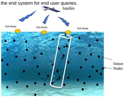
483 are used to link with the satellite. At the end data is forwarding
to the end system for end user queries.
Fig. 1. UWSN architecture
3.2 Problem Description
In UWSNs, the movable nodes results in the non-uniform distribution of nodes in the area. Due to mobility some regions results in the highly dense area, some results in lesser dense region. In highly dense area nodes are enough for data communication. In lesser dense areas nodes are sparse, that result in the void holes in the network area. That is caused of two reasons: either non availability of nodes or due to energy depletion of nodes in that area which causes energy holes. In adaptive hop by hop vector based forwarding the next forwarder node selection procedure is not suitable to select the most appropriate forwarder node. For example in figure 2, Node A is the current source node, its transmission range is the TX-A. It is shown as circular structure. Two parallel lines along the circle restrict the forwarding nodes among these parallel lines structure only. Nodes W, X, Y and Z are nodes having lower depth than current sensor node. Some nodes are simply discarded because these are having higher depth than the sensor node. When A transmits a data packet all neighbour nodes within the transmission range listens to this message including the nodes at higher depth. Higher depth nodes simply discard this packet. Also node Z discards this packet, because node Z is outside the virtual parallel lines region. Only the nodes W, X and Y are qualified to the forwarder node. Also among these nodes, node W and Y are far from the sink node so these will not be selected as the next forwarder node only node X is selected as the best forwarder node. Through this one hop forwarder node selection does not avoid the void hole problem. If node X continue to forward the data this will suffer from void hole problem.
3.3 2-Hop Adaptive Routing Scheme
Energy is the major concern in designing sensor networks. Energy holes an sparse density problem lead to the void hole problem in some regions. The occurrence of void holes causes the unnecessary depletion of energy which results in high delay and shorter lifetime of the network. Recovering from the void holes is very difficult. So rather than to avoid from the void holes, we proposes the scheme to avoid the void holes in the region. Proposed schemes consider four parameters: Balance energy of the node, distance between sensor and receiver node, threshold value for the number of nodes and distance of
selected node to the virtual vector. These parameters are needed to ensure that a best suitable node must be selected, because if we don’t consider these, same nodes may be selected again and again for forwarding data which results in the energy depletion of the nodes. This energy depletion leads to the hole creation. Probability of hole detection and avoidation can be computed as (1-(1-p)2) here p can be calculated by pi*R2/r. r is the radius of the network and R denoted the sensing range of the node.
3.4 Best forwarder node selection
Data forwarding from sensor to sink node is done in done by various ways, such as next hop forwarding selective diversity data forwarding and sensor specific data forwarding [4]. We proposed the data forwarding scheme similar to SDF. In proposed algorithm best forwarder node is selected based four parameters: residual energy of neighbour/forwarder node, distance between sender and forwarder node and for handling the mobility of nodes due to water currents distance between virtual vector and forwarder node and number of prospective neighbour nodes are also taken into consideration. All four parameters can be defined by function in Eq.
S1= REr (1)
Fitness function S1 shows that it is directly proportional to the residual energy of a node (REr). Residual energy of any node will be equal to or less than the E0. E0 is initial energy set to 100 J initially.
S2= 1+sign (N-2) (2)
S2 function is used to select the best forwarder node among all potential neighbours. This forwarder node must be having number of neighbors equal to or greater than threshold value.
S3= Dab (3)
S3 denotes the distance between the sender a and sender b. S3 defines the distance between the sender node to forwarder node. If the Dab is larger than data packets have to travel some hops.
S4=1/(1+dv) (4)
S4 define the distance between the virtual vector and the forwarder node. For reducing the chances of void occurrences, distance between the virtual vector and forwarder node must be small.
Composite function S5 is calculated as described in Eq. (5)
S5 S1S2S3 S4
(5)
By Normalization it can be defined as described in Eq. (6)
0
1 2
(
2 1
a b r
p
m a x
s ig n n D R E
S
d v D E
(6)
484 equation:
B F p p T | 2 | s o u n d
R S F H o ld T S
V (7) 3.5 Terminology
Some of the packet types used in the algorithm has been explained in this section.
Prospective Neighbour node: Initially while network is deployed with in a specific area. Routes between nodes has been computed by exchanging messages. Two type of messages are used named as NQuery (Neighbour Query) and NAck (Neighbour Acknowledgement) messages. NQuery message is sent by sender node to find out the potential neighbour node to be act as best forwarder node. This message packet formed by a tuple which consists of <M_Type, S_id, xs, ys, zs >. Here M_Type is the type of the message packet which is denoted by ―00‖ for NQuery, S_id is the id of the sender node, xs, ys and zs are the coordinates of the sender node. When any node receives this Node Query message, it sends back a neighbour acknowledgement message having one tuple of three fields <M_Type, S_id, xs, ys, zs). Here M_Type is ―01‖, S_id is sender id. xs, ys and zs are the coordinates of the sender node. Third type of packet traverse between sender and receiver is data packet having field <M_type, S_id, D_id, xs, ys, zs, xn, yn, zn, P_id, Pr, Tr>. These fields have following meanings: S_id is id of sender node, D_id is destination node id, xs, ys, and zs are x coordinates, y coordinates and z coordinates of sensor node. xn,yn and zn are the x, y and z coordinates of neighbour node. P_id is the packet id, Pr and Tr are the radius of pipeline and the transmission pipeline of the neighbour node. These messages exchange creates a route between sender and the receiver node. The message exchange procedure repeats if a void region occurs; else same route follows for communication. For minimizing the energy consumption unnecessary control messages are reduced.
4
M
ATHEMATICALF
ORMULATIONOne of the widely used mathematical approaches is Linear programming. This is used to find the optimal solution by maximization and minimization of performance parameters. In this process initially an objective function is formulated which is maximize or minimize with the linear constraints. In further section paper explains how liner programming is used to find the improved network performance.
4.1 Decreasing the Energy Tax (ET)
Energy Tax is the energy consumption in packet transmitting and receiving of data. High energy consumption is inversely proportional to the network performance. Higher the energy consumption degrades the network performance. So as described earlier an objective function is formulated for energy tax minimization. 1 ( ) n T i
M i n i m u m E i
(8)Here ET denotes the Energy Tax, which is calculated for all n number of nodes.
( ) r1
( E )
n
C t i j
i
E i j E D N
(9)EC denotes the energy consumption. Energy is consumed in packet transmission and packet receiving from N number of nodes. Et is the energy consumption in transmission. Er is the energy consumption in packet receiving. Eq.(9) defined the energy used in consumption, here D(ij) and N must be greater than or equal to 0.
Etm a xim u m Pt (Hp Lp) D a t a r a t e
(10)
m a xim u m r ( p p) r
P H L
E
D a ta r a te
(11)
m a xi m u m t
E is defined as the maximum transmission energy. It is calculated by transmitting a packet p at some data rate with
transmission power Pt.
m a xi m u m r
E is defined as the maximum receiving energy. Its value is also depends on the transmission power Pt for packet size p (Hp+Lp) with some d ata rate. Total energy of network will be calculated by multiplying initial energy with the number of nodes.
ET o ta l E0n (12)
Similarly Energy Tax (ET) is the total energy consumed in all the rounds. 1 ( ( ) ) R T C i
E E i
(13)Eq. (13) shows the calculation of Energy tax. Where R is the total number of rounds. For constituting the objective function for Energy Tax minimization, consider Energy consumed in transmission and receiving must be less than the initial energy otherwise network could not send data in first round itself. Along with this energy consumption must be greater than the residual energy of a node. Distance between two communicating nodes must be less than the transmission range. Because a node can be transmit and receive from other node only if it is within the range.
E( ,t r) E0 (14)
( ,t r)
r
E R E (15)
M a x I n i t i a l
j
r a n g e i
D T (16)
M i n I n i t i a l
j
r a n g e i
D T (17)
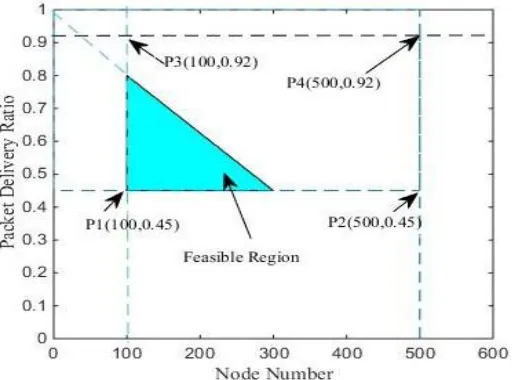
Scenario 1: Assume the transmission range of node is 3000m, it is divided into levels. From L=1 to n. So Packet Size p is Hp+Lp=888 bits, datarate= 16kbps, number of nodes n=500, PT=50W and PR=0.158W respectively. By putting these values Et and Er is calculated as shown in Eq. (18) and (19).
485 1 Et Er 5 .0 0 0 (18)
0 .9 7 7 Et 4 .5 0 5 (19) 0 .1 1 1 Er 0 .9 9 5 (20)
By these Et and Er energy bounds a figure is drawn. Test for each point says:
p1 = 0.977+0.111=1.088 J p2 = 0.977+0.995=1.972 J p3 = 4.505+0.111= 4.616 J p4 = 4.505+0.995= 5.500 J
Fig. 2. Feasible region calculation for Energy Tax Minimization
Through these linear equations it is suggested that feasible region between in the graph tends to decrease the energy consumption.
4.2 Minimization of End-to-End Delay
In network if sender node is in direct range of the sink then source can send data directly to sink. If sink is few hops apart from source node, then source will send data through multiple hops towards sink. In the later scenario delay is calculated for every hop at each level. Delay can be due to one hop when only one hop is in between source to sink; it can be due to multiple hop delay time when multiple hops are in between.
1
4 .1 4 D e l a y h o p D e l a yM H 1 2 .9 (21)
1
1 .8 7 7 D e l a y h o p 3 .8 9 1 (22)
2 .8 8 7 D e l a yM H 7 .8 6 (23)
By checking the each vertex of the graph: p1 = 1.877+2.887=4.764 s
p2 = 1.877+7.86= 9.737 s p3 = 3.891+2.887= 6.778 s p4 = 3.891+7.86= 11.751 s
1
( ) n
t o t a l i
M i n i m u m D e l a y i
(24)D e la y D e la y(T)D e la y(p r o) H o ld(B F) (25)
p
( )
( H )
a b p
B F
s o u n d
D L
D e l a y H o l d V d a t a r a t e
(26)
Fig. 3. Feasible region calculation for End-to-End delay
4.3MAXIMIZATION OF THROUGHPUT
Throughput is defined as the total number of packets received at the sink successfully. To maximize the throughput regular quality check is to be done. Transmission energy used in transmitting the data packet should be less than the residual energy of the sender node. Distance between the sender and receiver node must be greater than minimum distance Dmin and should be less than the maximum distance. By considering all these factors objective function is defined as:
1
( ) n
h p
i
M i n i m u m T i
(27)Case 1: Et r, R Er
Case 2: Et r, ET h r
Case 3: 0 a b m a xi m u m a b
D D
5
R
ESULT ANDD
ISCUSSION486
Fig. 4. Feasible region calculation for Throughput
Table1 Parameters initialization
5.1 Metrics for performance evaluation
As discussed in earlier section also three parameters are taken into account to evaluate the performance named Energy Tax, End-to-End delay and Throughput. Energy Tax is defined as the total energy consumed in transmitting and receiving the packets and control message packets in successfully delivering data at the sink node. It could be calculate by the Eq. 28.
Energy_Tax= EC
n p
(28)
Ec is the total energy consumption. N is the total number of nodes deployed in the network. Energy_Tax is calculated in joules. PDR is packet delivery ratio. It is the ratio of the total number of data packets received successfully to the total number of packets sent over network. End-to-End delay is the average delay calculated in transmitting packets and received successfully at the receiver end. It calculates by considering the transmission delay, propagation delay, receiver delay, holding time. It is measured in seconds.
5.2 Energy Tax
Energy decreases with the increase in number of nodes. As the number of nodes increase successful data transfer increases. On the other hand in sparse density when number of nodes is less, packet drop occurs in unavailability of nodes. This leads to increase in energy consumption. [3] takes more energy when number of nodes are less. In this next hop information is not considered. So it can leads packet transmission towards to the void regions. When nodes reach to 300, algorithm [2] outperformers [3]. Proposed algorithm outperforms all algorithms because it selects the best forwarder node which does not lead it to void reason and duplicate packets also decrease because of pipeline method.
Fig. 5. Energy Consumption Comparison
5.3 PDR
Packet delivery ratio is ratio of total number of nodes successfully received to the total number of nodes. PDR increases in dense areas. Reason being when number of nodes increases potential neighbour nodes are increases. PDR ratio is increases up to a threshold then it gets decrease because of sparse areas. Proposed algorithm outperforms [18] because of best node forwarder scheme. After threshold optimal forwarder node is selected by [14] and proposed algorithm so these algorithms performed better than [18]. Proposed algorithm performs 6 % better than [18], also [23] and [14] are slightly better than [18].
Parameters Value
Nodes 500
Sink node 1
E0(Initial Energy) 100 J Node Mobility 1-3 m/s
Network Area 1 0km1 0km1 0km, 3D
Transmission Range 3000 m
Bandwidth 4 kHz
Data rate 16 kbps
Packet size 154 bytes
Mobility model Random walk model Pt(Max transmission
power)
90 dB
Pr (Max receiving power)
487
Fig. 6. Packet Delivery Ratio Comparison
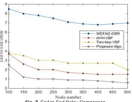
5.4 End to End Delay
End to End delay decreases with increase in the number of nodes. As the number of nodes increase nodes become dense in area. So successful delivery of packets increase because of availability of more number of nodes. Propagation delay increase for deciding the 2 hops in 2hop-AHH-VBF algorithm.
Fig. 7. End to End Delay Comparison
In proposed algorithm best forwarder node is selected by composite function. This also reduces the propagation delay because it avoids the void holes. It performs 35% better in terms of end to end delay than [18]. Up to node 350 [14] [18] follows the same trend after than proposed algorithm outperforms all algorithms.
6. Conclusion
To improve the performance of data transmission in under water sensor networks, multiple hop data forwarding scheme is proposed in this paper. This algorithm avoids the void regions by considering various parameters in selecting the best forwarder nodes. This considers residuals energy of sender and receiver nodes, distance between sender and receiver, number of neighbours nodes and distance between neighbour and the virtual vector. These parameters avoids void regions along with this it picks the best forwarder node for
data transfer, which increase the PDR. Also proposed algorithm beats other algorithm in terms of energy consumption too. Energy consumption decreases because PDR increases with the number of nodes at the cost of lesser end to end delay. Proposed algorithm outperforms [14] [18] and [23], even in sparse networks.
R
EFERENCES[1] Azam, I.; Javaid, N.; Ahmad, A.;Wadood, A.; Almogren, A.; Alamri, A. Balanced Load Distribution with Energy Hole Avoidance in Underwater WSNs. IEEE Access 2017, doi:10.1109/ACCESS.2017.2660767.
[2] Javaid, N.; Shah, M.; Ahmad, A.; Imran, M.; Khan, M.I.; Vasilakos, A.V. An Enhanced Energy Balanced Data Transmission Protocol for Underwater Acoustic Sensor Networks. Sensors 2016, 16, 487, doi:10.3390/s16040487. [3] Akbar, M.; Javaid, N.; Khan, A.H.; Imran, M.; Shoaib, M.;
Vasilakos, A. Efficient data gathering in 3D linear underwater wireless sensor networks using sink mobility. Sensors 2016, 16, doi:10.3390/s16030404.
[4] Larsson, P. Selection diversity forwarding in a multihop packet radio network with fading channel and capture. ACM SIGMOBILE Mob. Comput. Commun. Rev. 2001, 5, 47–54. [5] Clausen, T.; Jacquet, P. Optimized Link State Routing Protocol
(OLSR). 2003. Available online: http://www.rfc-editor.org/info/rfc3626 (accessed on 28 July 2017).
[6] Perkins, C.E.; Bhagwat, P. Highly dynamic destination-sequenced distance-vector routing (DSDV) for mobile computers. In ACM SIGCOMM Computer Communication Review; ACM: New York, NY, USA, 1994; pp. 234–244. [7] Royer, E.M.; Perkins, C.E. Multicast operation of the ad-hoc
on-demand distance vector routing protocol. In Proceedings of the 5th Annual ACM/IEEE International Conference on Mobile Computing and Networking, Seattle,WA, USA, 15–19 August 1999; ACM: New York, NY, USA, 1999; pp. 207–218.
[8] Johnson, D.B.; Maltz, D.A. Dynamic source routing in ad hoc wireless networks. In Mobile Computing; Springer: New York, NY, USA, 1996; pp. 153–181. Sensors 2017.
[9] Ayaz, M.; Abdulla, A. Hop-by-hop dynamic addressing based (H2-DAB) routing protocol for underwater wireless sensor networks. In Proceedings of the International Conference on Information and Multimedia Technology, Jeju Island, Korea, 16–18 December 2009; pp. 436–441.
[10]Domingo, M.C. A distributed energy-aware routing protocol for underwater wireless sensor networks. Wirel. Pers. Commun. 2011, 57, 607–627.
[11]Liu, G.;Wei, C. A new multi-path routing protocol based on cluster for underwater acoustic sensor networks. In Proceedings of the 2011 International Conference on Multimedia Technology (ICMT), Hangzhou, China, 26–28 July 2011; pp. 91–94.
[12]Yan, H.; Shi, Z.J.; Cui, J.-H. DBR: Depth-based routing for underwater sensor networks. In Proceedings of the International Conference on Research in Networking, Singapore, 5–9 May 2008; Springer: Berlin/Heidelberg, Germany, 2008; pp. 72–86.
[13]Wahid, A.; Kim, D. An energy efficient localization-free routing protocol for underwater wireless sensor networks. Int. J. Distrib. Sens. Netw. 2012, 8, doi:10.1155/2012/307246. [14]Yu, H.; Yao, N.; Wang, T.; Li, G.; Gao, Z.; Tan, G.
488 [15]Majid, A.; Azam, I.; Khan, T.; Khan, Z.A.; Qasim, U.; Javaid, N.
A reliable and interference-aware routing protocol for underwater wireless sensor networks. In Proceedings of the 2016 10th International Conference on Complex, Intelligent, and Software Intensive Systems (CISIS), Fukuoka, Japan, 6–8 July 2016; pp. 246–255.
[16]Xie, P.; Cui, J.-H.; Lao, L. VBF: Vector-based forwarding protocol for underwater sensor networks. In Proceedings of the International Conference on Research in Networking, Coimbra, Portugal, 15–19 May 2006; Springer: Berlin/Heidelberg, Germany, 2006; pp. 1216–1221.
[17]Xie, P.; Zhou, Z.; Nicolaou, N.; See, A.; Cui, J.-H.; Shi, Z. Efficient vector-based forwarding for underwater sensor networks. EURASIP J. Wirel. Commun. Netw. 2010, 2010, doi:10.1155/2010/195910.
[18]Yu, H.; Yao, N.; Liu, J. An adaptive routing protocol in underwater sparse acoustic sensor networks. Ad Hoc Netw. 2015, 34 121–143.
[19]Sudevalayam, S.; Kulkarni, P. Energy harvesting sensor nodes: Survey and implications. IEEE Commun. Surv. Tutor. 2011, 13, 443–461.
[20]Knight, C.; Davidson, J.; Behrens, S. Energy options for wireless sensor nodes. Sensors 2008, 8, 8037–8066.
[21]Syed, A.A.; Ye, W.; Heidemann, J.; Krishnamachari, B. Understanding spatio-temporal uncertainty in medium access with ALOHA protocols. In Proceedings of the Second Workshop on Underwater Networks, Montreal, QC, Canada, 14 September 2007; ACM: New York, NY, USA, 2007; pp. 41–48.
[22]Peng, Z.; Zhu, Y.; Zhou, Z.; Guo, Z.; Cui, J.H. COPE-MAC: A contention-based medium access control protocol with parallel reservation for underwater acoustic networks. In Proceedings of the OCEANS 2010 IEEE Sydney, Sydney, Australia, 24–27 May 2010; pp. 1–10.
[23]Nadeem Javaid et. al., ―Two Hop Adaptive Vector Based Quality Forwarding for Void Hole Avoidance in Underwater WSNs‖, Sensors 2017, 17, 1762; doi:10.3390/s17081762, pp 1-21.
[24]G. Khan, R. K. Dwivedi, et. al., ―Comparative Analysis of Routing Algorithms for Underwater Sensor Network‖, Book Chapter in Pervasive Computing: A Networking Perspective and Future Directions, pp. 31-46, 2019.
[25]G. Khan, R.K. Dwivedi, ―Energy Efficient Routing Algorithm for Void Avoidance in UWSN Using Residual Energy and Depth Variance‖, International Journal of Computer Networks & Communications (IJCNC), Vol 10, No. 4, 2018.
[26]G. Khan, Bathla G. et. al., ―Minimum Spanning Tree based Routing Strategy for Homogeneous WSN‖, International Journal on Cloud Computing: Services and Architecture ( IJCCSA),Vol.1, No.2, August 2011.