1
Modelling and Simulation of Vehicle Windshield Wiper
System using H
Loop Shaping and Robust Pole Placement
Controllers
Mustefa Jibril1, Messay Tadese2, Eliyas Alemayehu Tadese3
1 Msc, School of Electrical & Computer Engineering, Dire Dawa Institute of Technology, Dire Dawa,
Ethiopia
2 Msc, School of Electrical & Computer Engineering, Dire Dawa Institute of Technology, Dire Dawa,
Ethiopia
3 Msc, Faculty of Electrical & Computer Engineering, Jimma Institute of Technology, Jimma, Ethiopia
Abstract
Vehicle windshield wiper system increases the driving safety by contributing a clear shot viewing to the driver. In this paper, modelling, designing and simulation of a vehicle windshield wiper system with robust control theory is done successfully. H loop shaping and robust pole placement controllers are used to improve the wiping speed by tracking a reference speed signals. The reference speed signals used in this paper are step and sine wave signals. Comparison of the H loop shaping and robust pole placement controllers based on the two reference signals is done and convincing results have been obtained. Finally the comparative results prove the effectiveness of the proposed H Loop Shaping controller to improve the wiping mechanism for the given two reference signals.
Keywords: H Loop Shaping, Robust Pole Placement, Windshield 1. Introduction
Driving a vehicle is complicated in harsh weather condition without using glass wiper system. Controlling the wiper speed based on the change in weather condition is one of the research area in automotive industries now a day. Recently, the wiper speed is adjusted manually controlled by the driver. Dc motors are used to drive the wiper system based on feed forward techniques. In this paper a separately excited Dc motor is designed and controlled using robust control method to improve the feed forward wiper system performance.
2. Mathematical Modelling
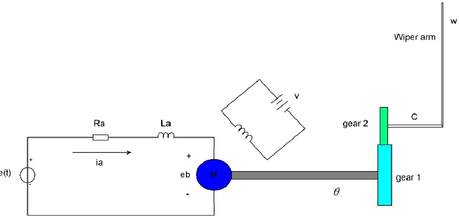
Consider the electromechanical car mirror wiper system shown in Figure 1.
2
Figure 1 Electromechanical car mirror wiper system
The motor shown is a servomotor, a dc motor designed in particular for use in a control system. The operation of this device is as follows: A fixed voltage is carried out to the field winding. A voltage is implemented as an input to the servo motor and the angular position c of the wiper arm is the output of the device. The input voltage is implemented to the armature circuit of the dc motor. A constant voltage is carried out to the field winding. If an errors exists, the motor develops a torque to rotate the output load in the sort of way as to reduce the error to zero. For constant field current, the torque evolved by using the motor is
1a 1
T K i
Where K1 is the motor torque constant and ia is the armature current.
When the armature is rotating, a voltage proportional to the fabricated from the flux and angular velocity is brought on within the armature. For a constant flux, the brought about voltage eb is
without delay proportional to the angular velocity d
dt
or
2 2
b
d
e K
dt
Where eb is the back emf, K2 is the back emf constant of the motor, and is the angular displacement of the motor shaft.
The speed of an armature-managed dc servomotor is managed via the armature voltage e(t). The differential equation for the armature circuit is
3
a
a a a b
di t
L R i t e e t
3 Substituting Equation (2) in to Equation (3) yields:
2 4
a
a a a
di t d
L R i t K e t
dt dt
Taking the Laplace transform the equation will be
2
5 a a a asL I s R I s sK s E s
The equation for torque equilibrium is
2
0 2 0 1a 6
d d
J b T K i t
dt dt
Taking the Laplace transform the equation will be
2
0 0 1 a 7
s J s b s K I s
Where J0 is the inertia of the combination of the motor, load, and gear train referred to the motor shaft and b0 is the viscous-friction coefficient of the aggregate of the motor, load, and gear train mentioned the motor shaft.
By eliminating I sa
from Equations (5) and (7), we obtain
3 2
1
0 0 0 2 0
8
a a a a
s K
E s L J s J R s L b K s b R
We assume that the gear ratio of the gear train is such that the output shaft rotates n times for each revolution of the motor shaft. Thus,
9C s n s
The wiper arm speed can be evaluated by using an integrator to the wiper arm position as
1
10
W s C s
s
Substituting Equation (10) in to Equations (9) and to Equations (8) gives us the transfer function between the applied voltage and the wiper speed as
4 3
1
2
0 0 0 2 0
11
a a a a
W s nK
E s L J s J R s L b K s b R s
4
Table 2 Parameters of the system
No Parameters Symbol Values
1 Inertia of the motor, load, and gear train
0
J
2 210
Kg m
2 Viscous-friction coefficient
0
b
0.2N ms rad/3 Back emf constant
2
K
0.8V s rad/4 Motor torque constant
1
K
0.7N m amp/5 Motor Resistance
a
R
1.26 Motor Inductance
a
L
23 10
H
7 Gear ratio n 25
Numerically the transfer function is
4 3 217500
3 12 806 240 G s
s s s s
The state space form will be
40 2686.7 800 0 1
1 0 0 0 0
0 1 0 0 0
0 0 1 0 0
0 0 0 58333
x x u
y
3. Proposed Controllers Design
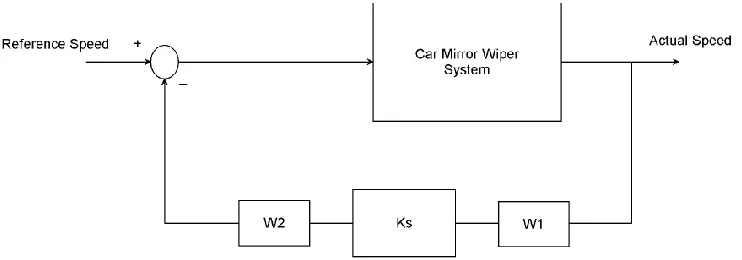
3.1H infinity Loop shaping using Glover-McFarlane method Controller Design The block diagram of the car mirror wiper system with H infinity Loop shaping design using
5
Figure 2 car mirror wiper system with H infinity Loop shaping design using Glover-McFarlane method
A feedback controller, KS, is synthesized that robustly stabilizes the normalized left cop rime factorization of G, with a balance margin. It may be proven that the frequency response of KsW2GW1 will be much like that of W2GW1. On the other hand, if the viable gain is simply too
large, this will probable indicate an overdesigned case in appreciate of the robustness, which means that the performance of the system can also in all likelihood be progressed by the usage of
a larger in computing Ks. The final feedback controller, Kfinal, is then constructed with the aid of combining the H infinity controller Ks, with the weighting functions W1 and W2 such that
1 2 12
final s
K W K W
We choose a precompensator, W1, and a postcompensator, W2 transfer functions as
1 2
1 1
24 13
W W
s s
The H infinity controller transfer function is
5 4 3 2
7 6 5 4 3 2
1.419 109.3 6357 1.6 05 1.235 06 3.84 05
114.3 7678 3.05 05 6.536 06 6.968 07 3.027 08 1.7 08
s
s s s e s e s e
s s s e s e s
K
e s e s e
3.2Robust Pole Placement Controller Design
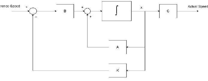
In a typical feedback manage system, the output, y, is fed back to the summing junction. It is now that the topology of the layout changes. Instead of feeding again y, what if we feed back all of the state variables? If each state variable is fed back to the manipulated, u, through a gain, ki, there might be n gains, ki that would be adjusted to yield the required closed-loop pole values. The feedback via the profits, ki, is represented by way of the feedback vector -K.
The block diagram of the car mirror wiper system with robust pole placement method is shown in Figure 3.
Figure 3 car mirror wiper system with robust pole placement method
6
13x Ax Bu Ax B Kx A BK x
y Cx
The poles for this system is chosen as
P = 1 2 , 1 2 , 4 3 , 4 3i i i i
Solving using Matlab the robust pole placement algorithm gain will be
46 26727 790 125
K
4. Result and Discussion
In this section, the Simulink model design and simulation of the vehicle windshield wiper system using H infinity loop shaping and robust pole placement controllers by comparing the two proposed controllers for tracking the step and sine wave speed references.
4.1Comparison of the proposed controllers for tracking the step speed reference
The Simulink model of the vehicle windshield wiper system using H infinity loop shaping and robust pole placement controllers for tracking the step speed reference is shown in Figure 4 below.
Figure 4 Simulink model of the vehicle windshield wiper system using H infinity Loop Shaping and Robust Pole Placement Controllers for tracking the step speed reference
7
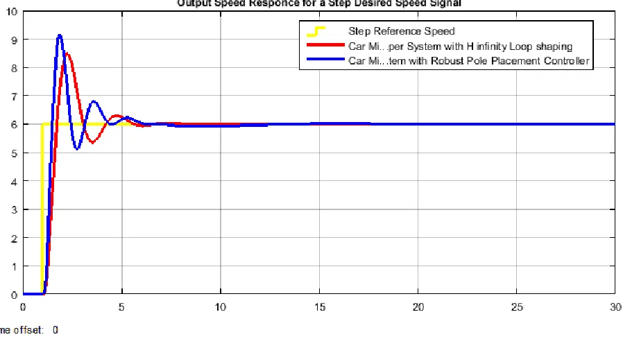
Figure 5 Simulation result for a step reference input
The data of the rise time, percentage overshoot, settling time and peak value is shown in Table 1.
Table 1 Step response data
No Performance Data Robust Pole Placement H infinity Loop Shaping
1 Rise time 1.2 sec 1.22 sec
2 Per. overshoot 53.4 % 40 %
3 Settling time 8 sec 6 sec
4 Peak value 9.2 m 8.4m
8
Figure 6 Simulink model of the vehicle windshield wiper system using H infinity loop shaping and robust pole placement controllers for tracking the sine speed reference
The wiper system performance for the proposed controllers using a sine wave reference (wiper moving in the forward and reverse with 6 m/s) of the wiper speed simulation is shown in Figure 7 below.
9
The simulation result shows that the vehicle windshield wiper system with H infinity loop shaping controller track the reference speed better than the vehicle windshield wiper system with robust pole placement controller.
5. Conclusion
The vehicle windshield wiper system is designed and simulated based on the given control signals using Matlab/Simulink and a promising result have been analyzed. The performance of the vehicle windshield wiper system is tested for wiping speed regulation using track a signal method. Comparison of the vehicle windshield wiper system with H infinity loop shaping and robust pole placement controllers is done for a step and sine wave reference speed signals and the vehicle windshield wiper system with H infinity loop shaping controller shows a good result in improving the wiping mechanism in almost the all performance measures taken. Finally the comparative results prove the effectiveness of the proposed H Loop Shaping controller to improve the wiping mechanism for the given two reference signals.
Reference
[1].Vijay S. et al. “Automatic Rain Operated Wiper and Headlight Dim and Bright Controller” International Journal of Innovative Research in Science, Engineering and Technology, Vol. 9, Issue 2, February 2020.
[2].Punam W. et al. “An Automated Wiper System for Vehicles” International Journal for Research in Applied Science & Engineering Technology (IJRASET), Volume 7 Issue IV, Apr 2019.
[3].Matthew B. et al. “Windshield Wipers on Connected Vehicles Produce High Accuracy Rainfall Maps” Journal of Scientific Reports, Vol. 9, 2019.
[4].Varshitha P J et al. “Improvement of Auto Wiper Controller According to Rain Force” International Journal of Advanced Research in Electrical, Electronics and Instrumentation Engineering, Vol. 7, Issue 5, May 2018.
[5].Prajakta C. et al. “Automatic Rain Operated Wiper and Dimmer for Vehicle” International Research Journal of Engineering and Technology (IRJET), Volume: 03 Issue: 04, 2016. [6].Lubna A. et al.”Design and Implementation of a Reconfigurable Automatic Rain Sensitive
Windshield Wiper” International Journal of Engineering & Technology Science, Vol. 8, Issue 2, pp. 73-82, 2015.
[7].Mark D. et al. “Dynamic Modelling and Experimental Validation of an Automotive Windshield Wiper System for Hardware in the Loop Simulation” Journal of Systems Science & Control Engineering, Vol. 3, Issue 1, 2015.