R E S E A R C H
Open Access
A distributed algorithm using interference
pricing for relay interference channels
Kien T Truong and Robert W Heath, Jr
*Abstract
Relays in cellular systems are sensitive to interference. A good relay design will transmit in a way that avoids excess out-of-cell interference. This article proposes a two-step algorithm for relay design for the relay interference channel, which models a relay-based cellular system. The transmitters and relays are equipped with multiple antennas while the receivers are equipped with a single antenna. In the first step, we propose to apply existing single-hop strategies to design the transmission parameters of the transmitters. In the second step, we propose to modify the interference pricing approach to design the relays. Interference pricing is used to provide the relays with information on how interference impacts the end-to-end achievable rates. A new method is proposed to compute interference prices via an approximation of the end-to-end achievable rate to integrate information about the relationship of the parameters in the two hops to alleviate mismatch between the rates on two hops experienced by the direct application of prior algorithms, which are designed specifically for the single-hop interference channel. Simulations show that the proposed algorithm outperforms the other designs, including the naive approach of applying the single-hop interference pricing strategies on two hops.
Introduction
The relay interference channel models multiple transmitter–receiver pairs communicating through ded-icated relays using the same spectral resource [1-4], as in cellular systems with relays. On the first hop, the transmitters send data to the relays; on the second hop, after some signal processing, the relays forward data to the receivers. Each hop experiences interference, causing resource conflicts, and coupling the achievable rates for the two-hop links. In addition, the end-to-end achievable rate of a two-hop link is limited by rates achieved on each hop. Achieving high end-to-end sum-rates, therefore, requires strategies that not only mitigate interference [4,5] but also match the rates on the two hops of the relay-aided links. Unfortunately, configuring the relays with limited information about the interference is chal-lenging. Prior work on relay design for cellular systems often neglects interference [6] or ignores matching the rates in the two hops [7-9].
In this article, we maximize the end-to-end sum-rates from the base stations (i.e., the transmitters) to
*Correspondence: [email protected]
Department of Electrical and Computer Engineering, The University of Texas at Austin, 1 University Station, C0806, Austin, TX 78712-0240, USA
the mobile stations (i.e., the receivers) through a set of fixed relays. We assume that the transmitters send data to the receivers with the aid of fixed, half-duplex, and decode-and-forward (DF) relays via two-hop transmis-sions. The transmitters and relays do not share data. While the transmitters and the relays are equipped with multiple antennas, the receivers have a single antenna. The direct channels from the transmitters to the receivers are neglected due to high path-loss and shadowing attenuation. We assume that the two-hop links have a common timesharing value and perfect inter-user frame synchronization, i.e., the transmissions in each hop start at the same time and end at the same time. Although this assumption requires some coordination among the trans-mitters before the actual data transmission, it allows for tractable analysis to obtain insights into the system perfor-mance and provides a benchmark for the scenarios with relaxed assumptions on inter-user frame synchronization. We also assume that the parameters of the first hop are fixed and focus on the design of transmission param-eters at the relays. This is reasonable when the relays are allowed to schedule users [10], as in IEEE 802.16j [11], IEEE 802.16m [12], and 3GPP LTE/LTE-Advanced standards [13]. It is important to note that we consider
end-to-end achievable rates. Thus, the design challenge is how to take into account information about the fixed first-hop parameters and the timesharing value in the con-figuration of the second hop while mitigating interference. Our design problem is to determine transmit precoders at the transmitters and relays to maximize the end-to-end sum-rates. The single-hop sum-rate maximization problem is non-convex and NP-hard, i.e., its globally optimal solution cannot be found efficiently in terms of computational complexity [14]. More complicated, the joint transmit precoder problem for end-to-end sum-rate maximization is also non-convex and is expected to be NP-hard. This motivates us to develop an algorithm for transmit precoder design that obtains high end-to-end sum-rates, i.e., to find efficiently suboptimal solutions to the end-to-end sum-rate maximization problem. Note that prior work often focuses on single-hop sum-rate maximization. Then existing algorithms could be applied to maximize independently the sum-rates in each hop of the two-hop interference channel. This naive approach, however, leads to rate mismatch in the two hops, which reduces the end-to-end sum-rates. Rate mismatch occurs when some relay links have a dominant first hop while others have a dominant second hop. From a resource allocation perspective, this means it wastes resources to the second-hop dominant relay links while depriving resources from the first-hop dominant relay links.
In this article, we propose a two-step algorithm for designing the transmit precoders at the transmitters and relays. In the first step, we propose to apply directly the existing single-hop strategies for the first hop to design the precoders at the transmitters. The relays then esti-mate their received signal-to-interference plus noise ratio (SINR), which represent the achievable rates on the first hop. In the second step, we use interference pricing [15-17] to develop a distributed relay beamforming algo-rithm where each relay determines its own transmit pre-coder without explicit knowledge of the prepre-coders at the other relays and of the channels from the other relays. We propose a new method for computing interference prices at the receivers such that interference prices also include information about the first-hop SINR and the timeshar-ing value. Our approach uses an approximation function of the end-to-end achievable rate to take into account the relationship of the parameters on two hops. We describe how the new two-hop interference pricing framework is used to develop an asynchronous-distributed pricing algorithm for relay transmit beamforming. In each itera-tion of the algorithm, one randomly selected relay updates its own precoder based on the knowledge of interference prices corresponding to unintended receivers by solving a nonlinear optimization problem. In general, however, finding the globally optimal solutions to this nonlin-ear optimization problem may be time-consuming. To
overcome this challenge, we propose a method for solving it approximately, although we are unable to prove ana-lytically the convergence of the modified algorithm. We also present in detail a version of the proposed algorithm, which we refer to as the two-hop interference pricing algorithm for relay transmit power control, where we can find closed-form expressions for the updates at the relays. This power control algorithm is applicable when the relays have a single antenna. It is also applicable when the relays have multiple antennas but we focus on designing only the norm of the relay precoders. The end-to-end sum-rate performance of the proposed algorithm is evaluated by Monte Carlo simulations in a multicell cellular net-work. We observe that the modified algorithm converges in the simulated scenarios. For comparison, we implement a number of relay transmission strategies, including the naive application of the single-hop interference pricing algorithm in [16] to the second hop. The numerical results show that, thanks to the capabilities of interference mit-igation and two-hop rate-mismatch alleviation, the pro-posed algorithm always outperforms all other algorithms for various system configurations.
[12] while 3GPP LTE/LTE-Advanced considered both DF and amplify-and-forward relays [13].
Power control is a classic technique for interfer-ence mitigation in cellular systems (see [34] and ref-erences therein). For example, there are several game theory-based power control algorithms for the single-hop interference channel [15,35-43] and femtocell networks [44,45]. While Huang et al. [15] uses interference pric-ing, Stanczak et al. [40,43] use the framework of adjoint networks that allow for fully distributed implementation. Similar to the case of beamforming, since the prior algo-rithms are developed specifically for the single-hop inter-ference channel, their direct applications for the second hop cause rate mismatch. The literature on power control algorithms for relay-assisted wireless networks, however, is limited [4,46-48]. An algorithm for power control at the relays and transmitters in interference relay channel is developed in [46], but it aims at minimizing the total transmit power subject to SINR requirements. The prior work in [4,47] determines allocation of the sum power for each two-hop link for its transmitter and relay in a two-user two-hop interference channel to maximize the end-to-end sum-rates. Not only is the problem formu-lation in [4,47] different from ours, but also the results cannot be easily extended to the case with more than two users. An algorithm for power control at both the base stations and relays in a multi-cell network is developed in [48]. The idea is based on the use of pricing factors to reflect the impact of interference, which is in principle similar to that of interference pricing. Nevertheless, pric-ing factors in [48] are determined numerically rather than by analytical methods. Also, it is unclear how the pricing factors can be extended for the beamforming design.
Our initial results in this article were reported in [49]. Compared with [49], this article presents in more detail the proposed two-hop interference pricing, discusses the distributed two-hop interference pricing algorithm, and provides more simulations that emphasize the achiev-able end-to-end sum-rate performance of the proposed algorithm in comparison with the existing strategies. In addition, we reported some related results on the DF relay broadcast interference channel reported in [50]. Although it also aims at the alleviating two-hop rate-mismatch while mitigating interference, our prior work in [50] adopts another approach, which is based on a rela-tionship between mean squared error (MSE) values and mutual information. Comparing the two approaches, the idea in [50] has higher channel state information (CSI) requirements and is more complex, but has the advantage of supporting multi-user multiple-input multiple-output (MIMO) from the relays.
The organization of this article is as follows. First, we introduce the system model of the relay interference channel. Second, we formulate the problem of sum
end-to-end achievable rate maximization and discusses the challenges in finding its optimal solutions. Third, we present in detail the proposed approach that is based on the interference pricing framework to find high-quality suboptimal solutions. Fourth, we present Monte Carlo simulations with a multi-cell system setting. Finally, we conclude this article and provide suggestions for future research.
Notation. The lowercase and uppercase boldface let-ters (e.g.,handH) indicate column vectors and matrices, respectively. h∗ and h denote the complex conjugate transpose and theL-2 norm ofh.IN stands for the iden-tity matrix of sizeN×N. We useνmax(H)to denote the eigenvector corresponding to the maximum eigenvalue ofH.|a| denotes the absolute value of a complex scalar numbera. The subscript(){1}implies the first stage while (){2} for the second stage. The superscript ()(n) denotes thenth iteration.E[·] is the statistical expectation opera-tor. For any stacked notationX= (x1,. . .,xK), we define X−k (x1,. . .,xk−1,xk+1,. . .,xK)fork∈ {1,. . .,K}. We useXand(xk;X−k)interchangeably.
System model
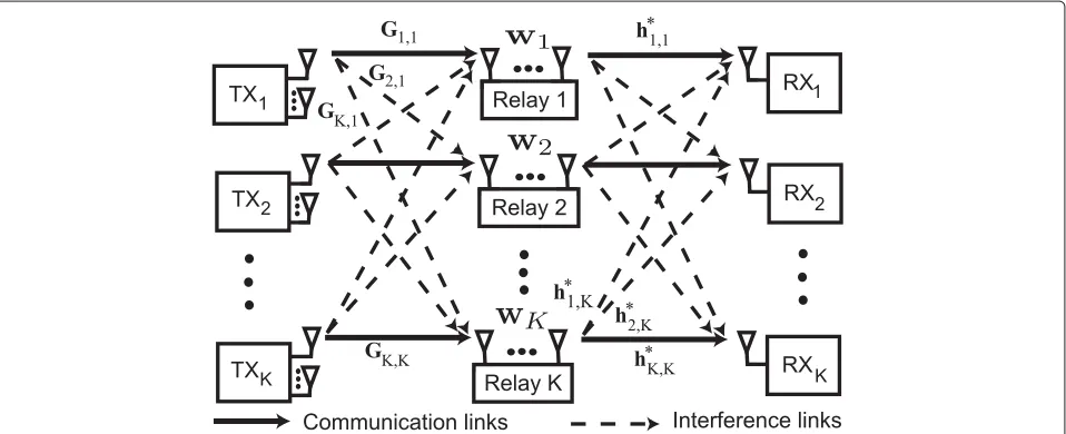
Consider aK-user relay interference channel withKpairs of transmitters and receivers, as illustrated in Figure 1. We assume that the direct channels from the transmit-ters to the receivers are neglected due to high path-loss and shadowing attenuation. This is quite reasonable as it simply requires that the receivers in the second step not try to listen to the first hop transmission. For example, this happens in the downlink of a cellular net-work when the mobile stations are located near the cell boundary. One half-duplex DF relay is dedicated to each transmitter–receiver pair. A unique indexk from the set K {1,. . .,K} is assigned to each pair and its associ-ated relay. We assume that each relay does not attempt to decode the signals of the other transmitters than its assigned one. The transmitters and relays do not share data. We assume that transmitterkhasMkantennas and relaykhasNkantennas, whereMk,Nk ≥1 fork∈K. We assume each receiver is equipped with a single antenna and focus on only the design of the relays.
Figure 1TheK-user two-hop interference channel.The transmitters (TXs) and the half-duplex DF relays are equipped with multiple antennas while the receivers (RXs) have a single antenna. Each relay aids the signal forwarding of only one TX–RX pair. The transmission procedure requires two stages. In the first stage, the TXs send data to the relays. In the second stage, each relay decodes its received signal, re-encodes and retransmits to its associated RX.
synchronization assumption is made either explicitly or implicitly in much prior work on interference channel. Moreover, this assumption allows for tractable analysis to obtain insights into the system performance and pro-vides a benchmark for the scenarios with relaxed assump-tions on inter-user frame synchronization. Using common radio resources, the transmissions in the same stage inter-fere with each other. For tractable analysis, we assume Gaussian signaling in both stages although it may not be optimal for the relay interference channel. In the first stage, the transmitters send data to their relays. Treat-ing interference signals as additive Gaussian noise, each relay decodes the desired signal, re-encodes and retrans-mits to its receiver in the second stage. Each receiver also treats the interference from unintended relays as additive Gaussian noise when decoding the desired signal from its relay.
We consider slowly-varying, frequency-flat block-fading channels. Let 1 ≤ mk ≤ min{Mk,Nk} be the number of data streams that transmitterksends to relayk. Transmitterkuses a fixed linear precoderFT,k ∈CMk×mk to map the symbol vector xk ∈ Cmk×1 to its transmit antennas. The transmitted symbols are i.i.d. such that
E(xkx∗k)=Imk. LetpT,kbe the actual transmit power and
pmaxT,k be the maximum transmit power at transmitter k. The transmit power constraint at transmitterkfork∈K is
FT,k2F =pT,k∈PT,k[ 0,pmaxT,k] . (1)
We denote Gk,q ∈ CNq×Mk as the channel from trans-mitterqto relaykforq,k ∈ K. LetnX,k ∈CNk×1denote
Gaussian noise at relay k withE(nX,kn∗X,k) = σX,2kINX,k. We define FT (FT,1,. . .,FT,K) ∈ FT CM1×m1×
· · · ×CMK×mK andp
T (pT,1,. . .,pT,K) ∈ PT PT,1×
· · · ×PT,K. Relaykobserves
yX,k =Gk,kFT,kxk+
q=k
Gk,qFT,qxq+nX,k. (2)
The interference plus noise covariance matrix at relaykis
RX,k(FT)=
q=k
Gk,qFT,qF∗T,qGk∗,q+σX,2kINX,k. (3)
The maximum achievable rate from transmitterkto relay kis
R1,k(FT)=log2det
IN+F∗T,kG∗k,k[RX,k(FT)]−1Gk,kFT,k
. (4)
Define ξk(FT) = 2R1,k(FT) −1. Intuitively, one can think ofξk(FT) as an effective SINR at relayk if transmitterk sends a single data stream to relayk.
Since relay k is dedicated to aiding the kth pair by assumption, it attempts to decode onlyxk. After that, relay kre-encodes the signal asrksuch thatE(|rk|2)=1. Relay kuses a linear beamforming vectorfX,k ∈CNk×1to trans-mitrkto receiverk. LetpX,kbe the actual transmit power andpmaxX,k be the maximum transmit power at relayk. The transmit power constraint at relaykfork∈Kis
fX,k2F =pX,k ∈PX,k [ 0,pmaxX,k ] . (5)
We defineFX (fX,1,. . .,fX,K) ∈ FX CN1×1× · · · × CNK×1 and P
Leth∗k,m denote the channel from relay mto receiver k, wherehk,m ∈ CNk×1. We denotenR,kas the additive spa-tially white Gaussian noise at receiverk fork ∈ Kwith varianceσR,2k. Receiverkobserves
yk=h∗k,kfX,krk+
q=k
h∗k,qfX,qrq+nR,k. (6)
Define the signal power as Ak(FX) f∗X,khk,kh∗k,kfX,k and the sum interference power as Ik(FX)q=kf∗X,q hk,qh∗k,qfX,q. The SINR at receiverkis
γk(FX)=
Ak(FX)
Ik(FX)+σR,2k
. (7)
The maximum achievable rate of thekth second-hop link is given by
R2,k(γk(FX))=log2(1+γk(FX)). (8)
Lett ∈ (0, 1) be the fraction of time allocated for the first stage, which is also referred to as the timesharing value. The fraction of time for the second stage is(1−t). For example, in 3GPP LTE/LTE-Advanced cellular sys-tems,tdepends on the number of subframes for backhaul links (i.e., between base stations and relays) in a radio frame [13]. We assume thattis a given parameter. Find-ing the optimal value fortis an interesting problem but it increases the requirements for synchronization and coor-dination among the two-hop links. The normalized rate of thekth first-hop link istR1,k(FT)while the normalized rate of thekth second-hop link is(1−t)R2,k(FX). The end-to-end achievable rate of the link from transmitterkvia relay kto receiverkis defined as the smaller of the normalized rates on two hops [51]
Rk(FT,FX)=min
tR1,k(FT),(1−t)R2,k(FX)
. (9)
The end-to-end sum-rates is defined as
Rsum(FT,FX) K
k=1
Rk(FT,FX). (10)
The design of FT and FX for maximizing Rsum(FT,FX) should take into accountt. Also, note that the units for the achievable rates in (3), (6), (7), and (8) are bps/Hz.
Problem formulation
The joint precoder design and power control problem for end-to-end sum-rate maximization in the DF relay interference channel is formulated as
(OP): max
(FT,FX)∈FT×FX
Rsum(FT,FX). (11)
Interference mitigation is the main challenge in sum-rate maximization. Due to interference, there exists coupling among the achievable rates on the same hop. It is the cou-pling that makes sum-rate maximization problems non-convex and NP-hard, even for the single-hop interference
channel [52,53]. The more complicated problem (OP) is expected to be non-convex and NP-hard as well. This means that the globally optimal solutions to(OP)cannot be found efficiently in terms of computational complex-ity even in a centralized fashion. In addition, due to the definition of the end-to-end achievable rates, (OP) has a complicated per-user objective function. In fact, it is challenging to find its stationary points, including their globally and locally optimal solutions [54]. Thus, in this article, we focus on finding suboptimal solutions to(OP) that have high end-to-end sum-rates.
Note that two-hop rate matching is a challenge in solv-ing for suboptimal solutions to (OP). Specifically, for a givent,FT andFX, there may exist a mismatch between the normalized rates on two hops. By definition, a two-hop rate mismatch occurs when there exist two two-two-hop links such that one has the dominant first-hop link while the other has the dominant second-hop link. Mathemat-ically, it occurs when there existk,m ∈ KXandk = m, such thattR1,k(FT) > (1−t)R2,k(FX) andtR1,m(FT) < (1−t)R2,m(FX). When a two-hop rate mismatch happens, we can always improve the end-to-end sum-rates by scal-ing downpX,m and fixing all the other parameters such that the rates on two hops of the mth two-hop link are equal totR1,m(FT). While this power reduction does not change Rm(FT,FX), it decreases the interference caused by relay m to unintended receivers on the second hop. This means that the power reduction does not decrease Rq(FT,FX)forq = m, and especially it strictly increases
Rk(FT,FX). Thus, an efficient system design in terms of end-to-end sum-rate maximization should not cause any two-hop rate mismatch.
A distributed algorithm using interference pricing In this section, we propose a distributed algorithm for finding high-quality suboptimal solutions to (OP). The proposed algorithm consists of two consecutive steps: (i) the first step focuses on designing the transmitters while ignoring the second-hop parameters and (ii) the second step focuses on designing the relays given knowledge of the timesharing value and the first-hop achievable rates resulting from the previous step.
Step 1: transmitter design
single-hop interference channel are candidates for design-ing the transmitters’ parameters.
We now briefly describe several strategies for the design of multiple-antenna transmitters with increasing require-ments for complexity and overhead:
• In the first strategy, each transmitter aims at maximizing the desired signal to its associated relay regardless of the interference it may cause to unintended relays [55]. This strategy has the lowest complexity and overhead and is referred to as the maximum ratio transmission (MRT) beamforming. From a game theoretic perspective, the transmitters behave egoistically in this strategy, resulting in no cooperation among them [56]. Each transmitter is required to know only the channel to its associated relay, thus allowing for completely distributed implementation.
• In the second strategy, each transmitter behaves altruistically by minimizing the power of interference they cause to unintended relays. The interference on the transmit side is also known as the leakage [21,57,58]. Specifically, each transmitter uses
multiple-antenna techniques for nullifying its leakage signals, similar to zero-forcing (ZF) beamforming on the receive side. The implementation of the strategy requires that each transmitter has the CSI of the channels from itself to all the relays. Thus, it also allows for distributed implementation but with a larger amount of overhead than the MRT strategy.
• In the third strategy, each transmitter aims at maximizing the signal-to-leakage plus noise ratio (SLNR), which is also known as the virtual SINR [59]. The SLNR for each transmitter is defined as the ratio of the desired signal power at its receiver over the sum power of its leakage signals. The maximization of the SLNR provides some balance between egoism and altruism. Note that, in addition to the CSI of the channel from itself to all the relays, each transmitter needs to know the variance of the noise at its associated receiver.
• In the fourth strategy, each transmitter determines its own beamforming vector based on knowledge of how it affects the achievable rates of unintended receivers. This is based on the interference pricing framework, which was developed for the single-hop interference channel in [15-17,35,60]. When applied to the first hop, the relays compute interference prices that quantify marginal changes in the achievable rates per unit increase in interference power at the relays [15]. The relays then provide their interference prices to the transmitters via feedback channels. Using the interference prices and the knowledge of the channels from itself to the relays, each transmitter
determines its own beamforming vector. Although this strategy allows for distributed implementation, it is iterative and requires more overhead due to the exchange of interference prices.
• In the final strategy, each transmitter aims at minimizing its corresponding weighted MSE. The idea is to formulate a weighted MSE minimization problem that has the same stationary points as the sum-rate maximization problem but has a better-behaved objective function based on a relationship between the mutual information and MSE [61]. Thus, we can solve for the stationary points of the weighted MSE minimization problem instead of finding directly those of the sum-rate maximization problem. Note that our other results in [50] are based on the same approach as this strategy.
Let ξ¯k be the resulting received SINR at relay k for k ∈ K at the end of the first step. Recall that, by defi-nition, these values represent the achievable rates on the first hop and are used as an input for the relay design in the second step. We assume that relay k knows ξ¯k perfectly and use it in the relay design. In principle, we can try several candidate distributed strategies in design-ing the transmitters in the first step and then provide the corresponding values of{¯ξk}Kk=1for the relay design. The relays will be designed with different sets of{¯ξk}Kk=1 to select the one with the highest end-to-end sum-rates. The selected candidate first-hop design strategy will then be informed to the transmitters. Although improving the end-to-end sum-rates, this increases the requirements for coordination and overhead.
Step 2: relay design
Given the transmitter design in the first step, we can rewrite the end-to-end rate of thekth two-hop link as
Rk(ξ¯k,γk(FX))=min{tlog2(1+¯ξk),(1−t)log2(1+γk(FX)). (12)
The design problem now becomes
(BF): max (FX)∈FX
Rk(ξ¯k,γk(FX)). (13)
advantage of interference prices to exchange information abouttand{¯ξk}Kk=1between the relays and receivers for a better relay design. One of our main contributions is to propose a modification of the computation method of interference prices to integrate information aboutt and {¯ξk}Kk=1, which we refer to as the two-hop interference pricing framework. We also apply the new framework to develop the corresponding algorithm for solving(BF).
Proposed two-hop interference pricing framework
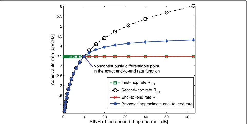
We now present the two-hop interference pricing framework for transmit beamforming. Note that it is straightforward to develop the similar two-hop interfer-ence pricing framework for power control, however, we omit it here to save space. The interference prices are computed based on the Karush–Kuhn–Tucker (KKT) necessary conditions for optimality of the sum-rate max-imization problem. This computation method is crucial for interference pricing-based algorithms to obtain high sum-rates. In the DF relay interference channel, we notice thatRk(ξ¯k,γk(FX))is not continuously differentiable with respect to γk(FX) at the intersection point that makes (1−t)log2(1+γk(FX))equal totlog2(1+ ¯ξk). It follows thatRk(ξ¯k,γk(FX))is not continuously differentiable with respect tofX,mat every point for allm∈K. Therefore, it is challenging to use the KKT necessary conditions for(BF) to find directly even its locally optimal solutions to [62]. To overcome this, we propose to use an approximate func-tion of the end-to-end achievable rate, which we refer to as Rsoft,k(γk(FX))and is a function of{¯ξk}Kk=1,t, andγk(FX).
Some guidelines for selecting Rsoft,k(γk(FX)) are pro-vided. One criterion is thatRsoft,k(γk(FX))is continuously differentiable with respect to γk(FX) at every point to make it possible to use the KKT conditions. Another crite-rion is that the utility function for each user has an appro-priate concavity so that the convergence of the result-ing interference pricresult-ing algorithm is guaranteed [35]. Specifically, Rsoft,k(γk(FX)) has to satisfy the following condition [35]
Ck(Rsoft,k(γk(FX)))−
Rsoft,k(γk(FX))γk(FX)
Rsoft,k(γk(FX)) ∈ (0, 2] .
(14)
The quantityCk(Rsoft,k(γk(FX)))is referred to as the
coef-ficient of relative risk aversion of the utility function Rsoft,k(γk(FX))[63]. The larger value ofCk(Rsoft,k(γk(FX))) indicates that Rsoft,k(γk(FX)) is “more concave” [35]. If these conditions are satisfied, then it is possible to develop an algorithm with asynchronous beamforming vector updates such thatKk=1Rsoft,k(γk(FX))is non-decreasing after each iteration provided that the interference prices are current (i.e., they are updated after each iteration) [16,35].
Defineφk(ξ¯k,t)as the rate-matching received SINR for thekth second-hop link, which is the value of the received SINR at receiverkif the normalized rates on two hops are equal to each other. Specifically, by settingtlog2(1+ ¯ξk)= (1−t)log2(1+φk(ξ¯k,t))and after some manipulation we obtain
φk(ξ¯k,t)=(1+ ¯ξk)1−tt −1. (15) Recall that one challenge is thatRk(ξ¯k,γk(FX)) is not continuously differentiable with respect toγk(FX)at the point γk(FX) = φk(ξ¯k,t). We propose a method to find a class of approximate functions that are continu-ously differentiable at every point and are exactly equal to Rk(ξ¯k,γk(FX)) when γk(FX) ≤ φk(ξ¯k,t) as shown in Figure 2. Using this method, we now provide the following two approximate functionsRip1,k(γk(FX)) and
Rip2,k(γk(FX))in that class
Rip1,k(γk(FX))
= ⎧ ⎪ ⎪ ⎪ ⎨ ⎪ ⎪ ⎪ ⎩
(1−t)log2(1+γk(FX)), ifγk(FX)≤φk(ξ¯k,t)
tlog2(1+ ¯ξk)
+1−t
ln 2
γk(FX)−φk(ξ¯k,t) 1+γk(FX)
, otherwise,
(16)
Rip2,k(γk(FX))
= ⎧ ⎪ ⎪ ⎪ ⎪ ⎪ ⎨ ⎪ ⎪ ⎪ ⎪ ⎪ ⎩
(1−t)log2(1+γk(FX)), ifγk(FX)≤φk(ξ¯k,t)
tlog2(1+ ¯ξk)+ 1−t
ln 2
φk(ξ¯k,t) 2
×
1−exp
2(φk(ξ¯k,t)−γk(FX)) [γk(FX)+1] [φk(ξ¯k,t)+1]
, otherwise.
(17)
The coefficients of relative risk aversion of the approxi-mate functions are given by
Ck(Rip1,k(γk(FX)))
= ⎧ ⎪ ⎪ ⎨ ⎪ ⎪ ⎩
γk(FX) (1+γk(FX))
, ifγk(FX)≤φk(ξ¯k,t)
2γk(FX) (1+γk(FX))
, otherwise,
(18)
Ck(Rip2,k(γk(FX)))
= ⎧ ⎪ ⎪ ⎨ ⎪ ⎪ ⎩
γk(FX) (1+γk(FX))
, ifγk(FX)≤φk(ξ¯k,t)
2γk(FX)(2+γk(FX)) (1+γk(FX))2
, otherwise.
0 10 20 30 40 50 60 1
1.5 2 2.5 3 3.5 4 4.5 5 5.5 6
SINR of the second hop channel [dB]
Achievable rate [bps/Hz] First hop rate R 1,k
Second hop rate R2,k
End to end rate Rk
Proposed approximate end to end rate Noncontinuously differentiable point
in the exact end-to-end rate function
Figure 2Illustration of how we find approximation functions.The achievable rates related to thekth two-hop link as well as the proposed approximate end-to-end achievable rate for the two-hop interference pricing framework are plotted as functions of the SINR of the second-hop link. The SINR of the first-hop link is 10 dB.
Because 0 < γk(FX) < (1+γk(FX))and 0 < γk(2+ γk(FX)) < (1 + γk(FX))2, we have Ck(Rip1,k(γk(FX))),
Ck(Rip2,k(γk(FX))) ∈ (0, 2]. Both Rip1,k(γk(FX)) and
Rip2,k(γk(FX)) are functions of γk(FX), t and {¯ξk}Kk=1. If γk(FX) > φk(ξ¯k,t), then they are larger than Rk(ξ¯k,γk(FX)). The gaps between these approximate func-tions and the exact function increase with γk(FX) and are upperbounded by (1 − t)/ln 2. It is still unclear how to evaluate the quality of the approximate end-to-end functions in terms of exact end-end-to-end sum-rate maximization. Roughly speaking, we expect that the one with a smaller gap with the exact function, which is Rip2,k(γk(FX)) in this case, outperforms the other. Although this prediction is confirmed by our numerical results, we do not have a formal proof. Note that the two approximate functions can be used to develop distributed two-hop interference pricing algorithms for solving(BF) and (PC). The next sections present the details of how such algorithms are developed usingRip1,k(γk(FX)). The algorithms corresponding to the use ofRip2,k(γk(FX,pX)) can be developed in the same way.
Distributed algorithm development
Let(BF −IP)be the relay beamforming design prob-lem for approximate end-to-end sum-rate maximization associated withRip1,k(γk(FX)). This can be formulated as
(BF−IP): max
FX∈FX
K
k=1
Rip1,k(γk(FX)). (20)
This section describes a distributed two-hop interference pricing algorithm for solving(BF−IP).
We first present the computation method of interfer-ence prices. Consider a set of dual variablesλ1,. . .,λK ≥0 the constraints fX,k2 ≤ pmaxX,k for k ∈ K. The KKT conditions for(BF−IP)are
∂Rip1,k(γk(FX)) ∂f∗X,k +
m=k
∂Rip1,m(γm(FX))
∂f∗X,k =λkfX,k, (21)
λk(fX,k2−pmaxX,k )=0. (22)
Recall that for the kth second-hop link, we define the signal power as Ak(FX) = f∗X,khk,kh∗k,kfX,k and the sum interference power as Ik(FX) = q=kfX,∗qhk,qh∗k,qfX,q. Define the following values for allk∈K
θBF,ip1,k(FX)= −
∂Rip1,k(γk(FX)) ∂Ik(FX)
, (23)
βBF,ip1,k(FX)=
∂Rip1,k(γk(FX)) ∂Ak(FX)
. (24)
Note that θBF,ip1,k(FX) represents the marginal decrease in Rip1,k(γk(FX)) per unit increase in Ik(FX). Thus, we can interpretθBF,ip1,k(FX)as the cost charged to any relay
interference price at receiverk. Similarly,βBF,ip1,k(FX) rep-resents the marginal increase in Rip1,k(γk(FX)) per unit increase inAk(FX). We can also interpret it as the desired signal reward at receiverk. After some manipulation, we obtain
θBF,ip1,k(FX)
= ⎧ ⎪ ⎪ ⎪ ⎨ ⎪ ⎪ ⎪ ⎩
(1−t) ln 2
γk2(FX)
Ak(FX)[ 1+γk(FX)]
, ifγk(FX)≤φk(ξ¯k,t)
(1−t) ln 2
γk2(FX)[ 1+φk(ξ¯k,t)] Ak(FX)[ 1+γk(FX)]2
, otherwise,
(25)
βBF,ip1,k(FX)=
θBF,ip1,k(FX)
γk(FX)
. (26)
To computeθBF,ip1,k(FX), receiverkitself estimatesγk(FX) and Ak(FX). In addition, it obtains φk(ξ¯k,t) from relay k via a feedforward channel. We need θBF,ip1,k(FX) and γk(FX)to computeβBF,ip1,k(FX).
We next present in detail how to use interference prices and desired signal rewards in the proposed relay beam-forming design. Applying the chain rule, we can show that (21) is equivalent to
βBF,ip1,k(FX)
∂Ak(FX) ∂f∗X,k −
m=k
θBF,tip1,m(FX) ∂Ik(FX)
∂f∗X,k =λkfX,k.
(27)
Equivalently, ⎡
⎣βBF,ip1,k(FX)hk,kh∗k,k−
m=k
θBF,tip1,m(FX)hm,kh∗m,k ⎤ ⎦
XBF,k(FX)
×fX,k =λkfX,k (28) The proposed algorithm is iterative and asynchronous. In each iteration, only one relay k is selected randomly to update its transmit beamformer by solving the following problem
(BF−N Pk): max
s∈FX,k
s∗XBF,k(s;FX,−k)s. (29)
According to Proposition 3 in [35], the resulting algorithm based on Rip1,k(γk(FX)) is guaranteed to converge to a stationary point of(BF−IP).
When the relays are equipped with multiple antennas, i.e.,NX>1, in general,(BF−N Pk)is a nonlinear opti-mization problem, and hence finding its globally optimal solutions may be time-consuming. To overcome this limi-tation, we adopt the method in [17] to propose a modified algorithm with a simple beamforming update rule. In par-ticular, in each iterationn ≥ 1, we propose to replace
XBF,k(F(Xn))byYBF,k(F(Xn−1)), which is defined as
YBF,k(F(Xn−1))=βBF,ip1,k(f(X,n−k1);F(X,n−−1k))hk,kh∗k,k
−
m=k
θBF,ip1,m(f(X,nm−1);F(X,n−−1m))hm,kh∗m,k.
(30)
Both βBF,ip1,k(fX,(nk−1);F(X,n−−1k)) and θBF,ip1,m(fX,(nm−1);F(X,n−−1m)) form= kare computed in the previous iteration, there-foreYBF,k(FX(n−1)) is independent ofs. In iterationn, the selected relay kneeds to solve the following problem to determinef(X,n)k
(BF−AN Pk): max
s∈FX,k
s∗YBF,k(FX(n−1))s. (31)
We can show that the solution is f(X,n)k =
νmax(YBF,k(F(Xn−1))), the eigenvector corresponding to the maximum non-negative eigenvalue of YBF,k(F(Xn−1)). If
YBF,k(F(Xn−1)) has no non-negative eigenvalue, then the relay does not update its beamforming.
Algorithm. Distributed two-hop interference pricing algorithm for relay beamforming design
• Initialization: each relayk feeds forwardφk(ξ¯k,t)to receiverk and selects a random beamformerf(X,0)k.
• Iterationn(n≥1): the following updates are performed
– Interference price: each receiver k computes θBF,ip1,k(F(Xn−1))and broadcasts to all the relays.
– Desired signal reward : each receiver k computesβBF,ip1,k(FX(n−1))andγk(F(Xn−1)). Then it feeds back the information to relayk. – Beamforming vector: a relay k is randomly
selected to updatef(X,n)k=νmax(YBF,k(F(Xn−1))).
Although we have not been able to prove analytically the convergence of the modified algorithm, we observed from our numerical results that it converges in all the cases considered.
information on the sum-rate performance are interesting topics for future research.
Note that our proposed algorithm is different from the prior algorithm in [16]. Prior work in [16] is able to max-imize the sum-rates on a single hop, i.e., either the first hop or the second hop. It ignores {γk{1}}Kk=1 and t and hence results in two-hop rate mismatch. On the contrary, our approach is able to take into account{¯ξk}Kk=1andtto alleviate two-hop rate mismatch to obtain higher end-to-end sum-rates. In addition, the relays need to feedforward information to their associated receivers.
Recall that whenNX > 1, then(BF −N Pk)is a non-linear optimization problem, of which finding the globally optimal solutions may be time-consuming. Although the modified algorithm can approximately solve(BF−N Pk), we are unable to prove analytically the convergence of the modified algorithm. This challenge may not appear when we focus on updating only the actual transmit powerpX, for example, when the relays have a single antenna or when we update only the norm of the relay precoders but not their shape. For notational convenience, we denote FX = √pXF¯X, whereF¯Xwith¯FX2F = 1 represents the shape of the transmit precoders at the relays. Given fixed beamforming vectors F¯X, we define the effective chan-nel from relay k to receiver mash¯m,k h∗m,k¯fX,k ∈ C fork,m ∈ K. We can always formulate an interference pricing-based relay power control problem to determine pXgiven the knowledge of effective channelh¯m,k, which is referred to as(PC−IP)and is a special case of(BF − IP). Note that in the relay beamforming design prob-lem, each relay needs to determine simultaneously several complex numbers to update its beamforming vectors. In the relay power control algorithm, each relay needs to determine only a positive real number for its transmit power value. This may simplify the implementation of the resulting algorithm. Specifically, by relaxing the power range constraints and using similar steps for finding high-quality solutions for(BF−IP), we can develop a two-hop interference pricing power control algorithm for deter-miningpX. This algorithm is iterative and asynchronous where in each iteration only one relay is allowed to update the transmit power. Letkbe the index of the selected relay for transmit power update in iterationn≥1. One impor-tant characteristic of this algorithm is that the candidate value for power update in iterationnis provided in closed form as
where
θPC,ip1,k(pX)
= ⎧ ⎪ ⎪ ⎨ ⎪ ⎪ ⎩
(1−t) ln 2
γk2(F¯X,pX)
pX,k|¯hk,k|2[1+γk(F¯X,pX)], ifγk( ¯
FX,pX)≤φk(ξ¯k,t)
(1−t) ln 2
[1+φk(ξ¯k,t)]γk2(F¯X,pX)
pX,k|¯hk,k|2[1+γk(F¯X,pX)]2, otherwise.
(33)
Incorporating back the power range constraints, we pro-pose that relaykupdates its transmit power asp(X,n)k= ¯p(X,n)k only if 0 ≤ ¯p(X,n)k ≤ pmaxX,k. According to Proposition 2 in [35], the iterative and asynchronous interference pric-ing algorithm for power control is guaranteed to converge to a stationary point of(PC−IP). Note that this algo-rithm does not maximize directly the exact end-to-end sum-rates. Thus, its convergence in terms of exact end-to-end sum-rate maximization is not guaranteed. In our simulations, however, this algorithm converges in all the considered scenarios.
Discussion
In this section, we provide some remarks on the order of optimization, distributed implementation, and complexity analysis of the algorithm.
Order of optimization
There is another optimization order where the relays are first designed to maximize the achievable sum-rates on the second hop. Then interference pricing is used to take into account the timesharing and second-hop rates in the design the transmitters to approximately maxi-mize end-to-end achievable rates. Depending on channel realizations on two hops, one order of the optimization outperforms the other in terms of end-to-end sum-rate maximization and vice versa. We prefer our order of optimization due to overhead considerations. Specifically, as the relays themselves estimate the received SINR on the first hop, our proposed order of optimization only requires the receivers estimate and send back the second-hop SINR to the relays to perform two-second-hop rate matching. The other order of optimization, however, requires the relays and receivers to send back the SINR on two hops to the transmitters to perform two-hop rate-matching.
Distributed implementation
The implementation of the proposed algorithm requires that the transmissions on each hop start at the same
¯
p(X,n)k= ⎧ ⎪ ⎪ ⎪ ⎪ ⎪ ⎨ ⎪ ⎪ ⎪ ⎪ ⎪ ⎩
(1−t)
ln 2
γk(F¯X,p(Xn−1)) p(X,n−k1)
1
m=kθPC,ip1,m(pX(n−1))|¯hm,k|2
−1
p(X,n−k1)
γk(F¯X,p(Xn−1))
, ifγk(F¯X,pX(n−1))≤φk(ξ¯k,t)
(1−t)
ln 2
γk(F¯X,p(Xn−1)) p(X,n−k1)
[ 1+φk(ξ¯k,t)]
m=kθPC,ip1,m(pX(n−1))|¯hm,k|2
−1 1/2
p(X,n−k1)
γk(F¯X,p(Xn−1))
, otherwise,
time and end at the same time. The relays are informed about the predetermined common time sharing value t. The transmitters need to agree with each other on the transmission strategy on the first hop as listed in Step 1. Each relay k itself estimates the received SINR on the first hop ξ¯k and computesφk(ξ¯k,t). Each relay k feeds forwardφk(ξ¯k,t)to receiverkand selects a random beam former f(X,0)k. In each iteration n ≥ 1, the follow-ing updates are performed in the predetermined order: (i) each receiver kcomputes θBF,ip1,k(F(Xn−1)) and broad-casts it to all the relays, (ii) each receiver k computes βBF,ip1,k(F(Xn−1))andγk(F(Xn−1))and then sends them back to relayk, and (iii) a relayk0is randomly selected to update its beamforming vectorf(X,n)k
0 =ν max(Y
BF,k0(F (n−1) X )). Note that this implementation requires feedback and feedfor-ward mechanisms between the relays and receivers. It also requires a little coordination among the relays to deter-mine which relay is selected to update its beamforming vector in each iteration.
Complexity analysis
For simplicity in the complexity analysis of the algorithm, we assume thatNk = NX fork ∈ K. Note that the ini-tialization of the algorithm requires the estimation of the received SINR on the first hopξ¯k and then the compu-tation of φk(ξ¯k,t) based on (15). Moreover, this step is performed only once at the beginning. Thus, in the com-plexity analysis, we ignore the initialization and focus on the iterations. Recall that in each iteration, only one relay is allowed to update its beamformer. We now provide a rough complexity analysis of the individual steps in each iteration. First, in the interference price update step, we need to computeIk(FX)=
q=k|f∗X,qhk,q|2andAk(FX)=
f∗X,khk,k2 for eachk ∈ K, which allow us to compute γk(FX) according to (7) and thenθBF,ip1,k(FX) according to (25). Thus, this step yields a complexity ofO(K2NX). Second, in the desired signal reward update step, we need to compute βBF,ip1,k(FX) from θBF,ip1,k(FX) and γk(FX) according to (26). This step can be ignored from the com-plexity analysis. Third, in the beamforming vector update step, we need to computeYBF,k(F(Xn−1))according to (30) only for the selected relay k. This computation has the complexity ofO(KNX2). We also need to perform an eigen-value decomposition of YBF,k(FX(n−1) ∈ CNX×NX, which yields a complexity ofO(NX3). Thus, this step has a com-plexity of O(KNX2)+O(NX3). In short, the per-iteration complexity of the algorithm is O(K2N
X) + O(KNX2) + O(NX3).
Numerical results
This section provides Monte Carlo simulation results to evaluate the two-hop sum-rate performance of the pro-posed algorithms in a multicell cellular network setting.
Base station antennas Relays
Single-antenna mobile stations Coordinated sectors
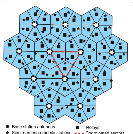
Figure 3System model under consideration for the simulations presented in this article.Each cell is sectorized into six sectors in the given pattern. The universal frequency reuse is deployed in the network. The focus is on the triangular area in the center of the network for which we compute the average sum of the end-to-end achievable rates.
Universal frequency reuse is deployed in the network. The cells are sectorized such that each cell consists of six sec-tors as shown in Figure 3. The cell radius isr = 866 m. More details in the simulation setting such as channel model parameters are referred to [6] to save space. The three sectors of interest are in the marked triangular area in the center of the network. Treating the interference from the other sectors than the ones of interest as additive
sector corner
Base station user-ring
cell corner
Relay
2r / 3 r / 3
d
Figure 4Illustration of user generation in the sectors of interest. Users are generated randomly on rings centered at their
Figure 5Investigation of the convergence of the proposed distributed relay beamforming algorithm.The proposed two-hop interference pricing beamforming converges well in terms of maximizing sum of the approximate end-to-end achievable rates.
18 20 22 24 26 28 30 32 34 36
0.5 1 1.5 2 2.5 3 3.5
Relay transmit power [dBm]
Average end−to−end sum−rates [bps/Hz]
Proposed two-hop intf. pricing relay BF Second-hop intf. pricing relay BF
IEEE 802.16j single-antenna relaying Zero-forcing like relay beamforming Maximal ratio trans. relay beamforming
(2,2,I) configuration
(I,I,I) configuration
(3,3,1) configuration
Gaussian noise, we compute the average two-hop sum-rates of the three pairs in the sectors of interest. The base stations use MRT beamforming to send data to their associated relays.
Figure 4 illustrates how users are generated in a sector and the location of the fixed relay. The distance from the relay in each sector to the base station is equal to two-third of the cell radius. The users in each sector of interest are generated randomly on the rings centered at their corre-sponding base station with radiusd. Users in other sectors are generated randomly. We consider different antenna configurations, denoted as (M,N, 1), i.e., M directional antennas in each sector at a base station are used to serve a single user at a time via a dedicated relay withN omni-directional antennas. All relays have a common value of maximum transmit powerPmax. We consider two sets of experiments: (i) varying relay power and (ii) moving users. In the first set of experiments, we assume that the users of interest moving on rings withd = 826 m are considered as cell edge users. The resulting plots show the average two-hop sum-rates as functions ofPmax. In the second set of experiments, we plot the average two-hop sum-rates as functions ofdwhen all the relays havePmax=37 dBm.
For comparison, we implement several baseline relay beamforming algorithms. While the ZF-like beamforming minimizes the sum of interference power each relay cause to the other receivers of interest, the MRT beamform-ing maximizes the desired signal power each relay sends to its associated receiver. We also implement the beam-forming algorithm resulting from the direct application of single-hop interference pricing beamforming in [16]
720 740 760 780 800 820 840
1.8 2 2.2 2.4 2.6 2.8 3 3.2 3.4 3.6
Distance from MS to BS [m]
Average sum of two−hop achievable rates [bps/Hz]
(2,2,1) configuration Relay
position
Towards base station (3,3,1)
configuration
Second-hop interference pricing Two-hop intf. pricing using Rrip2,k
Two-hop intf. pricing using Rrip1,k
Figure 7End-to-end achievable rates as functions of the distance from users’ location to the base stations for (3,3,1) and (2,2,1) configurations.The algorithm based onRip2,k(FX)slightly
outperforms the algorithm based onRip1,k(FX)in terms of
maximizing the exact end-to-end sum-rates.
10 15 20 25 30 35
0.65 0.7 0.75
Relay transmit power [dBm]
Average two−hop sum−rates [bps/Hz]
Two−hop interference pricing PC Second−hop interference pricing PC IEEE 802.16j with the maximum power
10 15 20 25 30 35
0.39 0.4 0.41 0.42 0.43 0.44 0.45
Relay transmit power [dBm]
Average two−hop sum−rates [bps/Hz]
Two−hop interference pricing PC Second−hop interference pricing PC IEEE 802.16j with the maximum power
10 15 20 25 30 35
0.21 0.215 0.22 0.225 0.23 0.235 0.24 0.245
Relay transmit power [dBm]
Average two−hop sum−rates [bps/Hz]
Two−hop interference pricing PC Second−hop interference pricing PC IEEE 802.16j with the maximum power a
b
c
to the second-hop, which we refer to as the second-hop interference pricing beamforming.
We now investigate the convergence of the proposed distributed relay beamforming algorithm. Figure 5 shows the sum of the approximate end-to-end rates over iterations for the proposed two-hop interference pric-ing beamformpric-ing with the approximate rate function Rip2,k(γk(FX))given in (17). We notice that the approxi-mate end-to-end sum-rates are not decreasing over iter-ations of the proposed relay beamforming algorithm. Moreover, the proposed algorithm converges quite fast and saturates within 20 iterations.
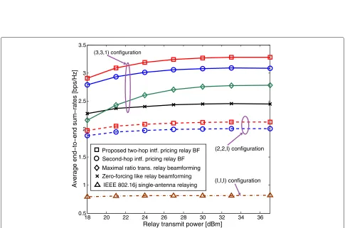
Figure 6 presents simulation results for different antenna configurations. First, we notice that the proposed algorithm outperforms the second-hop interference pric-ing algorithm in both cases: 5.8% gain in the (2, 2, 1) case and 6.4% gain in the(3, 3, 1)case. These gains come from the consideration of the first-hop performance and the timesharing value, which alleviates rate mismatch. Note that our proposed algorithm requires only addi-tional overhead for feed-forwarding φk(ξ¯k,t) from each relay k to receiver k in the initial step. Since the chan-nels between base stations and relays are expected to be stable, such additional overhead is negligible. Second, for the(3, 3, 1)configuration, the two-hop interference pric-ing relay beamformpric-ing provides 34% gain over the MRT beamforming and 18% gain over the ZF-like beamform-ing. Finally, the proposed algorithm provides large gain over IEEE 802.16j single-antenna relay communication: 160% in the (2, 2, 1) case and 302% in the (3, 3, 1) case. This highlights the benefits of multiple-antenna relays.
Figure 7 shows the simulation results of a moving user experiment for the two-hop interference pricing beamforming design algorithms using the two exam-ples of approximate end-to-end rates as compared to the second-hop interference pricing. We notice that the two-hop interference pricing algorithms provide large gains over the second-hop interference pricing for all range of user locations. Moreover, the two-hop interference pric-ing beamformpric-ing design withRip2,k(γk(FX)always slightly outperforms that with Rip1,k(γk(FX)as expected. This is becauseRip2,k(γk(FX)provides a better approximation of the end-to-end rate than doesRip1,k(γk(FX). This means the quality of the resulting solutions by the proposed two-hop interference pricing beamforming design depends on the selection of the approximate end-to-end rate function. The same trend holds for other antenna cases although the simulation results are not shown here to save space.
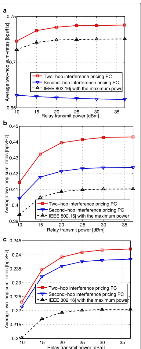
The last experiment is on power control for the single-antenna relay interference channel with M = N = 1. For comparison, we implement two reference strategies: (i) second-hop interference pricing algorithm and (ii) IEEE 802.16j with the maximum power. In the second-hop interference pricing algorithm, we apply directly the prior
interference pricing algorithm for the single-hop interfer-ence channel in [15] for the second hop. In the maximum-power IEEE 802.16j strategy, the relays behave egoistically by using their maximum power to increase the desired sig-nal power to their associated receivers while causing large interference to unintended receivers. Figure 8 provides the results ford = 836 m (cell-edge user case) andt ∈ {0.70, 0.90, 0.95}. Note that the second-hop interference pricing algorithm may perform worse than the maximum-power IEEE 802.16j strategy. This confirms that the max-imization of the second-hop sum-rates may cause more mismatch between the rates on two hops, degrading the two-hop sum-rate performance. In addition, our proposed two-hop interference pricing algorithm always outper-forms the other algorithms for all considered values oft. The reason is that our proposed algorithm can take into accounttand{¯ξk}Kk=1into the relay power control to alle-viate two-hop rate mismatch while the other algorithms cannot.
Conclusions
We proposed an algorithm for designing the transmission parameters at the transmitters and relays in the DF relay interference channel to maximize end-to-end sum-rates. The algorithm copes with both interference and mismatch between the rates on two hops, two main challenges in designing the DF relay systems. Our key contribution is the two-hop interference pricing framework that allows for the integration of information about the first-hop per-formance and timesharing value in the computation of interference prices on the second hop for design the relays. The proposed algorithm allows for distributed implemen-tation, making it suitable for practical systems. Simula-tions showed that the proposed algorithm obtains higher end-to-end sum-rates than the existing strategies, includ-ing the na¨ıve approach of applyinclud-ing independently the single-hop interference pricing algorithms on two hops.
Competing interests
RH is also President and CEO of MIMO Wireless Inc. The terms of this arrangement have been reviewed and approved by the University of Texas at Austin in accordance with its policy on objectivity in research.
Acknowledgements
This study was supported by a grant from Huawei Technologies, Inc.
Received: 21 June 2012 Accepted: 11 January 2013 Published: 20 February 2013
References
1. O Simeone, O Somekh, Y Bar-Ness, HV Poor, S Shamai, inProceedings of the Allerton Conference on Communication, Control, Computing. Capacity of linear two-hop mesh networks with rate splitting, decode-and-forward relaying and cooperation, (Monticello, IL, 2007)