a.School of chemistry, St Andrews University, Fife KY16 9ST, United Kingdom. E-mail: [email protected]
b.Department of Chemical and Biomolecular Engineering, Yonsei University, Yonsei-ro 50, Seodaemun-gu, Seoul, 120-749, Republic of Korea. E-mail: [email protected]
c.Department of Materials Science and Engineering, Yonsei University, Yonsei-ro 50, Seodaemun-gu, Seoul 120-749, Republic of Korea.
§These authors contributed equally to this work.
† Electronic Supplementary Information (ESI) available: Additional SEM, Cross-section SEM, TEM, EDS and single cell characterization data. See
DOI: 10.1039/x0xx00000x
ARTICLE
Received 00th January 20xx, Accepted 00th January 20xx
DOI: 10.1039/x0xx00000x
www.rsc.org/
Corn-cob like Nanofibres as Cathode Catalysts for an Effective
Microstructure Design in Solid Oxide Fuel Cells
Yukwon Jeon
a,b,§, Jae-ha Myung
a,§, Sang-hoon Hyun
c, Yong-gun Shul
b,* and John T. S. Irvine
a,*
An efficient cathode for solid oxide fuel cell (SOFC) is mainly determined by the oxygen reduction reaction (ORR) activity of the mixed materials. We demonstrate a new microstructure design through a nanofibrous electrode based on an unique corn-cob structure. One-step process to produce a corn-cob ceramic nanofiber of La0.8Sr0.2MnO3 (LSM) and Y2O3-stabilized ZrO2 (YSZ) is introduced by an electrospinning equipped with a coaxial nozzel. From the microscope analysis, perfect corn-cob nanofibers are finely produced with the diameter of 350 nm for a core and nanoparticles (30-40 nm) stacked on the surface like as a core-shell structure. The cathode fabricated by nanofibers with LSM outside and YSZ inside (YSZ@LSM) shows the best maximum power density of 1.15 Wcm-2
at 800 o
C with low polarization resistance, which is higher than the reverse core and shell positions (LSM@YSZ) and even the commercial LSM-YSZ. This better outcome is more obvious at the elevated temperature due to the accelerated catalytic activity. Therefore, we could find the insight into the key factors enhancing the ORR activity and single cell performance in terms of not only the nanofibrous core@shell structure but also more reaction active sites from the optimum catalyst position at the designed corn-cob nanofibers based cathodes.
1. Introduction
The demand for clean, safe, economical and sustainable energy source has inspired a great interest in fuel cell technologies that directly converted
chemical energy to electrical energy.1-4 Among many different fuel
cells, solid oxide fuel cell (SOFC) is one of the most promising electric power generator for delivering high electrical and fuel
regeneration efficiency.5-8 SOFC is composed from a dense
electrolyte layer that is sandwiched between two porous electrodes of cathode and anode. The cell performance is mainly limited by the electrolyte resistance and the oxygen electrode kinetics at the cathode. Therefore, mixed conducting materials must be designed for a cathode, which have catalytic activity and electrical conductivity, preferably also with an ionic conductivity. Commonly, La1-xSrxMnO3 (LSM) with yttria-stabilized zirconia (YSZ) has been used since it extends their electrochemical region and minimize the difference of thermal expansion coefficient (TEC) at the 2D interface
between the electrolyte and 3D bulk electrode.9-12
For the conventional cathode, however, these are mechanically
mixed and sintered at high temperature onto a dense electrolyte. Unfortunately, this simple method is difficult to control the
composition distribution and architecture of the electrode. As the
cathode reaction only take place at the three-phase boundary (TPB) sites where LSM-YSZ-gas phase meeting together, the microstructure design is an important process to increase the TPB sites from larger active sites and better connectivity for optimizing
the cathode electrochemical reaction.13-15
Many efforts have been made to optimize the microstructure of the cathode in order to gain an satisfied polarization resistance by changing various mixed ion/electron
conductors,16-17 production methods (infiltration, impregnation),18-20
preparation conditions (temperature, time , etc),21 and material morphology (particle size and shape).
Recently, there are several reports on microstructure design for electrochemistry devices by using 1-D dimensional nanomaterials such as nanoparticles, nanowires, and nanofibers, due to their
unique properties.22-26 Among these, nanofibers have been
attractive to the SOFC field because of their highly porous feature with large surface-to-volume ratio and surface areas highly exposed
to the surrounding environment.27-28 To fabricate a one dimensional
continuous long nanofiber, electrospinning method by employing a strong electric field to an inserting polymeric liquid source is currently the most powerful technique that is fast and efficient to
widely apply in many areas.29-30 In our previous study, nanofibrous
Please do not adjust margins
performance and even better durability.28,31 Furthermore, Mingjia
Zhi et al. reported an YSZ scaffold mat infiltrated with LSM as a
mixed (ionic and electronic) conducting cathode.32 This showed an
improved oxygen reduction properties by reducing the polarization resistance, which is due to the continuous path of charge transport for both oxide ions and electrons. However, it needs still many processes to fabricate a desired cathode structure, which limited the commercialization of the nanofibrous electrode in the SOFC field.
The position of each cathode materials has also become another crucial issue to design an effective microstructure for high performance SOFC. A core-shell structure may develop an ideal microstructure with improved phase contiguity, homogeneity, and
maximized TPB density.33-34 However, there is no example of
core-shell like nanofibrous structure with both sides being ceramic material because of their different shrinkage and sintering rate.
Here in, we introduce a unique corn-cob like (core-shell) ceramic nanofibers by employing a coaxial electrospinning method which is a one-step process for the production of nanofibrous cathode in SOFC. The cathodes fabricated by this strategy do not need any other infiltration process to obtain continuous conducting nanofibrous structure for the YSZ@LSM composite. Additionally, the core and shell materials were able to alternate, and the role of each material depending on their positions at core and shell was investigated. As from the optimization of the position of LSM and YSZ, our new nanofibrous structure showed an improved catalytic
and conductive properties from reduced polarization resistance and high performance, which enables us to successfully achieve an ideal microstructure design of the cathode with an understanding of their mechanisms.
2. Experimental
Synthesis of corn-cob ceramic nanofiber. Two different corn-cob
ceramic nanofibers with the compositions of La0.8Sr0.2MnO3 (LSM)
and 8% Y2O3-stabilized ZrO2 (YSZ) were designed reversely for the
core and shell, named as YSZ@LSM and LSM@YSZ nanofibers. The spinning solutions were prepared by dissolving each stoichiometric metal precursors to the mixture of dimethylformamide (DMF) and ethanol with the weight ratio of DMF to ethanol of 8:2 and that of the mixture to the solvent of 1:5. The amount of the precursors were calculated to fix the final weight ratios of with around 50:50 for both YSZ@LSM and LSM@YSZ nanofibers. Then, a polymeric ingredients of polyvinylpyrrolidone (PVP; MW=1,300,000) was added and homogenized via vigorous stirring for 6 h at room temperature. To achieve a corn-cob nanofibrous structure, different weight ratio of PVP and mixed metal solutions were used to avoid the mixing of the core and shell precursors. The weight ratio for the shell was 1:1.5 of PVP and metal nitrates, which is higher than of the core with the value of 1:1.
Dual ceramic nanofibers were synthesized via electrospinning method by coaxial tip system. As shown in Figure 1, a dual tip was
2 | J. Name., 2012, 00, 1-3 This journal is © The Royal Society of Chemistry 20xx
set up to separately insert each polymer and metal precursor composite solutions for the core and shell. The sizes of the outer and inner tips were 17 G and 23 G with an inner diameter of 1.07 mm and 0.33 mm with the shell thickness of 0.22 mm, respectively. The distance between the dual tip and drum collector was approximately 15 cm. During the electrospinning, the drum with a tracing paper was constantly rotated with a speed of 150 rpm (revolution per minute). The humidity and temperature were kept below 30% RH and approximately 35 °C, respectively. Each solutions
were electrospun by applying a high voltage of 18 kV at 10 µL min-1
to produce well-structured core@shell metal precursor/PVP
composite nanofibers. Then, these are stabilized at 400 oC and rate
of 1 °C min-1 in air atmosphere for 3 h, and heat-treated at 1200 oC
in air atmosphere for 6 h at a rate of 2 °C min-1 to completely remove the nitrate and PVP, as well as to form interconnected ceramic nanoparticles as a nanofiber structure, separately with the core and shell regions.
Physical characterization. The morphology of the prepared materials was determined using scanning electron microscopy (SEM, JEOL JSM-6701F) operated at 15 kV and high-resolution transmission electron microscopy (HR-TEM, JEOL JEM-2100F) operated at 200 kV. High-resolution transmission electron microscopy (HR-TEM) images as well as selected area electron diffractions (SAED) were examined using a JEOL 2010 TEM operated at 200 kV. The STEM (Spherical Aberration Correction Scanning Transmission Electron Microscope) image using a HAADF detector, the elemental results and line scans by the Electron Energy Loss Spectrometry (EELS) and the elementary Energy Dispersive X-ray Spectrometry (EDS) were performed by the JEM-ARM 200F. All samples were prepared by placing samples onto a carbon-coated copper grid. XRD Analysis of X-ray diffraction was performed with Rigaku Miniflex AD11605 operated with a Cu Kα source
(λ = 1.541 Å) at 40 kV and 100 mA. The Brunauer-Emmett-Teller
(BET) surface area, pore volume, and pore diameter of the cathodes were determined using a distribution graph of N2 adsorption-desorption at 77 K (Micromeritics ASAP 2010) using the BET equation.
Half-cell and SOFC single cell Measurements.
For the half-cell test, 1mm-YSZ pellets were prepared by uni-axial
pressing and sintering at 1450 oC. After smoothening both sides of
the pellets, nanofibrous cathodes were formed on both sides by
screen-printing and firing at 1200 oC. Then, impedance data by using
Solartron were measured from 650 to 850 oC in air atmosphere
between 106 and 0.1 Hz.
The SOFC single cells were prepared as following. Ni-YSZ based anode supports were prepared by uni-axial pressing and pre-sintering at 1150 oC. Then, YSZ electrolyte was coated by
dip-coating and sintering at 1400 oC. After polishing one of the pellet
sides by sand paper, the prepared cathode materials were
screen-printed and fired at 1200 oC. The single cells were measured by
Solartron 1280 B at the range of 650 to 850 oC with humidified H
2
(50 cc min-1 at standard ambient temperature and pressure) at the
anode and air (500 cc min-1 at standard ambient temperature
and pressure) at the cathode.
3. Results and discussion
Corn-cob ceramic nanofibers. In Figure 1(a), we proposed a novel electrospinning method to produce a perfect corn-cob ceramic nanofibers for the use as a cathode material in SOFC. In step 1, two precursors for LSM or YSZ were prepared by a different concentration of polymer (polyvinylpyrrolidone, PVP) to prevent
mixing of the core and shell materials.35-36 In step 2, each core and
shell precursors were finely electrospun by a dual nozzel on a rotating tracing paper (Figure 1(b)). Figure 1(c) shows the well-made electrospun dual metal precursor/PVP nanofibers with a continuous long met feature. As shown in Figure S1, the diameters were uniform with distributions of 500-600 nm for both LSM@YSZ and YSZ@LSM composites. In step 3, the electrospun dual metal precursor/PVP nanofibers were stabilized at 400 oC for 6h to
remove all the polymer components, and then calcinated at 1200 oC
for 6h to produce a cermic corn-cob nanofibers. From the SEM image in Figure 1(d) and Figure S2, we observed a well-produced nanofiber web for both composites. The diameters reduce one third due to the polymer removal and ceramic sintering but preserve the morphologies of the nanofibrous web structure.
Figure 2 shows the magnified SEM images for the fine LSM@YSZ and YSZ@LSM composite nanofibers to observe the nanofiber surfaces. All nanofibers were extremely long and well-connected without many disconnections. Interestingly, we found that both nanofibers reveal a unique corn-cob like structure where the core material is located in the middle and covered by stacking nanoparticles as a shell. Both composites showed a similar
morphology with just a small size differences. Overally seen from
Figure 2a and 2c, the average diameters of corn-cob nanofibers can be controlled within the range of 350-400 nm by the presented dual nozzel and electrospinning conditions. When the shell is composed of LSM on the dual nanofibers, the average diameter was slightly thicker by about 50 nm than the nanofibers with the YSZ shell. This difference could be explained from the particle sizes on the surface, as shown in Figure 2b and 2d. The LSM particles at the shell were
around 20 nm w hile the YSZ particles at shell were about 10 nm,
resulting in a different diameter of the corn-cob nanofibers due to these different ceramic sintering rate at the same calcination condition.
Please do not adjust margins
region, which provides a strong evidence of the formation of the core-shell like feature. It was found that the thicknesses of the shells were around 50 nm at the end of highly interconnected nanoparticles while the core was around 200 nm. Furthermore, It was clearly observed that shells at the corn-con nanofibers were made up of spherical nanoparticles with an average size of approximately 15 nm in diameter, displaying a corn-cob like structure as we expected.
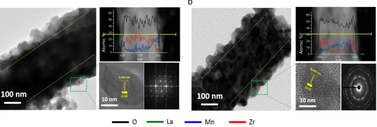
The core and shell components of the YSZ@LSM and LSM@YSZ nanofibers are not easily differentiable because LSM and YSZ exhibit a similar imaging contrast. Therefore, the elemental profiles in the high-angle annular dark field (HAADF)–scanning transmission electron microscopy (STEM) images by simulating line scan across the corn-cob-like nanofibers were carried out to distinguish the core and shell. As shown in each right upper side panel of Figure 3(a) and 3(b), a perfect corn-cob structure similar to a core@shell was obtained by the evidance of the signals from the shell materials (La and Mn) detected across the entire nanofibers of around 70 nm whereas signals of the core materials (Zr and Y) were only obtained across the core of 200 nm. This observation was also seen in Figure 3(b) for the opposite position of LSM and YSZ, indicating that both compositions achived a corn-cob like structure. Furthermore, the weight ratios were confirmed in detail by focusing a specific region for the EDS analysis as in Figure S3. Each compositions (Table S1) of LSM (La, Mn, Sr and O) and YSZ (Zr, Y and O) were approximatley 50:50 in weight ratio as we designed and used in the commercial cathode to focus on the morphology. There is another evidence of the corn-cob structure from the magnified HR-TEM images and its selected area electron diffraction (SAED) spot patterns in each right lower side panel. These are from the nanoparticles in each shells which should be LSM for Figure 3(a) and YSZ for Figure 3(b). These results revealed the exact interplanar distances of each materials with the value of 0.265 nm for LSM and 0.303 for YSZ, from the regular lattice fringes along [110] and [111] directions, respectively. Moreover, the SAED spot patterns were also obviously assigned to LSM and YSZ, providing an additional proof of the corn-cob structure.26,37
Figure 4 present the XRD patterns of the LSM@YSZ and YSZ@LSM corn-cob nanofibers, commercial LSM-YSZ. As we designed a
separated core and shell structure, all dual nanofibers perfectly exhibited the original peak positions of LSM and YSZ. These can be assigned from each commercial materials as reference values, corresponding to the (hkl) indices (100), (110), (111), (200), (210), (211), (220) for LSM and (111), (200), (220), (311), (222), (400) for
YSZ, respectively.26,31 Another point of view, an obvious formation of
a separated core and shell structure can be explained from the difference in the peak intensities which indicates different calculated particle sizes. It is possible to understand that the particles sizes of the shell materials were relatively smaller than when it was located in the core, due to better distribution and lower aggregation at the surface. It also supported an establishment of the corn-cob nanofiber structure. Therefore, we could finally state that a perfect corn-cob structure of both LSM@YSZ and YSZ@LSM was possible to produce for the use as a cathode material in SOFC.
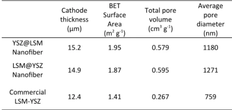
Half-cell and SOFC single cell tests. To evaluate the electrodes composed by the synthesized corn-cob nanofibers, YSZ@LSM and LSM@YSZ nanofibers were deposited on both sides of the YSZ electrolyte for a half cell test and one side of the Ni-YSZ/YSZ single cell for a SOFC single cell test. From the SEM image of the cross-section in Figure S4, the electrode layers on the single cells were perfectly stacked by the corn-cob nanofibrous webs with a slight sintering. We could observe a unique pore structure including larger pores at the micron scale within the nanofiber network, while the commercial cathode was fully packed by particles. The nanofibrous web as a cathode electrode may exhibit a higher porosity without addition of any fillers that is usually used in a commercial cathode. Moreover, as summarized in Table 1, the thickness of the
nanofibrous cathode (15.2 µm) was thicker than the commercial
cathode (12.4 µm) due to its lower density from a 3D pore structure. This unique pore structure can be supported by the BET analysis in Figure S5. In Table 1, the BET surface area, total pore volume and average pore diameter for the cathodes were
calculated from the N2-adsorption-desorption isotherms. It was
found that the BET surface areas of the cathodes with corn-cob nanofibers were relatively higher than the commercial cathode that is generally composed by particles. Due to this fibrous structure, there was also an increase in the total pore volume and diameter from a 3D pore structure. Therefore, this new pore configuration is
4 | J. Name., 2012, 00, 1-3 This journal is © The Royal Society of Chemistry 20xx
Figure 5. Polarization results of the corn-cob nanofibrous based electrode according to operation temperature at half-cell characterization for YSZ@LSM, LSM@YSZ nanofibers and commercial LSM/YSZ cathode materials.
expected to provide an effective mass transfer in the electrode during the SOFC operation.
Figure 5 shows the measured polarization resistances from the half-cell tests to evaluate the oxygen reduction catalytic properties of the YSZ@LSM and LSM@YSZ nanofibers. The half-cell tests were
examined at operation temperatures ranging from 650 oC to 850 oC
with an interval of 50 oC in air atmosphere. These polarization resistances were derived by subtracting the contact resistance (high-frequency intercept at Z‘axis) from the total resistance (low-frequency intercept at Z‘axis) from the Nyquist plots of impedance. It was clearly seen in Figure 5 that the resistance for the YSZ@LSM nanofibers was smaller at the whole temperature region from 650
oC to 850 oC than the bulk commercial results due to the enhanced
porous structure from the nanofiber web based electrode. This difference was more obvious at higher temperature, indicating higher ORR activity in the cathode from the accelerated catalytic properties. Interestingly, there was a lower resistance for the electrode when LSM is located at the shell rather than at the core. This stemmed a different reaction mechanism depending on the positions between the YSZ@LSM and LSM@YSZ nanofibers.
Especially, at the general SOFC operation temperature of 800 oC,
the resistance for the corn-cob nanofiber with LSM shell and YSZ core shows the lowest value which is lower than the data reported
in other literatures, expecting to have high single cell
performance.31
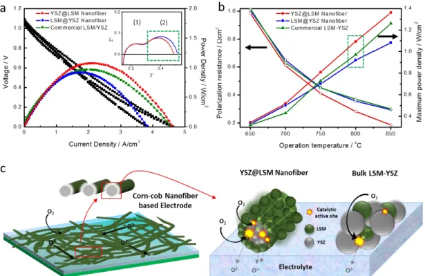
As shown in Figure 6, these great improvements of the prepared corn-cob nanofiber catalysts were directly translated to the SOFC single cell tests to prove the possibility of using our new electrode structure to the real full cell system. Figure 6(a) demonstrates the
I-V curves (black line) at 800 oC for the nanofibrous cathodes that are
fabricated by YSZ@LSM and LSM@YSZ nanofibers, including the commercial LSM-YSZ. The results displayed typical I-V curve shapes with similar open circuit voltages of 1.09 V. This reveals that the prepared cells showed a good reproducability by a uniform dense electrolytes (Figure S4) and good sealing in the test apparatus. Therefore, we could focus on only the effect of the corn-cob nanofibrorous structure and the position of LSM/YSZ at the core@shell. Comparing the SOFC single cell performances that was tranferred to the power density, the cathode by corn-cob nanofiber with LSM shell and YSZ core yielded the best maximum power density of 1.15 Wcm-2 at a current density of 2.08 Acm-2. This
enhanced outcome was highly improved compare to our previous works and the tested performance of the commercial LSM-YSZ
cathode with around 0.98 Wcm-2.12,20 Moreover, this achievement
was even higher compare to the electrode by the opposite configuration of LSM and YSZ with the maximum power density of
0.91 Wcm-2 at a current density of 1.79 Acm-2. It was found that the
trend of the maximum power densities and resistances were consistent with the half-cell data for the corn-cob fibers and commercial cathode, as we discussed before (Figure 5). Therefore, as the same material compositions and single cell structure are the same for both electrodes, we can clearly see that the difference in performance may come from the nanofibrous structure and also the effective ORR mechanism when LSM is at the shell and YSZ at the core position.
To investigate this more in detail, the polarization resistances of both YSZ@LSM and LSM@YSZ nanofiber cathodes were measured as in the inset of Figure 6(a). Two depressed arcs were observed at the tested temperature of 800 oC. The total resistance for the nanofiber with LSM shell and YSZ core was smaller than the upside one with the value of 0.309 Ω (vs. 0.359 Ω), which is much smaller
than of other previous works.12,20 Generally, the first arc (1) can be
assigned to the charge transfer process and the second arc (2) provides an information about the dissociation of oxygen molecules
and adsorption of oxygen gas into the cathode.21,27,38-39 Based on the
same material compositions, there was no big difference in the intrinsic property of the cathode. However, it was interesting that the lower total resistance of the YSZ@LSM nanofibrous cathode came from the slightly smaller second arc (2) than the LSM@YSZ nanofiber based cathode, indicating that the YSZ@LSM structure poseess more active sites for the dissociation of oxygen molecules and adsorption of oxygen gas. At the same time, it implies a better ORR activity of the cathode when the LSM is located at the outside. Remarkably, this tendancy was even more obvious at elevated temperatures. Figure 6(b) elucidates the summary of the polarization resistances and maximum power densities in terms of
different operation temperatures by varying from 650 oC to 850 oC.
As shown in Figure 6S, the characteristic frequencies shifted to a high-frequency regime as the operating temperature increased accordingly with the half-cell results, because the catalytic activity is generally accelerated at higher temperature. The resistance difference between two corn-cob nanofiber based cathodes became wider, which strongly influences to the higher performance for the YSZ@LSM nanofibrous cathode and even higher than the commercial LSM-YSZ cathode.
Table 1. Thickness, BET surface area, total pore volume and average pore diameter for the cathodes by the YSZ@LSM and LSM@YSZ nanofibers, comparing to the LSM-YSZ commercial.
Cathode thickness (µm)
BET Surface
Area (m2 g-1)
Total pore volume (cm3 g-1)
Average pore diameter
(nm) YSZ@LSM
Nanofiber 15.2 1.95 0.579 1180
LSM@YSZ
Nanofiber 14.9 1.87 0.595 1271
Commercial
Please do not adjust margins
The illustrations in Figure 6(c) explained the reasons for the enhanced catalytic properties of the YSZ@LSM nanofiber based
cathode comparing also to the normally mixed LSM and YSZ cathode. The first reason is the unique porous network that is offered from the stacked nanofibrous web, as displayed at the left hand side in Figure 6(c). This nanofibrous microstructure provides a large surface-to-volume ratio from more and larger pores, which favors improved catalytic activity by a better mass/gas diffusions in the cathode. Also, the nanofibers are composed of connected LSM and YSZ whereas the commercial LSM-YSZ powder is not percolated due to the absence of the continuous charge transfer. These continuous nanofibers transferred electrons and oxygen ions, respectively, better to the whole electrode with less
interruption.27,31-32 Furthermore, from the formation of unique
microstructure structure by a nanofibrous web, higher surface area of the architected nanostructure was created, which is greatly related to the large number of active reaction sites.
The right hand side of Figure 6(c) illustrated the expected mechanisms of the YSZ@LSM nanofiber and LSM/YSZ mixture on the electrolyte as cathodes. Higher performance based on the same cell composition may come from the better ORR activity, which is normally taken place at the TPB interface of oxygen gas, LSM and YSZ with the order of reactant transfer, catalytic reaction and charge transfer.20-24,32-34 From this mechanism, it is clear for YSZ@LSM nanofibrous cathode that the improved microstructure provides oxygen adsorbed easily to the LSM. Furthermore, more number of active sites could be formed for LSM positioned at outside to catalytically react. On the other hand, the nanofiber with
the YSZ shell and LSM core may produce less active sites since the YSZ shell interrupt to reach the oxygen to react with the LSM
catalyst. The nanofibrous microstructure with YSZ core and LSM shell were even more effective compare to the LSM/YSZ mixture due to its smaller amount of active sites from the randomly distributed structure of each materials and lower surface area from the clogged pore structure. Therefore, we could find out that the expected mechanism suggests direct evidences of the advantages for electrode design by the corn-cob nanofibers with LSM shell and YSZ core. Overall for the new cathode microstructure design through YSZ@LSM nanofibers, all these reasons result in better catalytic activity for the oxygen reduction reaction and decrease the polarization resistance at the same time, which are anticipated to reveal a high SOFC efficiency at the single cell operation.
4. Conclusions
Here, we designed a new nanofibrous microstructure by utilizing LSM/YSZ corn-cob nanofibers for an efficient SOFC operation. The preparation of unique corn-con ceramic nanofibers were introduced by the means of one-step electrospinning with a dual nozzle. We found that a core-shell like structure with a nanoparticles outside can be obtained from the different weight ratio of the precursors for immiscible core-shell structure. The uniform diameter of the fibers were achieved and resulted in the feature of corn-cob. The nanofiber with LSM shell and YSZ core
(YSZ@LSM) reveals a SOFC single cell performance of 1.15 Wcm-2
that is higher than the commercial LSM-YSZ based cathode.
6 | J. Name., 2012, 00, 1-3 This journal is © The Royal Society of Chemistry 20xx
Figure 6. (a) Single cell performance from the plot of I-V (inset: impedance results) and power density at 800 oC and (b) polarization
resistance vs. maximum power density according to the operation temperatures of 650 o
C to 850 o
Furthermore, when the shell and core were changed, we observed a different behavior. The YSZ@LSM nanofiber shows lower resistance than the opposite one (LSM@YSZ nanofiber), even at the increased temperature where the oxygen adsorption and surface reaction are more active by larger catalytic active sites. This is directly conveyed to the higher single cell performance, provides us useful and meaningful results, especially, to the field of high temperature SOFC. Therefore, we can highlight a critical role of the electrode microstructure design by the nanofibrous corn-cob structure and the position of LSM-YSZ at the core@shell structure, which has not been rigorously controlled to date for an effective SOFC cathode.
5. Acknowledgements
This research was supported by the New & Renewable Energy Core Technology Program of the Korea Institute of Energy Technology Evaluation and Planning (KETEP) with a financial resource from the Ministry of Trade, Industry & Energy (No. 20133030011320).
6. Notes and references
1 M. Z. Jacobson, Energy Environ. Sci., 2009, 2, 148–173.
2 M. K. Debe, Nature 2012, 486, 43–51.
3 Z. Chen, D. Higgins, A. Yu, L. Zhang, J. Zhang, Energy Environ.
Sci., 2011, 4, 3167–3192.
4 Y. Jeon, D. Kim, J. Koh, Y. Ji, J. Kim, Y. Shul, Sci. Rep. 2015, 5,
1–11.
5 N. Mahato, A. Banerjee, A. Gupta, S. Omar, K. Balani,
Progress in Materials Science. 2015, 72, 141–337.
6 Z. Shao, S. M. Haile, Nature 2004, 431, 170–173.
7 S. Tao, J.T.S. Irvine, Nat. mater. 2003, 2, 320–323.
8 A. Yaqub, C. Savaniu, N. K. Janju, J. T. S. Irvine, J. Mater. Chem. A, 2013, 1, 14189–14197.
9 T. Kenjo, M. Nishiya, Solid State Ionics 1992, 57, 295-302.
10 K. Sasaki, L.J. Gauckler, In Proc. Int. Symp. Struct. Func. Grad.
Mater. 1995, 3, 651–664.
11 M. Juhl, S. Primdahl, C. Manon, M. Mogensen, J. Power
Sources 1996, 61, 173–181.
12 H. S. Song, S. Lee, S. H. Hyun, J. Kim, J. Moon, J Power Sources 2009, 187, 25–31.
13 S. B. Adler, Chem. Rev., 2004, 104, 4791–4844.
14 Z. Gao, L. V. Mogni, E. C. Miller, J. G. Railsback, S. A. Barnett, Energy Environ. Sci., 2016, in press.
15 Y. Chen, L. Yang, F. Ren, K. An, Sci. Rep. 2014, 4, 5179.
16 Y. Chen, W. Zhou, D. Ding, M. Liu, F. Ciucci, M. Tade, Z. Shao, Adv. Energ. Mater., 2015, 5, 1500537.
17 H. Ko, J. Myung, S. Hyun, J. Chung, J Appl. Electrochem.
2012, 42, 209–215.
18 J. M. Vohs, R. J. Gorte, Adv. Mater. 2009, 21, 943–956.
19 D. Ding, X. Li, S. Y. Lai, K. Gerdesb, M. Liu, Energy Environ.
Sci. 2014, 7, 552–575.
20 J. Myung, H. J. Ko, H. Park, M. Hwan, S. H. Hyun, Int J
Hydrogen Energy 2012, 37, 498–504.
21 J. S. Croninz, K. Muangnapoh, Z. Patterson, K. J.
Yakal-Kremski, V. P. Dravid, S. A. Barnett, J Electrochem. Soc., 2012,
159, B385–B393.
22 J. R. Wilson, W. Kobsiriphat, R. Mendoza, H. Chen, J. M. Hiller, D. J. Miller, K. Thornton, P. W. Voorhees, S. B. Adler, S.
A. Barnett, Nat. Mater. 2006, 5, 541–544.
23 P. Boldrin, E. Ruiz-Trejo, J. Yu, R. I. Gruar, C. J. Tighe, K.
Chang, J. Ilavsky, J. A. Darrc, N. Brandon, J. Mater. Chem.
A, 2015, 3, 3011–3018.
24 X. Zhang, L. Liu, Z. Zhao, B. Tu, D. Ou, D. Cui, X. Wei, X. Chen,
M. Cheng, Nano Lett., 2015, 15, 1703–1709.
25 J. Choi, C. Lee, S. C. Hawkins, C. P. Huynh, J. Park, Y. Jeon, Y.
B. Truong, I. L. Kyratzis, Y. Shul, R. A. Caruso, RSC Adv., 2014,
4, 32787–32790.
26 M. Zhi, G. Zhou, Z. Hong, J. Wang, R. Gemmen, K. Gerdes, A.
Manivannan, D. Mae, N. Wu, Energy Environ. Sci., 2011, 4,
139–144.
27 M. Zhi, S. Lee, N. Miller, N. H. Menzlerd, N. Wu, Energy Environ. Sci., 2012, 5, 7066–7071.
28 J. Lee, C. Lee, M. Park, Y. Shul, RSC Adv. 2013, 3, 11816–
11822.
29 Y. Dai, W. Liu, E. Formo, Y. Sun, Y. Xia, Polym. Adv. Technol.
2011, 22, 326–338.
30 C. Lee, Y. Jeon, S. Hata, J. Park, R. Akiyoshi, H. Saito, Y.
Teraoka, Y. Shul, Appl. Catal. B: Environ. 2016, 191, 157–164.
31 J. Lee, J. Park, Y. Shul, Nat. Comm. 2014, 5, 4045.
32 M. Zhi, N. Mariani, R. Gemmen, K. Gerdes, N. Wu, Energy
Environ. Sci., 2011, 4, 417–420.
33 S. Lee, H. Song, S. Hyun, J. Kim, J. Moon, J Power Sources
2010, 195, 118–123.
34 J. Kim, N. L. Wieder, A. J. Abraham, M. Cargnello, P.
Fornasiero, R. J. Gorte, J. M. Vohs, J. Electrochem. Soc. 2011
158, B596–B600.
35 R. Khajavia, M. Abbasipour, Scientia Iranica, 2012, 19, 2029–
2034.
36 M. F. Elahi, W. Lu, G. Guoping, F. Khan, J Bioengineer & Biomedical Sci, 2013, 3, 121.
37 C. Korte, A. Peters, J. Janek, D. Hesse, N. Zakharov, Phys.
Chem. Chem. Phys., 2008, 10, 4623–4635.
38 J. Nielsen, J. Hjelm, Electrochim. Acta, 2014, 115, 31–45.
39 S. W. Lee, N. Miller, M. Staruch, K. Gerdes, M. Jain, A.