R E S E A R C H
Open Access
Multi-target simultaneous ISAR imaging
based on compressed sensing
Gang Li
*, Qingkai Hou, Shiyou Xu and Zengping Chen
Abstract
Conventional range-Doppler (RD) inverse synthetic aperture radar (ISAR) imaging method utilizes coherent integration of consecutive pulses to achieve high cross-range resolution. It requires the radar to keep track of the target during coherent processing intervals (CPI). This restricts the radar’s multi-target imaging ability, especially when the targets appear simultaneously in different observing scenes. To solve this problem, this paper proposes a multi-target ISAR imaging method for phased-array radar (PAR) based on compressed sensing (CS). This method explores and exploits the agility of PAR without changing its structure. Firstly, the transmitted pulses are allocated randomly to different targets, and the ISAR image of each target can be then reconstructed from limited echoes using CS algorithm. A pulse allocation scheme is proposed based on the analysis of the target’s size and rotation velocity, which can guarantee that every target gets enough pulses for effective CS imaging. Self-adaptive mechanism is utilized to improve the robustness of the pulse allocation method. Simulation results are presented to demonstrate the validity and feasibility of the proposed approach.
1 Introduction
Inverse synthetic aperture radar (ISAR) can generate im-ages of targets with high resolution in two dimensions. It usually transmits wideband waveform to obtain high-range resolution and utilizes coherent integration of multi-pulse to achieve high cross-range resolution [1]. This is the basic idea of range-Doppler (RD) imaging. It requires both appropriate rotation angle (usually 3°–5° for RD imaging) and consecutive pulses during coherent processing intervals (CPI) [2].
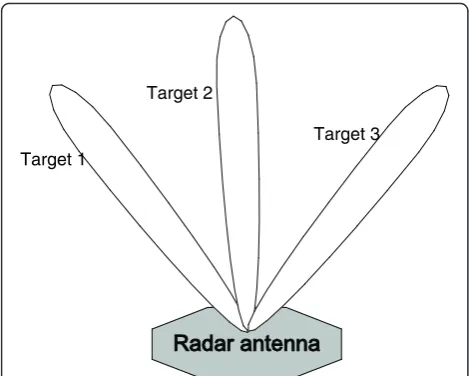
To the best of our knowledge, most ISARs in practice can only generate images one target at a time. Since the RD imaging method requires consecutive echoes, the radar must track the target for a long period. The ob-serving scene of radar is always a limited region defined by the radar’s receiving range gate and the beam width. Therefore, the observing scene of ISAR must be focused on the target during the CPI. In some applications, the radar needs to observe several targets appearing in dif-ferent observing scenes simultaneously, as shown in Fig. 1. Such scenes are quite common for military air defense radars or space surveillance radars. Modern PAR
with active electronically scanning phased-array antenna can change the frequency and beam direction of signal between pulses readily [3]. Therefore, PARs are widely applied in multi-target radars, such as long-range air defense radars and missile-tracking radars.
Although PAR can achieve multi-target detection and tracking comfortably by allocating the pulses to each target, there are still some challenges in imaging them simultaneously. As is well known, the maximum pulse repetition frequency (PRF) of radar is limited by the ob-serving distance to prevent range ambiguity. Meanwhile, the radar still needs to assign some pulses for target de-tection, tracking, and other functions [4]. Hence, the
PAR’s pulses may be inadequate for the coherent
inte-gration of each target. This paper aims to exploit the flexibility of PAR and to achieve better performance in multi-target imaging.
Recently, CS has drawn great attention in data acquisi-tion and signal processing. It suggests that the signal can be sampled at sub-Nyquist rate and be reconstructed correctly if the signal is sparse or compressive in some
basis or transform domain [5–9]. ISAR imaging based
on CS is also an active research area since the targets often show sparse reflections and occupy only limited pixels in the imaging results [10, 11]. It has been pro-posed in [12] that ISAR image can be reconstructed * Correspondence:[email protected]
College of Electronic Science and Engineering, National University of Defense Technology, Changsha, Hunan 410073, China
using much fewer pulses than RD algorithm with ran-dom pulse repetition interval (PRI). At present, most of the research on CS imaging is aimed at a single target and has achieved some research results [7–10, 12]. Con-sidering the requirement of radar multi-target observa-tion and imaging, this paper tries to use the CS imaging method to improve the ability of simultaneous multi-target radar imaging.
Inspired by CS and the flexibility of PAR, we allocate the pulses randomly to multiple targets appearing in different observing scenes. The radar illuminates one target at one pulse and changes target from pulse to pulse. The observing sequence is arranged randomly to realize non-uniform sampling in the cross-range di-mensions of each target. Such random sampling can insure that the measurement matrix satisfies the re-stricted isometry property (RIP), which is the sufficient criterion for effective reconstruction in CS [13, 14]. An-other major contribution of this paper is that we propose a pulse allocating strategy based on detailed analysis of CS ISAR imaging. Besides random sampling, the sizes and rotation velocities of targets are also de-termining factors for pulse allocation. This allocation of pulse guarantees that every target obtains enough mea-surements for effective CS reconstruction. The key innovation of this method is fully utilizing the limited resource of radar pulses to implement multi-target im-aging, based on the image sparsity and CS algorithms. After random observation, the measurement matrices for the targets are different from each other; thus, the images are reconstructed separately using CS algo-rithms. Experiment results are provided to demonstrate the validity of this observing strategy and imaging method.
This paper is organized as follows. In Section 2, the mathematic model of ISAR imaging is built and the CS imaging method is presented. In Section 3, the multi-target observing scheme and reconstructing method of ISAR image are presented based on CS. The experiment results and analysis are provided in Section 4, and con-clusions are given in Section 5.
2 CS ISAR imaging using limited pulses
2.1 Model of range-Doppler ISAR imaging
Assume that the translational motion of the target has been compensated using conventional methods [15–17]. The target can be treated as a platform
which rotates around the center O, as shown in Fig. 2.
Suppose the transmitted linear frequency modulation (LFM) signal is
STð Þ ¼t rect t
TP
exp j2π fctþ
1 2γt
2
ð1Þ
where rectð Þ ¼u 10;; j ju≤1=2 u
j j>1=2
,fcrepresents the
cen-ter frequency,Tp is the pulse width, γ is he frequency modulation rate, and t is the fast time. The echo reflected by the scattering point locating at P(x, y) after matched filtering pulse compression can be written as
sRðt;tsÞ ¼βsinc Tpγ t−2R tð Þs c
exp −j4πR tð Þλs
ð2Þ whereβis the backward scattering intensity ofP(x,y), λ is the wavelength of signal, t is the fast time, and ts is the slow time. R(ts) is the instantaneous distance from P(x,y) to radar and atts
R tsð Þ ¼R0þycosθð Þ þts xsinθð Þts ð3Þ
Target 1
Target 2
Target 3
Fig. 1Scenario of multi-target for PAR ISAR radar
Location 0
(
,
)
P x y
( )
t
sq
X
0
R
Radar
O
s t
P
where θ(ts) is the instantaneous rotation angle of the mth pulse. Since the rotation angle is usually very small in ISAR, theR(ts) can be approximated as
R tsð Þ≈R0þyþxθð Þts ð4Þ
In Eq. (4), θ(ts) can be approximated by Taylor expan-sion as
θð Þts ≈ωtsþ0:5αt2s þσ t2s ð5Þ where ω and α are rotation velocity and acceleration, respectively. Therefore, the echo can be approximated as
sRðt;tsÞ≈βsinc TPγ t−
Suppose the total number of range cells isMand there
areKscatters in themth range cell. The rotational mo-tion is assumed to be stamo-tionary. After neglecting the constant term and high-order term, the signal of the
mth range cell can be denoted as
smð Þts ≈ which denotes the kth scattering point’s intensity. In RD imaging, the cross-range compression is achieved by ap-plying a Fourier transform in the cross-range dimension. Let fk¼2xλkω denote the Doppler frequency of the kth
scatter, and we can achieve the compression result of the mth range cell as
Considering the sampling window in the cross-range domain, theδ(•) function will be substituted by sinc(•).
If we build a dictionaryΨ and theith column ofΨis ψi= exp[−j2πfd(i)ts], Eq. (7) can be rewritten in the
matrix form as
sm¼Ψβmþn ð9Þ
where sm is the vector form of sm(ts), βm is the vector which denotes the scatters distribution in themth range cell, and n is the measuring noise. The whole image of the target is obtained after cross-range compression of allMrange cells.
2.2 CS ISAR imaging using random pulses
In most ISAR cases, there are only a few strong ing points in one range cell, and the number of scatter-ing centers is much smaller than the number of pulses.
Therefore, the vector β is sparse, and the echoes of
target are compressive in the cross-range dimension. CS ISAR imaging method has been proposed in [12] to re-construct the image using much fewer pulses than RD algorithm with random PRI. In this paper, further study about CS ISAR imaging is carried on and some condi-tions are given for effective CS imaging.
First, to achieve effective reconstruction in CS, the number of measurements must exceed the theoretical minimal number [6].
M>O Kð ⋅logNÞ ð10Þ where K is the sparse level and N is the length of the measured sparse signal. In the context of CS ISAR im-aging, the sparse level K is the number of cross-range bins which are occupied by target in image, and Eq. (10) determines the minimal number of transmitted pulses for the target.
Second, the cross-range resolution in conventional RD imaging is defined by the wavelength of transmitted sig-nalλand the target’s rotational angle Θduring the CPI, which is denoted as
Δc¼ λ
2Θ ð11Þ
The rotation angle Θ is usually 3°–5° because the
smaller angle is inadequate for high resolution and the migration through resolution cell (MTRC) will occur if
Θ is larger [18]. Moreover, the sampling rate in the
imaging, since the random pulses are the subset of Nyquist-sampled pulses in RD imaging, Eq. (11) still de-termines the cross-range resolution, and enough rotation angle is also required for high resolution.
According to the above analysis, we give the following two conditions that the random measurements must sat-isfy to achieve effective CS ISAR imaging.
2.2.0.1 Condition 1. The number of random pulses M
is more than the minimal measurements needed by CS, as (10).
2.2.0.2 Condition 2. The rotation angle of the target during CPI is approximately 3°-5°, which is the same as RD method. This guarantees the reconstructed image own the same cross-range resolution as RD imaging result.
3 CS multi-target simultaneous imaging
3.1 Basic idea of multi-target observation
Based on the CS ISAR imaging, a multi-target imaging method is proposed for PAR in this section. As intro-duced in Section 1, there may be multiple targets in dif-ferent observing scenes, but the radar can only observe one target at one pulse. Instead of illuminating one tar-get during the whole CPI, the pulses can be allocated to all the targets and the observing sequence is arranged randomly. Therefore, the PRI for each target is non-uniform and the measurements of every target are ran-dom sampling, which coincides with the CS imaging method condition for single target in [12].
Suppose there are four different targets, and Fig. 3 shows the sequence of transmitted pulses, which are al-located randomly. As a simple example, the pulses are allocated to four targets with equal proportion in Fig. 3, e.g., the probability of being illuminated for each target is equal. However, such an equal proportion is appar-ently too simple for the practical applications. The em-phasis of this section is to determine the allocating proportions of pulses for different targets.
In the train of transmitted pulses, the illuminated target of each pulse can be treated as an independent
and identically distributed (I.I.D.) random variable A.
A∈{0, 1, 2⋯L}, where L is the number of targets.
Am=i(0 <i≤L) means the mth pulse illuminates the
ith target, while Am= 0 means no target is observed,
e.g., this pulse is not used in any target’s imaging.
The probability distribution of A determines the
allo-cation proportions of pulses for different targets. To obtain effective CS measurements for each tar-get, random allocation of pulses must ensure that the measurements of every target satisfy the two condi-tions presented in Section 2. Based on this, we
propose an algorithm to determine the probability distribution of A.
For condition 1, the key problem is to determine the sparse level of target, namely the size of target in cross-range dimension. For coarse estimation, the tar-get’s size can be estimated from the radar cross-section (RCS) [20] and high-resolution range profiles (HRRPs) of the targets. Although these methods can-not provide accurate estimation of the cross-range size of target, they can help to determine the sparse level of target roughly. Together with the expected resolution of ISAR image Δc, the sparse level of target
ki can be estimated by
Ki¼Di=Δc ð12Þ
where Di is the estimated size of target. Therefore, the number of pulses Mi needed for each target can be cal-culated in Eq. (10).
As for condition 2, the CPI of a target depends on
its rotation velocity ω with respect to the radar line
of sight. For space objects, the rotation velocity ω can
be estimated from the orbit information. While for
other non-cooperate targets, the ω can be estimated
from Doppler analysis of target’s echoes. Reference
[21] suggests that the received signal of range bin can be approximated as cubic phase signals, and the ratio of the third-order phase coefficient to the first-order phase coefficient is just the square of the rotation vel-ocity. We use this algorithm to estimate the rotation
velocity ωi of each target, and the CPI τi of target
can be obtained by
τi¼
Θ
ωi ð
13Þ where Θ is the typical rotation angle for ISAR imaging and is set to beΘ ¼4°.
Based on those estimations, the least number of pulses and CPIs of each target are determined. We useρito de-note the equivalent average PRF for theith target, andρi is given as
ρi¼Mi
τi ð
14Þ
It proposes that the allocating probability for different target is proportional to the equivalent average PRFρiof each target. The probability distribution ofAmfollows
P Að m¼iÞ ¼
ρi
fPRF
Prior measurement for each target after detection
Estimate the size Diand rotation velocity
iof each target
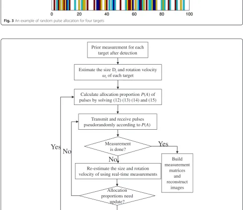
Calculate allocation proportion P(A) of pulses by solving (12) (13) (14) and (15)
Transmit and receive pulses pseudorandomly according to P(A)
Measurement is done?
Re-estimate the size and rotation velocity of using real-time measurements
Allocation proportions need
update?
Build measurement
matrices and reconstruct
images
Yes
Yes
No
No
Fig. 4Flow chart of compressive measurement for multiple targets
Cross-Range/m
m/
e
g
n
a
R
-30 -20 -10 0 10 20 30
1.997 1.998 1.999 2 2.001 2.002 2.003x 10
4
Cross-Range/m
m/
e
g
n
a
R
-30 -20 -10 0 10 20 30
1.997 1.998 1.999 2 2.001 2.002 2.003x 10
4
a
b
Cross-Range/m
m/
e
g
n
a
R
-30 -20 -10 0 10 20 30
1.997 1.998 1.999 2 2.001 2.002 2.003x 10
4
Cross-Range/m
m/
e
g
n
a
R
-30 -20 -10 0 10 20 30
1.997 1.998 1.999 2 2.001 2.002 2.003x 10
4
c
d
Cross-Range/m
m/
e
g
n
a
R
-30 -20 -10 0 10 20 30
1.997 1.998 1.999 2 2.001 2.002 2.003x 10
4
Cross-Range/m
m/
e
g
n
a
R
-30 -20 -10 0 10 20 30
1.997 1.998 1.999 2 2.001 2.002 2.003x 10
4
e
f
XL
i¼1
ρi≤fPRF ð16Þ
If targets number L exceeds this limitation, the pulse
allocation cannot guarantee that enough measurements are acquired for each target.
For the convenience of radar management, the estima-tion of sparse level and rotaestima-tion velocity can be obtained as prior information for multi-target CS imaging. Specif-ically, this can be done after the radar detection and tracking process; then, the wideband pulses for imaging are transmitted pseudo-randomly according to the esti-mated probability densityP(Am).
3.2 Adaptive pulse allocating method
The estimations of rotation velocity and target size are very important for the multi-target CS imaging method. However, the estimation results in practice are usually inaccurate due to the influence of noise and clutters. Be-sides, the prior measurements before imaging may be in-sufficient or incorrect to determine the appropriate pulse allocating proportions. Considering this, an im-proved adaptive observing strategy for multiple targets is introduced in this section. With the development of digital processing, the modern radar systems can own more powerful real-time processing ability. During CS imaging, some real-time analysis can be carried out to estimate the velocities and sizes of the targets. This al-lows us to update the allocating proportions of pulses during observation.
In three situations, we need to re-calculate the allocat-ing proportions for different targets. (1) Some targets disappear from the radar’s view and do not need imaging anymore; then, it is eliminated from the targets list. (2) A new target is detected and is added into the imaged targets list. (3) The estimations of targets’velocities and sizes are considerably different from the current ones.
The self-adapting allocation proportions can improve the robustness of the multi-target observing method. For convenience of understanding, a flow chart is presented to interpret the work mode of radar in the adaptive CS imaging method, as shown in Fig. 4.
The sequence of pulses must be memorized in the radar system because it is essential to build the measure-ment matrices of each target, which will be discussed in Section 3.3.
Limited by the real-time capability of the radar system and the complexity of CS reconstructing algorithms, it is difficult to realize real-time image reconstruction using limited pulses. Once it is solved with faster algorithms, the iterative method can be employed in the flow of multi-target observation. Instead of estimating the sizes and velocities of targets based on the RCS and HRRPs,
the quality of real-time imaging results can be employed to evaluate whether the pulse allocation proportion is ef-fective. In the following observation, more pulses will be allocated to those targets with blurred images. The most reasonable proportions will be established after several iterations. This is the unsolved issue that we are investi-gating in the future work.
3.3 Reconstruction images of multiple targets
In ISAR imaging, the non-cooperative motion of target must be compensated to make the echoes consistent with the model of rotated platform in Fig. 2. References [22] and [23] suggest the method that minimizes entropy of average range profile, and the eigenvector method can be utilized to solve the range alignment and phase cor-rection of random pulses. Reference [24] proposed a method to solve the problem of motion compensation when pulses are inconsecutive. Combining Eq. (9), the echoes after compensation can be denoted as
ym¼ΦΨβmþn ð17Þ
where matrixΦis the random measurement matrix, and vectors ym and n are the measurements of mth range cell and the measured noise, respectively. The cross-range image βmof mth range cell can be reconstructed by solving
min β^m
1 s:t: kym−ΦΨβk2≤ε ð18Þ where ^βm is the reconstruction of vectorβand ε is the noise level. It is the typical optimization problem in CS and there are some algorithms to solve it, such as basis pursuit (BP), orthogonal matching pursuit (OMP), Bayesian algorithms [25], and smoothed ℓ0 algorithm (SL0). The SL0 [26] has a good tradeoff between accur-acy and complexity [27]. Different from most greedy al-gorithms and BP alal-gorithms, the sparsity level of an original signal is not necessary for SL0 method. There-fore, it is quite suitable for CS radar imaging, since the number of scattering centers is unknown until the image is obtained.
The first step of reconstructing multi-target images is to build the measurement matrices for each target. In conventional Nyquist sampling, the measurement matrix is the identity matrix Ii, and the size Ni of matrix Ii is
Table 1Parameter setting of three targets in simulation
Target Range (km) Rotation velocity 1 (°/s) Rotation velocity 2 (°/s)
Target 1 100 2.0 1.0
Target 2 120 2.0 2.5
Cross-Range/m
m/
e
g
n
a
R
-30 -20 -10 0 10 20 30
1.997 1.998 1.999 2 2.001 2.002 2.003x 10
4
Cross-Range/m
m/
e
g
n
a
R
-30 -20 -10 0 10 20 30
1.997 1.998 1.999 2 2.001 2.002 2.003x 10
4
a
b
Cross-Range/m
m/
e
g
n
a
R
-30 -20 -10 0 10 20 30
1.997 1.998 1.999 2 2.001 2.002 2.003x 10
4
Cross-Range/m
m/
e
g
n
a
R
-30 -20 -10 0 10 20 30
1.997 1.998 1.999 2 2.001 2.002 2.003x 10
4
c
d
Cross-Range/m
m/
e
g
n
a
R
-30 -20 -10 0 10 20 30
1.997 1.998 1.999 2 2.001 2.002 2.003x 10
4
Cross-Range/m
m/
e
g
n
a
R
-30 -20 -10 0 10 20 30
1.997 1.998 1.999 2 2.001 2.002 2.003x 10
4
e
f
Cross-Range/m
m/
e
g
n
a
R
-30 -20 -10 0 10 20 30
1.997 1.998 1.999 2 2.001 2.002 2.003x 10
4
Cross-Range/m
m/
e
g
n
a
R
-30 -20 -10 0 10 20 30
1.997 1.998 1.999 2 2.001 2.002 2.003x 10
4
a
b
Cross-Range/m
m/
e
g
n
a
R
-30 -20 -10 0 10 20 30
1.997 1.998 1.999 2 2.001 2.002 2.003x 10
4
Cross-Range/m
m/
e
g
n
a
R
-30 -20 -10 0 10 20 30
1.997 1.998 1.999 2 2.001 2.002 2.003x 10
4
c
d
Cross-Range/m
m/
e
g
n
a
R
-30 -20 -10 0 10 20 30
1.997 1.998 1.999 2 2.001 2.002 2.003x 10
4
Cross-Range/m
m/
e
g
n
a
R
-30 -20 -10 0 10 20 30
1.997 1.998 1.999 2 2.001 2.002 2.003x 10
4
e
f
the number of pulses transmitted during corresponding CPIτi, and
Ni¼fPRFτi ð19Þ
In CS multi-target imaging, the pulses are randomly allocated in CPI for each target. Hence, the measure-ment matrixΦiof theith target’s echo in Eq. (17) can be
obtained by selecting corresponding rows from Ii
ac-cording to the random sequence of pulses. The selected indices of rows are determined by the indices of the pulses that illuminate theith target.
Then, the images can be reconstructed by solving Eq. (18) for each target separately. The reconstructing performance and analysis will be given in Section 4.
4 Simulation results
To verify the validity of the proposed observing strategy and imaging method, some simulations are performed in this section. Suppose the parameters of the transmitted
LFM signal are as follows. The bandwidth isB= 300 MHz,
the carrier frequency is fc= 10 GHz, the pulse width
is τc= 50 μs, and the PRF of radar is fPRF= 1000 Hz.
In the simulation, three aeroplanes with different sizes are selected as the targets, which locate in different ob-serving scenes. The point scattering models of the three targets are given in Fig. 5. The parameters of the three targets are presented in Table 1. As shown in Fig. 5, the sizes of three targets are different, and the sparse level
Ki of target is determined by the number of scattering
points in the cross-range dimension. The simulations are carried out in two steps.
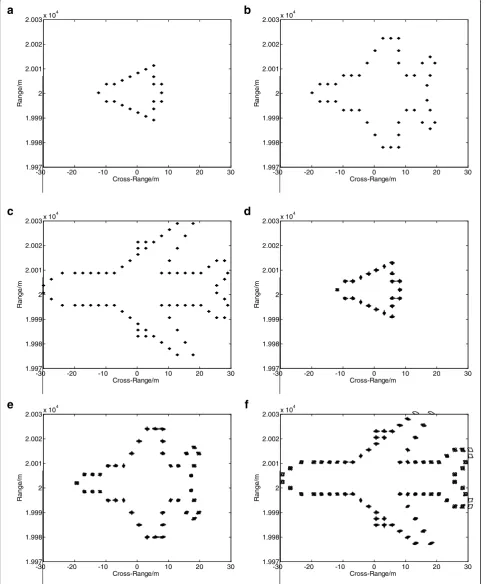
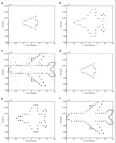
In the first experiment, the simulation is carried out to testify the effectiveness of target sizes on the allocation proportions of pulses. The rotation velocities of three targets are set to be the same, as shown in the third col-umn of Table 1. If we allocate the radar pulses equally, without considering the difference of target sizes, the re-constructed images of three targets are shown in Fig. 6a–c. As we can see, target 3 has the biggest size, and the corresponding reconstructed image is blurred seriously. However, the images of the other two targets are well focused. Then, we use Eq. (15) to calculate the allocating proportions for three targets, and the propor-tion is about 2:3:4. As shown in Fig. 6d–f, all targets are allocated with enough pulses, and thus, the images are all well focused.
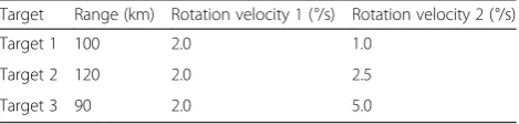
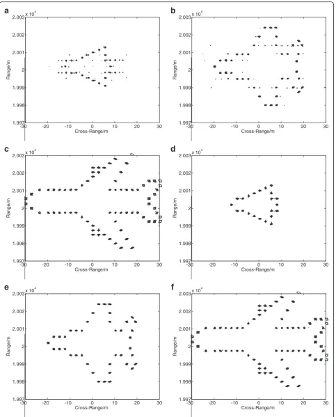
In the second experiment, the difference of rotation velocities is considered and the rotation velocities of the three targets are set as the fourth column of Table 1. The CPIs of three targets can be calculated to be about τ1= 5.0 s, τ2= 2 s, andτ3= 1 s, respectively. First, the
al-locating probability is calculated by Eq. (15) without considering the difference of rotation velocities. As
shown in Fig. 7a–c, the reconstructed images of targets 1 and 2 are blurred. The reason is that the two targets rotate much faster than target 3 and the allocated pulses are inadequate in their CPIs. Fig. 7d–f shows the recon-structed images when the allocating proportions of pulses are calculated according to both sizes and rota-tion velocities of three targets. Images with better quality are obtained for all targets.
The results of the simulations and comparison are consistent with the theoretical analysis in this paper. Hence, the proposed multi-target imaging method is proved to be reasonable and effective.
5 Conclusions
In order to implement multi-target simultaneous ISAR imaging, an observing strategy and CS imaging method is proposed in this paper. The CS theory is introduced into multi-target imaging, and a random pulse allocating method is proposed based on the flexibility of PAR. Multi-target simultaneous imaging is realized by control-ling the beam directions of radar pulses, without chan-ging the architecture and working mode of PARs. The method can take full advantage of radar resources and obtain images for multiple targets using much less pulses than conventional RD method. Although every target gets very limited pulses, the sparsity of ISAR images and the theory of CS guarantee effective recon-struction of images. The allocation proportion is calcu-lated based on the sizes and rotation velocities of targets. A self-adapting observing flow is designed for practical radar applications, which improves the robust-ness of the proposed method. SL0 algorithm is employed to reconstruct images of targets from random pulses. The simulation results testify the conclusion in this paper and prove the feasibility of the proposed method.
Competing interests
The authors declare that they have no competing interests.
Acknowledgements
This work was supported by the National Natural Science Foundation of China (Grant Nos. 61471373).
Received: 24 September 2015 Accepted: 18 February 2016
References
1. C Ozdemir,Inverse Synthetic Aperture Radar Imaging With MATLAB Algorithms (John Wileyand Sons, INC, Hoboken, New Jersey, 2012)
2. F Zhou, X Bai, M Xing, Z Bao, Analysis of wide-angle radar imaging. IET Radar, Sonar and Navigation5(4), 449–457 (2011)
3. Pirkl M. and Holpp W.,From research to application: how phased array radars conquered the real world, 14th International Radar Symposium, pp.17-22, 2013 4. M Zatman., in Proceedings of IEEE Radar Conference. Radar resource
management for UESA( IEEE Radar Conference, Long Beach, California, 2002) 5. DL Donoho, Compressed sensing. IEEE Trans Inf Theory52(4), 1289–1306 (2006) 6. EJ Cand`es, J Romberg, T Tao, Robust uncertainty principles: exact signal
7. MA Herman, T Strohmer, High-resolution radar via compressed sensing. IEEE Trans Signal Process57, 2275–2284 (2009)
8. JHG Ender, On compressive sensing applied to radar. Signal Process 90, 1402–1414 (2010)
9. X Bai, F Zhou, M Xing, Z Bao, High-resolution radar imaging of air-targets from sparse azimuth data. IEEE Trans on Aerospace and Electronic Systems 48(2), 1643–1655 (2012)
10. MG Amin, F Ahmad, Compressive sensing for through-the-wall radar imaging. J Electronic Imaging22, 030901 (2013)
11. D Li, X Li, Y Cheng, Y Qin, H Wang, Radar coincidence imaging in the presence of target-motion-induced error. J Electronic Imaging 23, 023014 (2014)
12. L Zhang, M Xing, C-W Qiu, J Li, Z Bao, Achieving higher resolution ISAR imaging with limited pulses via compressed sampling. IEEE Geosci Remote Sens Lett6, 567–571 (2009)
13. JA Tropp, AC Gilbert, Signal recovery from random measurements via orthogonal matching pursuit. IEEE Trans Inf Theory53, 4655–4666 (2007) 14. EJ Candes, The restricted isometry property and its implications for
compressed sensing. C R Acad Sci Paris, Ser I346, 589–592 (2008) 15. J Wang, D Kasilingam, Global range alignment for ISAR. IEEE Trans Aerosp
Electron Syst39, 351–357 (2003)
16. Y Wang, H Ling, V Chen, ISAR motion compensation via adaptive joint time-frequency technique. IEEE Trans Aerosp Electron Syst
34, 670–677 (1998)
17. RP Perry, RC Dipietro, R Fante, in Proceedings of IEEE National Radar Conference. Coherent Integration With Range Migration Using Keystone Formatting(IEEE National Radar Conference, Boston, MA,2007)
18. M Xing, R Wu, J Lan, Z Bao, Migration through resolution cell compensation in ISAR imaging. IEEE Geosci Remote Sens Lett1, 141–144 (2004) 19. J Ender, in Proceedings of 14th International IEEE Radar Symposium.
A brief review of compressive sensing applied to radar. (IRS 2013, Dresden, Germany, 2013)
20. R Lambour, N Rajan, T Morgan, I Kupiec, E Stansbery, Assessment of orbital debris size estimation from radar cross-section measurements. Adv Space Res34(No. 5), 1013–1020 (2004). Space Debris
21. Y Wang, Y Jiang, A novel algorithm for estimating the rotation angle in isar imaging. IEEE Geosci Remote Sens Lett5, 608–609 (2008)
22. D Zhu, X Yu, Z Zhu, in Proceedings of 2011 IEEE CIE International Conference on Radar. Algorithms for compressed ISAR autofocusing. (2011 IEEE CIE International Conference on Radar,Chengdu,China, 2011) 23. D Zhu, L Wang, Y Yu, Q Tao, Z Zhu, Robust isar range alignment via
minimizing the entropy of the average range profile. IEEE Geosci Remote Sens Lett6, 204–208 (2009)
24. Q Hou, L Fan, S Su, Z Chen, Compensation of phase errors for compressed sensing based ISAR imagery using inadequate pulses. Progress In Electromagnetics Research M41, 125–138 (2015)
25. S Ji, Y Xue, L Carin, Bayesian compressive sensing. IEEE Transctions on Signal Processing56, 2346–2356 (2008)
26. GH Mohimani, M Babaie-Zadeh, C Jutten, A fast approach for overcomplete sparse decomposition based on smoothed l0 norm. IEEE Trans Signal Process57, 289–301 (2007)
27. J Liu, S Xu, X Gao, X Li, Compressive radar imaging methods based on fast smoothed l0 algorithm. 2012 International Workshop on Information and Electronics Engineering29, 2209–2213 (2012). Elsevier Ltd
Submit your manuscript to a
journal and benefi t from:
7 Convenient online submission
7 Rigorous peer review
7 Immediate publication on acceptance
7 Open access: articles freely available online
7 High visibility within the fi eld
7 Retaining the copyright to your article