R E V I E W
Open Access
Spectral-energy efficiency maximization
for wireless powered low-latency NOMA
systems with full-duplex relaying
Xianghua Liu
1and Jianlin Mo
2*Abstract
This paper investigates a wireless powered communication system, where a base station (BS) and relay first harvest energy from the power beacon and use it for data transmission. Using non-orthogonal multiple access (NOMA), the BS delivers the messages to two NOMA users via a full-duplex (FD) relay to realize low-latency communication. As two important metrics in fifth-generation communication systems, spectral and energy efficiency are jointly analyzed in this paper. Under quality of service (QoS) requirement of two NOMA users and power constraints at the BS and relay, beamforming and time allocation ratio are jointly optimized so as to maximize sum data rate and energy efficiency of system. The formulated problems are hard to be solved directly due to its non-concave objective and non-convex constraints. To tackle these, one-dimensional search and path-following-based algorithms are proposed, which can iteratively obtain improved objectives with convergence guaranteed. With fast convergence and insensitivity to problem size, the proposed algorithm can reach at least local optimum. Numerical results verify the advantages of the proposed algorithms and the superiority of the proposed scheme.
Keywords: Energy efficiency, Non-orthogonal multiple access (NOMA), Full-duplex (FD), Low latency, Energy harvesting
1 Introduction
Being a state of the art, the exponential increment of traffic volume in wireless networks poses a formidable challenge to the design of modern wireless communica-tion systems, which need to provide larger bandwidth, higher data rate, and lower communication delays. Non-orthogonal multiple access (NOMA) and full-duplex (FD) are recently recognized as two promising techniques to enlarge connections, improve spectral efficiency, bal-ance user fairness, and support diverse services for the fifth-generation (5G) wireless communication networks
[1, 2]. On the one hand, NOMA allows multiple users
to access the same resources(frequency/time/code) via superposition coding in the power domain and sepa-rates interfered users by utilizing successive interference cancellation (SIC). NOMA can reach a balance between
*Correspondence:[email protected]
2Department of Electronic Information and Automation, ABA Teachers University, Wenchuan, 623002, China
Full list of author information is available at the end of the article
network throughput and user fairness by appropriately allocating the transmit power at the base station to mul-tiple users according to their different channel conditions [3]. On the other hand, full-duplex technique enables the radios to simultaneously transmit and receive on the same frequency channel. Compared with conventional half-duplex (HD), FD mode can avoid processing delay so as to enhance spectral efficiency [4].
To take advantage of cooperative communication, many researchers combine cooperative communication with NOMA to further improve user fairness and communica-tion reliability [5–7]. In cooperative NOMA, the relays are divided into two categories, i.e., user relay and dedicated relay. In [5], the authors proposed a novel cooperative NOMA scheme to enhance system capacity and user reception reliability. In the proposed scheme, some users in good channel conditions are regarded as relays to help the transmission between users in poor channel condi-tions and the BS. In addition, [6] adopted the dedicated relay to assist the BS to communicate with the far user. Ding [5] and Kim and Lee [6] showed the superiority of the
proposed cooperative schemes by simulation. Different from [5] and [6], [7] investigated a scenario in which the BS communicates with two users with the help of a ded-icated relay. However, the above works about cooperative NOMA mainly focus on half-duplex relay, which can only transmit or receive message at one time. To some extent, HD relay could lead to a reduction of spectral efficiency due to its extra time for cooperation.
Among all full-duplex transmission, full-duplex relay-ing is a typical application scenario, which has attracted significant attention in academia and industry [8–11]. In general, FD relay techniques are divided into two types, namely decode-and-forward (DF) relay and amplify-and-forward (AF) relay [12–15]. Since the transmit antenna at the relay is much closer to its receive antenna, FD relay easily suffers from self-interference (SI), which is the main challenge of FD relaying systems [16, 17]. To guarantee the feasibility of full-duplex relaying systems, many efforts have been made to degrade loop interference [18,19]. Under the circumstances that self-interference is effectively suppressed, many literatures have paid much attention to full-duplex relay-assisted cooperative NOMA systems [20–22]. Zhong and Zhang [20] proposed FD NOMA transmission strategy, where a dedicated relay operates in FD mode to help the weak user. Zhang et al. [21] adopted the in-band relay to implement relay-ing, i.e., the near NOMA user acts as a FD relay to help far NOMA user and analyzed the proposed scheme from outage probability performance. Both [20] and [21] assumed imperfect SI cancellation. Aside from studying outage probability performance in in-band FD coopera-tive NOMA system with imperfect SI cancellation, [22] further took the user fairness into account so that mini-mum achievable rate of users is maximized.
The improvement on communication quality and the increased data processing complexity have imposed big challenges on the quality of power supply to wireless devices. Conventional wireless devices have limited life-time. As a practical technique to realize battery-free wireless communication networks, energy harvesting has drawn wide attention [23–27]. To our best knowledge, conventional cooperative relaying technique requires extra power to support forwarding behavior, which would influence communication reliability due to its limited bat-tery. Motivated by this, some literatures applied energy harvesting techniques to cooperative NOMA to enhance spectral and energy efficiency [28–30]. Liu et al. [28] proposed a novel simultaneous wireless information and power transfer (SWIPT) cooperative NOMA transmis-sion schemes, where the near users first harvest energy from the received messages by means of power splitting architecture and then forward the decoded messages to the far users. Xu [29] maximized the data rate of the near users in SWIPT cooperative NOMA network by
joint optimization of beamforming and power splitting ratio. To further extend [28] and [29], [30] implemented FD mode at the relay, which has demonstrated that the proposed scheme outperforms other existing schemes in terms of outage probability.
2 Method
In the aforementioned works, the energy source of relay-ing comes from the transmitter. However, considerrelay-ing that the location of the relay may be inconvenient to harvest energy from the transmitter, we deploy a dedicated power beacon (PB) for powering the BS and relay in this paper. Different from the above works, we assume that there are no direct links between the BS and two users. From the perspective of spectral and energy efficiency, two non-convex problems with joint optimization of beamforming and time allocation ratio are formulated subject to QoS requirements of two users and power constraints at the BS and relay. To cope with these, we propose two iterative algorithms based on one-dimensional search and path-following algorithm. With initial feasible points, the pro-posed algorithms can iteratively generate the improved feasible point and finally converge to at least local opti-mum within few steps by invoking the transformed convex problem. Simulation results verified the superiority of the proposed scheme compared with other existing strategies. The contributions of this paper are summarized as fol-lows:
•We consider a PB-assisted cooperative NOMA system
with full-duplex relay by analyzing spectral and energy efficiency.
•Under QoS requirement of two users and power
con-straints at the BS as well as relay, we formulate the joint optimization of beamforming and time allocation ratio to maximize spectral and energy efficiency. To solve these, the iterative algorithms based on one-dimensional search and path-following algorithm are proposed to obtain at least local optimums, which can guarantee that the objec-tive can converge to a KKT point within few steps.
• We show the convergence performance of the
pro-posed algorithms and superiority of the propro-posed scheme over the other existing schemes by simulations and the impact of imperfect self-interference cancellation on the sum data rate performance.
The rest of this paper is structured as follows. In Section2, the system model is briefly described and the optimization problems of spectral efficiency maximiza-tion and energy efficiency maximizamaximiza-tion are formulated in mathematical terms. Section3proposes joint optimiza-tion algorithm to find optimal soluoptimiza-tions and analyzes its
complexity and convergence behavior. Sections 4 and 5
respectively.Iand0denote an identity matrix and an all-zero vector or matrix, respectively. For matrixX,XH and X∗denote its conjugate transpose and conjugate, respec-tively. For a vectorx,xrepresents its Euclidean norm. E{•}denotes the statistical expectation. R{•}stands for the real part of a variable.|·|denotes the absolute value of a complex scalar.Cm×ndenotes the space ofm×n com-plex matrices.CNμ,σ2denotes a circularly symmetric complex Gaussian RVxwith meanμand varianceσ2.
3 System model and problem formulation
3.1 System model
Consider a power beacon-based NOMA network, which consists of one base station, one full-duplex relay, and two NOMA users, as illustrated in Fig. 1. In proposed sys-tem, the power beacon is a signal-antenna device. Assume
that M + 1 antennas are employed at the BS, where
one antenna is selected for receiving and Mantenna is
selected for transmission. Note that the allocation scheme of antennas at BS is fixed, which could be optimized. We assume that a direct link between the BS and two NOMA users is ignored due to the shadow fading [31]. hPB ∼
CN0,d−PBθ, hPR ∼ CN0,dPR−θ, hBR ∼ CN0,d−BRθI,
hRU1 ∼ CN
0,d−RU1θI, and hRU2 ∼ CN
0,d−RU2θI rep-resent the channel coefficients of PB to BS, PB to R, BS to R, R to U1, and R to U2 links, whereθ is the path-loss exponent anddijis the distance between nodeiand node
j. To perform full-duplex mode, the relay is equipped with one receive antenna andK >1 transmit antennas, which can efficiently focus its signal/energy on a target receive antenna [32,33]. In addition, two NOMA users are single-antenna devices. In general, U1 has better channel state information (CSI) than U2, i.e.,hRU1> hRU2. In this paper, perfect CSI is assumed at all nodes [34].
As shown in Fig.2, the whole communication duration
T is divided into two parts. In the first interval timeαT, the power beacon transfers the energy to the BS. More-over, BS transfers the superposed signalw1x1+w2x2to R while R transfers the decoded messager1s1+r2s2to two users using NOMA in the second interval time(1−α)T. For simplicity,Tis set as 1.
In proposed system, the BS and relay harvest energy from the PB in the first slot. The harvested energy at the BS and relay can be respectively written as
Eb=η1αTP|hPB|2, (1)
Er=η2αTP|hPR|2, (2)
whereηi∈(0, 1] ,i=1, 2 represent the energy conversion efficiency which relies on rectification process and the energy harvesting circuitry. And 0≤α ≤1 is denoted as time allocation ratio. Then, the average harvested energy at the BS and relay can be respectively expressed as
Pb=
Eb
(1−α)T =
ηαP|hPB|2
1−α , (3)
Pr=
Er
(1−α)T =
ηαP|hPR|2
1−α . (4)
The received signal at R is denoted by
yr=
PbhHBR(w1x1+w2x2)+
uPrhHLI(r1s1+r2s2)+nr, (5)
where μ represents self-interference cancellation and
nr ∼ CN0,σ2 is the additive white Gaussian noise
(AWGN) with complex Gaussian distribution of zero mean and covariance.
Fig. 2An illustration of time diagram of the energy harvesting and information transmission in time block T
After receiving the superimposed signal from the BS, the relay first decodesx2by treatingx1as noise, and then resorting to the SIC to decode x1. Note that the relay is assumed to decode the received messages successfully [12]. Thus, the received signal-to-interference-plus-noise ratio (SINR) for decodingx2andx1are respectively writ-ten as
γR
2 =
PbhHBRw22
PbhHBRw12+μPr
hHLIr12+hHLIr22
+σ2 (6)
and
γR
1 =
PbhHBRw12
μPr
hHLIr12+hHLIr22
+σ2. (7)
In the second phase, the relay transmits a superimposed signals=√Prr1s1+√Prr2s2to two NOMA users. Then, the received message at U1 is denoted by
y1=
PrhHRU1(r1s1+r2s2)+n1. (8)
And the received message at U2 is expressed as
y2=
PrhHRU2(r1s1+r2s2)+n2. (9)
where n1 ∼ CN
0,σ2 andn
2 ∼ CN
0,σ2 are the additive white Gaussian noise at U1 and U2, respectively.
Then, the received SINRs to detectx2andx1at U1 are respectively expressed as
γU1 2 =
PrhHRU1r22
PrhHRU1r12+σ2
, (10)
γU1 1 =
PrhHRU1r12
σ2 . (11)
Further, the received SINR to detectx2at U2 are written as
γU2 2 =
PrhHRU2r22
PrhHRU2r12+σ2
(12)
Hence, the available rate of U1 can be written as
R1=minln1+γ1R
, ln1+γ1U1 (13)
In addition, the data rate of U2 can be given by
R2=min
ln1+γ2R, ln1+γ2U1, ln1+γ2U2 (14)
Then, the sum data rate of the whole system can be calculated as
Rsum=R1+R2 (15)
3.2 Problem formulation
Given the transmission powerPat the power beacon, the aim of this paper is to maximize spectral efficiency and energy efficiency by joint optimization of four beamform-ing vectorsr1,r2,w1, andw2and time allocation ratioα . Under QoS requirements of two NOMA users and power constraints at the BS and the relay, thus the correspond-ing optimization problems are respectively expressed as follows.
3.2.1 Spectral efficiency maximization
The formulated problem can be written as
max
α,{wi}2i=1,{ri}2i=1
Rsum (16a)
s.t. R1≥ ¯R,R2≥ ¯R (16b)
w12+ w22≤Pb (16c)
r12+ r22≤Pr (16d)
0< α <1 (16e)
3.2.2 Energy efficiency maximization
Energy efficiency (EE) is defined as total throughput divided by the total power consumption [35], i.e., Rsum
Psum.
Herein, the total power consumption can be written as
Psum= r12+ r22+ w12+ w22+Pc (17)
where w12+ w22 andr12 + r22 represent the transmit power at the BS and relay, respectively, which is the constant power caused by signal processing and circuit consumption. The energy efficiency maximization problem can be expressed as
max
{ri}2i=1,{wj}2j=1,α Rsum
Psum
(18a)
s.t. (16b)−(16e) (18b)
station, respectively. Finally, the time-switching ratio is characterized by constraint (16e). Note that problem (16) is non-convex due to its non-concave object (16a) and non-convex constraint (16b)-(16d). In the next section, we can convert the original problem into a convex form by employing one-dimensional search and path-following algorithm and find optimal solutions.
4 Proposed joint optimization
In this section, we propose a one-dimensional search and path-following-based iterative algorithm to solve spectral efficiency and energy efficiency maximization problem by jointly optimizing beamforming vectors and time alloca-tion coefficient. The essence of the iterative algorithm is divided into two layers, i.e., the outer layer is to do one-dimensional search about and the inner layer is to execute path-following algorithm.
4.1 Sum rate maximization
To implement the path-following algorithm, we first fix the time allocation α. Firstly, let γ1R{ri}2i=1,w1 respectively lower bounded by
ln1+γ1R{ri}2i=1,w1
over the trust region
2R
are the inner approximation of
ln1+γ1R, ln1+γ1U1, ln1+γ2U1, ln1+γ2U2, and
convex constraint (16b) can be converted into convex
one. The next feasible point
of original problem (16) can be generated by solving the following problem atkth iteration
s.t. Rk1{ri}2i=1,w1
is the inner approximation
of f
It is easily found that f
. Moreover, Algorithm 1
produces non-decreasing sequence provided that
. Thus, we can derive that the
feasible point generated by Algorithm 1 can make objec-tive value of (16) become bigger due to that and finally converge to the Karush-Kuhn-Tucker point of (16) after finitely many iterations [36].
Algorithm 1Sum Rate Maximization Iteration Algorithm with fixedα
1: Initilization: Set n = 0 ,given maximum
toleranceε1 and and generate initial feasible point
3: For given feasible point 7: End while
8: Output: w(1k),w(2k),r(1k),r(2k)
4.1.2 Complexity
It is easily seen that the transformed convex problem (16) involvesa = 2M+2K+1 scalar real variables andb =
5 quadratic and linear constraints. Hence, each iteration complexity of problem (16)isOa2b2.5+b3.5[37].
4.1.3 Initial feasible point generation
To find the initial feasible point satisfying the constraints (16b)–(16d), we should perform the following problem
max to generate a feasible point satisfying problem (16).
4.2 Energy efficiency maximization
PbhHBRw22
Next, utilizing Eq. (40), all the terms of energy effi-ciency can be approximated around {ri}2i=1,
of original problem
(18) can be generated by solving the following problem at
kth iteration
Rk2{ri}2i=1,
wj 2j=1
≥ ¯R (37c)
(25d) (37d)
where gk
{ri}2i=1,
wj 2j=1
= min
k
1
{ri}2i=1,
wj 2j=1
,k2
{ri}2i=1,
wj 2j=1
+min
k
3
{ri}2i=1,
wj 2j=1
,k4
{ri}2i=1,wj 2j=1
,k5
{ri}2i=1,wj 2j=1
is the inner approximation ofg
{ri}2i=1,wj 2j=1
= Rsum Psum
around feasible point
r(ik) 2
i=1,
w(jk)
2
j=1
.
Algorithm 2 can guarantee that the objective (18a) con-verges to a KKT point by iterating the convex problem (37). In addition, the computational cost of problem (37) at each iteration isOc2d2.5+d3.5due to itsc= 2M+
2K+1 scalar real values and b = 5 quadratic and lin-ear constraints. The convergence and generation of initial feasible point of Algorithm 2 can refer to Algorithm 1 (Appendix).
Algorithm 2 Energy Efficiency Maximization Iteration Algorithm with fixedα
1: Initilization: Set n = 0 ,given maximum
toleranceε2 and and generate initial feasible point
r(i0)
2
i=1,
w(j0)
2
j=1
by solving (26)
2: While
3: For given feasible point
rki2 i=1,
wkj2
j=1
, obtain
optimal solutionsr∗i 2i=1,
w∗j 2
j=1
4: Update r(1k+1) = r∗1,r2(k+1) = r∗2,w(1k+1) = w∗1,w(2k+1)=w∗2
5: Setk=k+1 6: Untilgk−gk−1
/gk−1≤ε2 7: End while
8: Output: w(1k),w(2k),r(1k),r(2k)
5 Numerical results and discussions
This section presents the performance study of the pro-posed scheme, as compared to three alternative schemes.
•“HD NOMA-WPT” scheme: different from the
pro-posed scheme, the relay adopts HD mode in this scheme, i.e., the relay first receives the superimposed signal from the BS in the first time slot and then trans-mit the messages to U1 and U2. Note that here the time block means the BS to two user transmission block.
• “FD NOMA-WPT with fixedα = 0.5” scheme: the
scheme adopts fixed time-switching coefficientα, which
indicates that equal time is allocated for the BS to har-vest energy and transmit signal respectively instead of optimizing.
• “OMA-WPT” scheme: the bandwidth is equally
divided between link BS-R-U1 and BS-R-U2.
In the simulations, the system bandwidth is 1M and the pass-loss exponent is set asθ=4 . For simplicity,
dis-tances between all nodes are assumed to bedPB = 5 m,
dBR = 8 m, dRU1 = 8 m, and dRU2 = 16 m. What
is more, the value of dPR depends ondBR and dPR, i.e.,
dPR =
d2BR+d2PB. Without loss of generality, assume that the number of transmit antennas at the BS and relay
is set as M = K = 4. The energy conversion efficiency
is assumed to beη = 0.8. The noise power is identical
to be σ2 = −80 dBm. Additionally, the minimum data
rate of two NOMA users is set byR¯ =1 Mbits. The
con-stant power consumption is assumed to bePc=45 dBm.
The numerical results are obtained by average over 2000 randomized channel realizations. Without a specific sta-tion, the default parameters setting in the simulation are described as above.
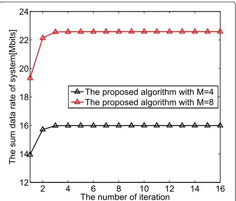
The convergence performance of the proposed Algo-rithm 1 and AlgoAlgo-rithm 2 is illustrated in Figs. 3 and4, respectively. Obviously, the sum data rate and energy effi-ciency can reach at local optimum within 15 steps. More-over, with the increase of the size of transmit antenna at the BS, sum data rate and energy efficiency are improved, but the convergence rates of the two proposed algorithms remain unchanged, which indicates the two proposed algorithms are insensitive to problem size.
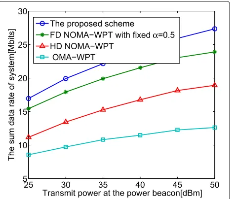
Figure 5 shows the sum data rate of system with the
change of the transmit power at the power beacon. As shown in this figure, the sum data rate of all schemes
Fig. 4Convergence of the proposed Algorithm2 under different number of transmit antennas at the BS
increases with the increase of transmit power at the power beacon. Moreover, the proposed scheme yields the best among all strategies. It is observed that NOMA systems deliver more sum data rate than OMA systems and FD mode brings more sum data rate performance gain.
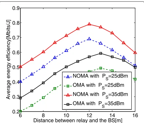
Figure6depicts the average energy efficiency versus the transmit power at power beacon. Different from sum data rate, performance gain would reach at a fixed value with the increase of transmit power at power beacon. Clearly, when transmit power at power beacon is 35 dBm, all schemes achieve an optimal balance between energy effi-ciency and energy consumption. In addition, performance
Fig. 5The sum data rate of system versus transmit power at the power beacon
Fig. 6The average energy efficiency versus transmit power at the power beacon
gain in NOMA systems is superior to OMA from the perspective of energy efficiency.
Figure7 presents the impact of self-interference level
on sum data rate of system forM = 4 andM = 2. As
shown, sum data rate of the FD scheme decreases with the increase of self-interference level, which demonstrates the necessity of self-interference cancellation. However, per-formance gain in FD scheme is still higher than that in HD one in terms of sum data rate.
Figure8 displays the location of the relay on average energy efficiency. Herein, assume that the BS is collinear with the far NOMA user U2 and the distance between the
−609 −50 −40 −30 −20 −10 0 10
11 12 13 14 15 16 17
Self−interference level [dB]
Sum data rate of system[Mbits]
The proposed scheme with M=4 The proposed scheme with M=2 HD NOMA−WPT with M=4 HD NOMA−WPT with M=2
6 8 10 12 14 16 0.2
0.3 0.4 0.5 0.6 0.7 0.8 0.9
Distance between relay and the BS[m]
Average energy efficiency[Mbits/J]
NOMA with PS=25dBm
OMA with PS=25dBm
NOMA with PS=35dBm
OMA with P
S=35dBm
Fig. 8Average energy efficiency versus distance between relay and the BS
BS and U2 is fixed, i.e., 24 m. It is observed that the aver-age energy efficiency first increases with the increase in the distance between relay and the BS and then decreases with the increase in the distance between relay and the BS. Apparently, when the relay is located in the middle of the BS and relay, energy efficiency performance can arrive at its maximum.
6 Conclusion
This paper studies spectral and energy efficiency of coop-erative NOMA system, where the BS and FD relay are powered by a power beacon. The transmit beamforming at the BS and relay and time allocation ratio are jointly optimized to maximize the sum data rate and energy efficiency. We propose iterative algorithms to solve the non-convex problems and analyzed the convergence of the proposed algorithms to make sure that the objectives of original problem converge to a KKT point. Simulation results have demonstrated the correctness and superiority of the proposed scheme.
7 Appendix
Sinceϕ (x,y)= xy2 is convex, thus it is true that
x2 y ≥2
¯ x∗x
¯ y −
|¯x|2 ¯
y2 y (38)
Following from [38], we have the below inequalities
ln
1+|x| 2
y
≥ln
1+|¯x|
2 ¯
y
−|¯x¯|2
y +
2R{¯x∗x}
¯
y −
|¯x|2|¯x|2+y ¯
y¯y+ |¯x|2
(39)
ln(1+ω)
v ≥
2 ln(1+ ¯ω)
¯
v +
¯
ω (ω¯+1)v¯−
¯
ω2
(ω¯+1)¯v
1
ω−
ln(1+ ¯ω)
¯
v2 v (40)
for allx∈ C,x¯ ∈C,y> 0, andy¯ >0, and over the trust region 2x∗x− |x∗|2>0.
Abbreviations
AF: Amplify-and-forward; AWGN: Additive white Gaussian noise; BS: Base station; CSI: Channel state information; DF: Decode-and-forward; EE: Energy efficiency; FD: Full-duplex; NOMA: Non-orthogonal multiple access; OMA: Orthogonal multiple access; QoS: Quality of service; SIC: Successive interference cancellation
Acknowledgements Not applicable.
Authors’ contributions
XL is the main author of the current paper. XL contributed to the development of the ideas, design of the study, theory, result analysis, and article writing. XL and JM conceived and designed the experiments. XL performed the experiments. JM undertook the revision works of the paper. Both authors read and approved the final manuscript.
Funding
This work was supported by the Educational Commission of Zhejiang Province (Y201840779) and Research Funded Project of Sichuan Provincial Department Education (18ZB0007).
Availability of data and materials
Data sharing is not applicable to this article as no datasets were generated or analyzed during the current study.
Competing interests
The authors declare that they have no competing interests.
Author details
1Department of Information Technology, Wenzhou Vocational and Technical
College, Wenzhou, 325000, China.2Department of Electronic Information and
Automation, ABA Teachers University, Wenchuan, 623002, China.
Received: 25 April 2019 Accepted: 11 July 2019
References
1. G. Wunder, et al., 5GNOW: non-orthogonal, asynchronous waveforms for future mobile applications. IEEE Commun. Mag.52(2), 97–105 (2014) 2. J. G. Andrews, et al., What will 5G be?. IEEE J. Sel. Areas Commun.32(6),
1065–1082 (2014)
3. A. Benjebbour, A. Li, Y. Saito, Y. Kishiyama, A. Harada, T. Nakamura, inProc. IEEE Globecom Workshops (GC Wkshps). System-level Performance of Downlink NOMA for Future LTE Enhancements (IEEE, Austin, 2013), pp. 66–70
4. K. Lee, T. Q. S. Quek, Hybrid full-/half-duplex system analysis in heterogeneous wireless networks. IEEE Trans. Wireless Commun.14(5), 2883–2895 (2015)
5. Z. Ding, et al., Cooperative non-orthogonal multiple access in 5G systems. IEEE Commun. Lett.19(8), 1462–1465 (2015)
6. J. B. Kim, I. H. Lee, Non-orthogonal multiple access in coordinated direct and relay transmission. IEEE Commun. Lett.19(11), 2037–2040 (2015) 7. Q. Liu, T. Lv, Z. Lin, Energy-efficient transmission design in cooperative
relaying systems using NOMA. IEEE Commun. Lett.22(3), 1–1 (2018) 8. G. Liu, F. R. Yu, H. Ji, V. C. M. Leung, X. Li, In-band full-duplex relaying: a
survey, research issues and challenges. IEEE Commun. Surveys Tuts.17(2), 500–524 (2015)
9. L. Chen, S. Han, W. Meng, C. Li, Optimal power allocation for dual-hop full-duplex decode-and-forward relay. IEEE Commun. Lett.19(3), 471–474 (2015)
11. G. Zheng, Joint beamforming optimization and power control for full-duplex MIMO two-way relay channel. IEEE Trans. Signal Process.63(3), 555–566 (2015)
12. C. Li, H. J. Yang, F. Sun, J. M. Cioffi, L. Yang, Adaptive overhearing in two-way multi-antenna relay channels. IEEE Sig. Process. Lett.23(1), 117–120 (2016)
13. Q. Wang, Y. Dong, X. Xu, X. Tao, Outage probability of full-duplex AF relaying with processing delay and residual self-interference. IEEE Commun. Lett.19(5), 783–786 (2015)
14. D. P. M. Osorio, E. E. B. Olivo, H. Alves, J. C. S. S. Filho, M. Latva-Aho, Exploiting the direct link in full-duplex amplify-and-forward relaying networks. IEEE Signal Process. Lett.22(10), 1766–1770 (2015) 15. C. Li, H. J. Yang, F. Sun, J. M. C. Yang, L. Yang, Ultiuser overhearing for
cooperative two-way multiantenna relays. IEEE Transactions Vehicular Technology.65(5), 3796–3802 (2016)
16. M. Heino, et al., Recent advances in antenna design and interference cancellation algorithms for in-band full duplex relays. IEEE Commun. Mag. 53(5), 91–101 (2015)
17. A. Sabharwal, P. Schniter, D. Guo, D. W. Bliss, S. Rangarajan, R. Wichman, In-band full-duplex wireless: challenges and opportunities. IEEE J. Sel. Areas Commun.32(9), 1637–1652 (2014)
18. W. Wu, F. Zhou, P. Li, P. Deng, B. Wang, V. C. M. Leung, in2019 IEEE International Conference on Communications (ICC), Shanghai, China. Energy-Efficient Secure NOMA-Enabled Mobile Edge Computing Networks (IEEE, Shanghai, 2019)
19. M. Duarte, C. Dick, A. Sabharwal, Experiment-driven characterization of full-duplex wireless systems. IEEE Trans. Wireless Commun.11(12), 4296–4307 (2012)
20. C. Zhong, Z. Zhang, Non-orthogonal multiple access with cooperative full-duplex relaying. IEEE Commun. Lett.20(12), 2478–2481 (2016) 21. Z. Zhang, Z. Ma, M. Xiao, Z. Ding, P. Fan, Full-duplex device-to-device
aided cooperative non-orthogonal multiple access. IEEE Trans. Veh. Technol.66(5), 4467–4471 (2017)
22. L. Zhang, J. Liu, M. Xiao, G. Wu, Y. C. Liang, S. Li, Performance analysis and optimization in downlink NOMA systems with cooperative full-duplex relaying. IEEE J. Sel. Areas Commun.35(10), 2398–2412 (2017) 23. E. Hossain, M. Rasti, H. Tabassum, A. Abdelnasser, Evolution toward 5G
multi-tier cellular wireless networks: an interference management perspective. IEEE Wireless Commun.21(3), 118–127 (2014)
24. V. Raghunathan, S. Ganeriwal, M. Srivastava, Emerging techniques for long lived wireless sensor networks. IEEE Commun. Mag.44(4), 108–114 (2006) 25. K. Pentikousis, In search of energy-efficient mobile networking. IEEE
Commun. Mag.48(1), 95–103 (2010)
26. T. Chen, Y. Yang, H. Zhang, H. Kim, K. Horneman, Network energy saving technologies for green wireless access networks. IEEE Wireless Commun. 18(5), 30–38 (2011)
27. Z. Zhu, Z. Chu, Z. Wang, I. Lee, Outage constrained robust beamforming for secure broadcasting systems with energy harvesting. IEEE Transactions on Wireless Communications.15(11), 7610–7620 (2016)
28. Y. Liu, Z. Ding, M. Elkashlan, H. V. Poor, Cooperative non-orthogonal multiple access with simultaneous wireless information and power transfer. IEEE J. Sel. Areas Commun.34(4), 938–953 (2016)
29. Y. Xu, et al., Joint beamforming and power-splitting control in downlink cooperative SWIPT NOMA systems. IEEE Trans. Signal Process.65(18), 4874–4886 (2017)
30. Y. Alasaba, C. Y. Leow, S. K. A. Rahim, Full-duplex cooperative non-orthogonal multiple access with beamforming and energy harvesting. IEEE Access.6, 19726–19738 (2018)
31. C. Li, S. Zhang, P. Liu, F. Sun, J. M. Cioffi, L. Yang, Overhearing protocol design exploiting inter-cell interference in cooperative green networks. IEEE Transactions Vehicular Technology.65(1), 441–446 (2016)
32. Z. Zhu, Z. Chu, N. Wang, S. Huang, Z. Wang, I. Lee, Beamforming and power splitting designs for AN-aided secure multi-user MIMO SWIPT systems. IEEE Trans. Information Forensics and Security.12(12), 2861–2874 (2017) 33. C. Li, F. Sun, J. M. Cioffi, L. Yang, Energy efficient MIMO relay transmissions
via joint power allocations. IEEE Transactions on Circuits and Systems. 61(7), 531–535 (2014)
34. W. Wu, B. Wang, Robust secrecy beamforming for wireless information and power transfer in multiuser MISO communication system. EURASIP Journal on Wireless Communications and Networking. 2015.1(2015):161
35. C. Li, P. Liu, C. Zou, F. Sun, J. M. Cioffi, L. Yang, Spectral-efficient cellular communications with coexistent one- and two-hop transmissions. IEEE Transactions on Vehicular Technology.65(8), 6765–6772 (2016) 36. H. Tuy,Convex Analysis and Global Optimization. (Kluwer Academic, Hanoi,
2001)
37. H. H. M. Tam, et al., Successive convex quadratic programming for quality-of-service management in full-duplex MU-MIMO multicell networks. IEEE Trans. Commun.64(6), 2340–2353 (2016)
38. V. D. Nguyen, H. D. Tuan, T. Q. Duong, O. S. Shin, H. V. Poor, Joint fractional time allocation and beamforming for downlink multiuser MISO systems. IEEE Communication Letters.21(12), 2650–2653 (2017)
Publisher’s Note