Circularly Polarized Dodecagonal Patch Antenna with Polygonal
Slot for RFID Applications
Karavilavadakkethil C. Prakash*, Sumitha Mathew, Ramachandran Anitha, Puthiyapurayil V. Vinesh, Methapettyparambu P. Jayakrishnan,
Pezholil Mohanan, and Kesavath Vasudevan
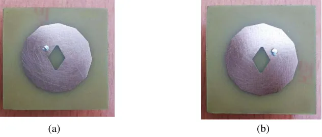
Abstract—This paper presents a compact 2.45 GHz single feed directional circularly polarized (CP) microstrip antenna for radio frequency identification (RFID) applications. The proposed antenna comprises a dodecagonal microstrip patch embedded with an irregular polygonal slot, fabricated on an FR4 substrate. Two antennas, one with right-handed circular polarization (RHCP) and the other with left-handed circular polarization (LHCP), both resonating at a frequency of 2.45 GHz are presented. The measurement results show a 3 dB axial ratio bandwidth of 5.5%, a 10 dB impedance bandwidth of 5.7% for both the antennas, a peak gain of 4.82 dBi for RHCP antenna and 4.67 dBi for LHCP antenna. In addition, the antennas provide symmetrical patterns with 88◦ half-power beam width. The overall size of the antenna is 50 mm×50 mm×1.6 mm and offers an area reduction of 21.17%.
1. INTRODUCTION
Usage of circularly polarized (CP) antenna in wireless systems is an effective way to mitigate multi-path effects. Hence CP antenna is widely accepted as a key subsystem for various wireless systems including RFID [1]. It is possible to avoid the false identification of targeted objects by RFID readers if the antennas used are circularly polarized. A single co-axial fed circularly polarized antenna is simpler in its structure than dual-fed ones, as it can excite CP radiation without using an external polarizer. In a singly fed CP antenna, the generated mode is usually excited in an electrically thin cavity region of the microstrip antenna. The generated mode is separated into two orthogonal modes by the effect of a perturbation segment such as a slot, truncated segment or other asymmetries. A wide variety of perturbation methods have been adopted in literature for designing a single feed circularly polarized microstrip antenna. One ‘V’ shaped slot embedded into a cross shaped rectangular patch antenna [2], square patch embedded with a cross slot and an L-shaped open-end microstrip line linked to a tag chip, terminated by a shorting pin on the other end and capacitively coupled to the patch [3], an arrowhead-shaped slot is embedded in the first quadrant along the diagonal axes of a square patch [4], a circular patch antenna with central elliptical slot [5], two stacked patches fed with an S-shaped impedance-matching network [6] are some of the distinct techniques employed to excite circularly polarized radiation.
In this work, a novel microstrip patch antenna — 12 sided polygon (dodecagon) shaped patch — with the perturbation technique of embedding a central irregular hexagon shaped slot, for exciting CP radiation designed for the 2.45 GHz band is proposed. Good CP bandwidth and compactness is achieved on account of the central slot. The structure exhibits good impedance matching, gain and circularly polarized radiation characteristics over the entire operating band.
Received 3 November 2015, Accepted 16 December 2015, Scheduled 23 December 2015 * Corresponding author: Karavilavadakkethil Chellappan Prakash ([email protected]).
2. ANTENNA GEOMETRY
The proposed antenna is designed on an FR4 substrate of size 50 mm×50 mm×1.6 mm, with dielectric constant 4.4, thickness 1.6 mm and tanδ= 0.02.
By introducing some asymmetry in the structure, the resonant frequencies of two degenerate modes can be made slightly different from each other with equal amplitude and a phase difference of 90◦ between them, for producing CP. The simplest way to split the fundamental mode is, to cut a slit through the center [5]. The novelty in this work is the selection of shape for the patch and the method of introducing asymmetry by means of the irregular hexagonal slot as depicted in Figure 1(d). The slot is positioned in the center of the patch and oriented along the X axis. The dimensions of the slot are chosen such thatb < c < d. The parameter ‘k’ is defined as the ratio, ‘d’ to ‘c’ with ‘b’ constant. The choice of dimensions of the slot and the feed position ensure the splitting of the fundamental mode into degenerate modes and phase quadrature between them. The radiation of circularly polarized wave is highly sensitive with respect to the position of the feed point and the dimensions of the central slot [5]. The antenna is excited through the co-axial probe at the location ‘X’ to produce Right Handed Circular Polarization (RHCP) and at the feed location ‘Y’ to radiate electromagnetic waves with Left Handed Circular Polarization (LHCP). The feed point for RHCP antenna is the mirror image as that of the LHCP antenna with respect to the center of the patch, chosen along the locus of 50 Ω characteristic impedance and is adjusted for the best matching.
(a) (b) (c) (d)
Figure 1. Geometry of the proposed antenna. (a) Side view, (b) top view of the RHCP antenna, (c) top view of the LHCP antenna and (d) the central slot geometry. Guided wavelength λg = 0.0604 m,
a= 8.28 mm (0.137λg), b= 1 mm (0.0166λg), c= 8 mm (0.1325λg), d= 11.4 mm (0.189λg), k= 1.425,
L=W = 50 mm (0.8278λg),X (29 mm, 19.8 mm) andY (29 mm, 30.2 mm).
3. DESIGN
In order to design the dodecagonal patch antenna, the design of the circular patch antenna is considered first, as it is closely related to the proposed structure [7]. The side length ‘a’ of the regular dodecagon for a resonant frequency offr= 2.77 GHz is computed as follows. The dominant mode resonance frequency of a circular patch is given by [7] as,
fr= Xmnc
2πre√r (1)
where ‘fr’ is the resonant frequency of the patch,Xmn = 1.8412 for the dominant mode TM11, ‘re’ the
effective radius of the equivalent circular patch,
re=r
1− 2h
πrεr
lnπr
2h + 1.7726
0.5
where ‘r’ is the radius of the circular patch and ‘h’ the height of the substrate. The edge of the regular dodecagon ‘a’ may be found out [7] as,
a=re√ π
11.196 (3)
When a patch antenna is considered, its mode impedanceZmn(ω) may be expressed [5] as,
Zmn(ω) =Rmnζmn(ω) (4) where ‘mn’ represents the mode,m, n= 0 to∞;Rmnrepresents the sum of the radiation, dielectric and metal losses; ζmn(ω) is the normalized frequency response written in terms of the quality factor Qmn
and modal resonance frequency ωmn. The quality factor Q depends to a large extent on the antenna geometry. By the proper selection of the feed point, the dominant mode is detuned into two equal amplitude orthogonal degenerate modes, orthogonal even mode TMe and orthogonal odd mode TMo, without considering the higher order modes. Even mode is the mode that is symmetric with respect to the Y axis and odd mode is symmetric with respect to the X axis. Correspondingly total input impedance may be written [5] as,
Zin=Ze+Zo (5)
whereZeandZoare the even mode and odd mode impedances respectively. ωeis the even mode angular frequency and ωo the odd mode angular frequency, with ωe < ωo. By introducing the asymmetry, the resonant frequencies of two degenerate modes are made slightly different from each other. The normalized impedance ratio is defined [5] as,
βζ(ω) = ζo(ω)
ζe(ω) =
1 +jQ
ω ωe −
ωe ω
1 +jQ
ω ωo −
ωo ω
(6)
where ‘Q’ is the quality factor and assumed to be the same for the detuned modes. The angle ofβζ(ω) is the phase difference of the CP field components, while the magnitude is proportional to the axial ratio. Here the angle ofβζ(ω) is designed to be 90◦ and the magnitude to be less than 3 dB. The fundamental mode splits into degenerate orthogonal modes, where for the odd mode, which is oriented towards the slot (X axis), the perturbation is minimum, being the top and bottom width of the slot is narrow enough. If the slot had been a rectangular geometry with width ‘b’ and height ‘d’, with no change in orientation, the odd mode surface current would not have been affected by this perturbation and the resonant angular frequency would have been approximately same as that of the fundamental resonant frequency [8]. In the even mode (oriented about the Y axis), the surface current is forced to traverse more length around the slot and hence the resonant frequency ωe is reduced. If a second orthogonal cut is made at the center [3], it will enhance the electrical path of the odd mode and the corresponding resonant frequency will be reduced. In the proposed structure, instead of making an orthogonal cut, the central width of the hexagonal slot is made larger than the top and bottom width. The effect of the
(a) (b)
second orthogonal cut is achieved due to this enhancement of central width. As in the case of even mode, current in the odd mode also has to traverse more length and therefore resonant frequency is reduced. By selecting appropriate dimensions for the slot, the two degenerate mode frequencies are made nearly equal. The central slot, thus introduces annular effect and thereby enhanced bandwidth [8]. Though the edge of the dodecagonal patch is designed for a resonant frequency of 2.77 GHz, due to the presence of the central slot the resonant frequency is reduced to 2.45 GHz and hence an area reduction of 21.17% is achieved.
4. RESULTS AND DISCUSSION
Using the computed parameters, the structure is simulated using Ansys HFSS13.0. The simulation graphs of return loss, axial ratio and surface current pattern are plotted and depicted in Figures 3 to 5. Antenna prototypes are fabricated on an FR4 substrate with optimized parameters and the antenna measurements are done using the ZVB20 Network Analyzer. The measured and simulated reflection characteristics of the RHCP antenna are compared in Figure 3. It is noted that the fundamental resonant frequency of the antenna without slot is 2.77 GHz, whereas with slot the simulated resonant frequency is 2.46 GHz and the experimental result is 2.45 GHz. A variation of the axial ratio with ‘k’ is studied by simulation as in Figure 4. It is observed that when the value ofk≥1.25, axial ratio becomes less than 3 dB and thus one criterion for CP radiation is satisfied. k= 1.425 gives good results.
Figure 3. S11plots of the proposed antennas. Figure 4. Axial ratio plot.
ϕ = 0o ϕ = 90o ϕ = 180o ϕ = 270o
(a) (b) (c) (d)
The surface current distributions simulated for RHCP antenna at the center frequency of 2.45 GHz are plotted in Figure 5. Surface current distribution at the excitation phase angle ϕ= 0◦ is equal in magnitude and opposite in direction to that atϕ= 180◦. Same is the case of surface current distribution at ϕ= 90◦ and ϕ= 270◦. It is true for both the antennas and hence the criterion for CP is satisfied. As the direction of view chosen as +Z-axis, the direction of rotation of current is anticlockwise and the sense of polarization is confirmed as left handed circular polarization for the feed positionY. The direction of rotation of current is clockwise and the sense of polarization is confirmed as right handed circular polarization for the feed positionX. The sense of polarization is also tested and verified using
Figure 6. Plots of received power by RHCP and LHCP helical antennas.
Figure 7. Simulated Smith chart of the RHCP and LHCP antennas.
(a) (b)
helical antennas designed at the measured resonant frequency 2.45 GHz as per the design methodology in [9, 10] and Figure 6 depicts corresponding received power plots. The simulated Smith chart depicted in Figure 7 indicates a dip marked at the center frequency 2.45 GHz corresponding to RHCP and LHCP antennas. Hence the excitation of two orthogonal degenerate modes in both the antennas is confirmed, justifying the circularly polarized radiation [11].
The measured radiation patterns of RHCP and LHCP antennas in the XZ and Y Z planes for
ϕ= 0◦ and 90◦ are plotted in Figure 8. The patterns are almost identical. The gain is measured using gain-comparison method and depicted in Figure 9. It is observed that the gain is slightly more for the RHCP antenna than that of the LHCP antenna.
The measured values of the proposed RHCP and LHCP antennas are compared to the circular
Figure 9. Measured gain plot of the proposed antennas.
Table 1. Comparison of measured values of the proposed antennas with the circular patch.
Parameter
Circular patch antenna with elliptical slot [5]
Proposed RHCP antenna
Proposed LHCP antenna
Center frequency 2.45 GHz 2.45 GHz 2.45 GHz
Return loss 19 dB 24.8 dB 22 dB
Gain 3.85 dBi 4.82 dBi 4.67 dBi
Minimum axial ratio 0 dB 0.06 dB 0.2 dB
Axial ratio bandwidth 30 MHz (1.22%) 135 MHz (5.5%) 135 MHz (5.5%)
10 dB impedance bandwidth 130 MHz (5.3%) 140 MHz (5.7%) 140 Hz (5.7%)
3 dB Beam width - 88◦ 88◦
Area reduction 9.5% 21.17% 21.17%
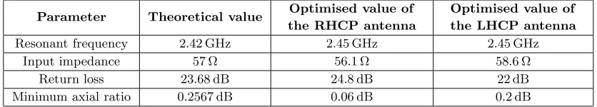
Table 2. Comparison of theoretical and optimized values of the proposed antennas.
Parameter Theoretical value Optimised value of the RHCP antenna
Optimised value of the LHCP antenna
Resonant frequency 2.42 GHz 2.45 GHz 2.45 GHz
Input impedance 57 Ω 56.1 Ω 58.6 Ω
Return loss 23.68 dB 24.8 dB 22 dB
patch antenna [5] and tabulated in Table 1. Theoretical values of the following antenna parameters for the proposed antennas are computed [10, 12], compared with the optimized values and tabulated in Table 2.
Here the theoretical value of the resonant frequency is computed based on 14.81% increase in electrical length due to the central slot on the patch antennas.
5. CONCLUSION
A single feed circularly polarized irregular hexagonal slotted regular dodecagonal patch antenna has been designed, simulated and experimentally investigated. The structure is novel due to the choice of dodecagon shape for the patch and the central hexagonal slot perturbation method. The antennas cover RFID band with a center frequency of 2.45 GHz, with broadside radiation characteristics. The measured 10 dB impedance and 3 dB axial ratio bandwidths confirm the usefulness of the structures to industrial, scientific and medical (ISM) bands in handheld RFID reader applications.
ACKNOWLEDGMENT
The authors acknowledge the University Grants Commission (UGC), for financial assistance by providing the teacher fellowship under the Faculty Development Programme; Sree Ayyappa College, Travancore Devaswom Board Management and the University of Kerala for providing the opportunity.
REFERENCES
1. James, J. R. and P. S. Hall,Handbook of Microstrip Antennas, Peter Peregrinus Ltd., London, UK, 1989.
2. Nishamol, M. S., V. P. Sarin, D. Tony, C. K. Aanandan, P. Mohanan, and K. Vasudevan, “Design of a circularly polarized rectangular microstrip antenna for GPS applications,” Microwave and Optical Technology Letters, Vol. 53, No. 2, 468–470, 2011.
3. Chen, H.-D., S.-H. Kuo, C.-Y.-D. Sim, and C.-H. Tsai, “Coupling-feed circularly polarized RFID tag antenna mountable on metallic surface,” IEEE Transactions on Antennas and Propagation, Vol. 60, No. 5, May 2012.
4. Gautam, A. K., A. Kunwar, and B. K. Kanaujia, “Circularly polarized arrowhead-shape slotted microstrip antenna,”IEEE Antennas Wireless Propagation Letters, Vol. 13, 471–474, 2014. 5. Stefano, M. and A. C. G. Manes, “A new design method for single-feed circular polarization
microstrip antenna with an arbitrary impedance matching condition,” IEEE Transactions on Antennas and Propagation, Vol. 59, No. 2, 379–389, 2011.
6. Wu, T., H. Su, L. Gan, H. Chen, J. Huang, and H. Zhang, “A compact and broadband microstrip stacked patch antenna with circular polarization for 2.45-GHz mobile RFID reader,” IEEE Antennas Wireless Propagation Letters, Vol. 12, 623–626, 2013.
7. Nagendra, K. and R. Kumar, “Design of slotted ground hexagonal microstrip patch antenna and gain improvement with FSS screen,” Progress In Electromagnetics Research B, Vol. 51, 177–199, 2013.
8. Bhattacharyya, A. and L. Shafai, “A wider band microstrip antenna for circular polarization,” IEEE Transactions on Antennas and Propagation, Vol. 36, No. 2, 157–163, 1988.
9. Garg, R., P. Bhartia, I. Bahl, and A. Ittipiboon, Microstrip Antenna Design Handbook, Artech House, London, 2001.
10. Balanis, C. A., Antenna Theory: Analysis and Design, 2nd Edition, John Wiley & Sons, Inc., New Delhi, 2007.
11. Gao, S.(Shichang), Q. Luo, and F. Zhu, Circularly Polarized Antennas, John Wiley & Sons Ltd, United Kingdom, 2014.