USING GENETIC ALGORITHM TO REDUCE THE RADAR CROSS SECTION OF THREE-DIMENSIONAL ANISOTROPIC IMPEDANCE OBJECT
H.-T. Chen, G.-Q. Zhu, and S.-Y. He†
School of Electronic Information Wuhan University
Wuhan 430079, China
Abstract—This paper focuses on the radar cross section (RCS) reduction for the three-dimensional object with anisotropic impedance coating. In this work, a genetic algorithm is adopted to optimize the RCS of the anisotropic impedance object in desired angle range. The surface impedances are considered as the optimized parameters and the scattering of the object is computed by the PO method. The optimization process is demonstrated by considering the RCS reduction of two typical targets: the cone and the cone/cylinder composite structure. It is found that the optimization process can reduce the RCS of the targets remarkably and the anisotropic impedance coating has better RCS reduced effect than the isotropic impedance coating.
1. INTRODUCTION
Radar cross section (RCS) reduction of various objects is the key technique in radar counterwork and is of great importance in military fields [1–13]. Two major means for radar cross section (RCS) reduction is shaping and radar absorbing material (RAM) coating. The RAM absorbs the incident radar wave and reduces the return wave. Coating the object with anisotropic RAM can not only absorb the incident radar wave, but also redistribute the scattering energy in the whole space by adjusting the principal axis of the anisotropic material. For most anisotropic coated objects, the surface boundary can be approximated by anisotropic impedance boundary condition (IBC). The electromagnetic problems involving with anisotropic IBC have † The first author is also with Wuhan Maritime Communication Research Institute, Wuhan
been of interest for a long time. The diffraction of the impedance wedge was studied firstly by Maliuzhinets [14]. Based on Maliuzhinets’ method, the UTD technique for anisotropic impedance wedge was established and improved by Manara et al. [15], Pelosi et al. [16], and Yuan et al. [17] successively. A MM/PO hybrid method was presented to model the currents of an infinite wedge with tensor impedance boundary conditions by Bilow [18] and the improvement to this problem was made by Gong et al. [19]. For the three-dimensional problems, a physical optics technique for anisotropic impedance flat plates was presented by Pelosi et al. [20]. However, the corresponding inverse problem, the optimization of the scattering characteristics for the anisotropic impedance target, was rarely investigated in the published literatures.
The purpose of this paper is to reduce the RCS of the targets with anisotropic impedance surface by using genetic algorithm (GA) for optimization. The GA has been used widely in electromagnetic optimization problem [21–25]. A RCS reduction process for RAM based on GA has been proposed by Mosallaei et al. [26], where the material parameters and thickness were optimized for the canonical targets coated with multilayered lossy material. In this presented work, the surface impedances and the direction of the principal anisotropic axis are considered as the optimized parameters, while the PO technique proposed by Pelosi et al. [20] is adopted as the forward-arithmetic to model the RCS of the targets. As a comparison, the optimization of RCS for the isotropic impedance object is also presented in this paper. It is observed that the anisotropic impedance coating has better RCS reduction than the isotropic impedance coating.
In the following section, the GA optimization process and the PO technique for the anisotropic impedance targets is summarized. In Section 3, the optimization process will be demonstrated by considering two typical examples. The conclusion of this paper and the proposition for further investigation are stated in Section 4.
2. RCS REDUCTION FOR IMPEDANCE TARGETS BASED ON GA AND PO
Figure 1. Anisotropic impedance object illuminated by an EM plane wave.
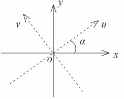
Figure 2. The local referenced coordinates x, y on the surface of the target and the principal directions u, v of the anisotropic surface impedance. x,y are selected as the tangent vectors of the surface.
the axis x with an angle α which is named as the principal angle in the following.
In Pelosi’s work [20], only the special case that the principal directions parallel to the referenced coordinates was considered. For an arbitrary three-dimensional target, this limitation always can not be satisfied. The PO expressions for the general case in which the principal directions are deflected from the referenced coordinates should be investigated.
Within the local reference framexoy, the surface impedance can be defined as,
Ex Ey
=
Zxx Zxy Zyx Zyy
−Hy Hx
coordinatesuov as, Eu Ev =
Zuu 0
0 Zvv
−Hv Hu
(2) The coordinates transform relationshipcan be written as follows,
Eu Ev =
cosα sinα −sinα cosα
Ex Ey
(3)
−Hv Hu
=
cosα sinα −sinα cosα
−Hy Hx
(4) Then, the surface impedance within the reference frame xoy can be formulated as
Zxx Zxy Zyx Zyy
=
cos2αZ
uu+ sin2αZvv cosαsinα(Zuu−Zvv)
cosαsinα(Zuu−Zvv) cos2αZvv+ sin2αZuu
(5) With the same techniques presented in [20], the PO currents in the illuminating region of the target’s surface can be formulated as follows
JP Os = 1
Z0
(1−R22)E⊥i −R21Ei//
cosθ0ˆe⊥
+ 1
Z0
R12E⊥i + (1 +R11)E//i
(ˆn×eˆ⊥) (6)
JP Oms =
(1−R11)E//i −R12E⊥i
cosθ0eˆ⊥ −R21E//i + (1 +R22)E⊥i
(ˆn×eˆ⊥) (7)
whereZ0is the free-space intrinsic impedance. R= [R11, R12;R21, R22]
is the tensor reflect coefficient of the anisotropic surface. The meaning of the parameters and the detailed formulation for the reflect coefficient are described in the Appendix.
each patch can be expressed as
Es = jk0e−
jk0r
4πr e jk0ˆk·rc
η0rˆ×rˆ×
Jes0+ ˆr×
Jms0
e−jk0rc·
(ˆk−ˆr)−
w · 3 n=1
w∗·rn+1−
rn
w 2
sin k0 w·
rn+1−
rn 2 k0 w·
rn+1−
rn
2
e−jk0
r n+1+r n
2 (8)
where rc is the center of the triangle patch and
Jes0,
Jms0 are the
currents at the center. In (8), ˆr defines the direction of observation,
rn and
rn+1 are the start point and the end point of the nth edge of
the triangle patch, wand w∗ are the vectors defined in [20, 27]. In radar engineering, the RCS of targets in some special angle region, for example, the nose direction of the fighter plane is of the most interest and expected to be reduced for avoiding the enemy radar. The requirement of the RCS reduction for the anisotropic impedance target can be expressed to search the maximum of the following object function,
F(Zuu, Zvv, α) =
1
N
n=1
[σ(θn, ϕn)]2
(9)
whereN is the number of samples in the concerned angle region. σ is the monostatic RCS and Zuu, Zvv, α are the surface impedance and
the principal angle.
The GA optimization process is applied in this work to search the maximum of (9). Since the optimized parameters in the GA should be real number, the optimized parameters can be set as: Real(Zuu),
Imag(Zuu), Real(Zvv), Imag(Zvv), α. If the target is divided into M
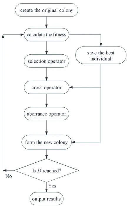
Figure 3. Flow chart of the genetic algorithm.
output it as the optimized solution. In this study, the size of the colony L is chosen as 100, and the number of the evolutional time D
is also chosen as 100.
3. EXAMPLES OF RCS REDUCTION FOR TYPICAL TARGETS
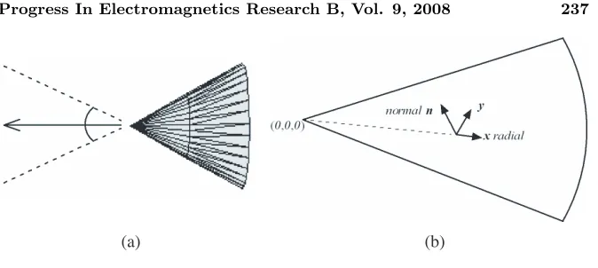
(a) (b)
Figure 4. (a) The anisotropic impedance cone and (b) the corresponding local reference frame.
Figure 5. The convergence of the GA process.
impedance coating and the isotropic impedance coating is shown. 3.1. RCS Reduction for a Cone
The head of many aircrafts, which has the most important effect on the back-scattering in nose direction, can be approximated by a cone. So the RCS reduction procedure starts from this typical target. As shown in Fig. 4, an impedance cone is illuminated by a plane wave with parallel polarization. The height of the cone is 10λ0, and the radius of
Table 1. The optimized results of the anisotropic surface impedance for the cone.
optimized parameters values
Zuu (0.48−0.0342j)Z0 Zvv (2.53 + 0.23j)Z0
α α= 182◦
the cone are shown in Fig. 4(b). The RCS within±30◦around the nose direction is expected to be reduced by the optimization, considering the impedance surface as the optimized parameters.
The convergent process of the GA optimization process for this example is shown in Fig. 5. It can be seen that the GA process reaches its optimized value after about 50 iterative steps. The optimized results of the surface impedance are listed in Table 1. The real part of the surface impedance is the surface resistance which represents the loss of the surface, and the image part is the surface reactance while the positive sign means the inductive surface and the negative sign means the capacitive surface.
In order to compare the RCS reduction effect between the anisotropic coating and the isotropic coating, the optimization for an isotropic impedance cone is also completed, where the surface impedance is the only optimized parameter and the optimized result givesZs= (0.767−0.083j)Z0.
Figure 7. RCS of the anisotropic impedance cones with different principal axis direction.
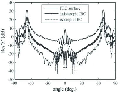
The RCS of the cone with PEC surface, with optimized anisotropic impedance surface, and that with optimized isotropic impedance surface are shown in Fig. 6 simultaneously where 0◦ refered to the nose direction. It can be seen from Fig. 6 that both the optimized anisotropic coating and isotropic coating reduce the RCS evidently within the angle range ±30◦. Compared to the isotropic coating, the anisotropic coating has better RCS reduction effect within ±20◦, especially at the nose direction where the anisotropic coating has more than 10 dB advantage than the isotropic coating. However, during the angle region 20◦–30◦ departing from the nose direction, the RCS of the anisotropic coating is a little higher than the isotropic coating. It can be explained that the anisotropic coating distributes the scattering energy of the peak at 0◦ to a wide-angle region. Since the RCS of the anisotropic coating and isotropic coating are both very low (<15 dB) in 20◦–30◦ and −30◦–20◦, the RCS reduction effect of the anisotropic coating is better than the isotropic impedance coating in the angle region that we care about.
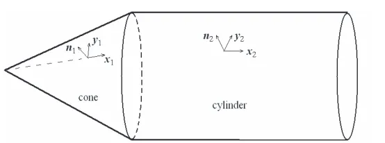
Figure 8. Composite structure of a cone and a cylinder. The local reference frames are marked as (x1, y1, n1) and (x2, y2, n2)
respectively.
3.2. RCS Reduction for the Composite Structure of a Cone and a Cylinder
The composite structure of a cone and a cylinder, as shown in Fig. 8, is considered. This structure can be used to approximate the shape of the ballistic missile. The height of the cone is 10λ0, the length of the
cylinder is 30λ0, and the radius of the bottom is 4λ0. The ballistic
missile will welter when it is flying, so it is necessary to consider the RCS reduction for the radar wave with arbitrary polarization. For an arbitrary polarization, it can be decomposed into the parallel polarization part and the vertical polarization part. If a target has low RCS for both parallel polarization and vertical polarization, it will have low RCS for the radar wave with arbitrary polarization. Therefore, we can assume the polarization angle of the incident wave is 45◦ when the parallel polarization part and the vertical polarization part are equal. Then the object function (9) is modified as following
F(Zuu, Zvv, α) =
1
N
n=1
σ//2 +σ⊥2
(10)
where σ// and σ⊥ are the RCS contributed from parallel part and
vertical part of the scattering fields respectively.
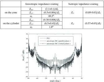
The optimized results for the anisotropic impedance coating and the isotropic coating are listed in Table 2 simultaneously. The RCS reduction effect of the two kind of coating is shown in Fig. 9 and Fig. 10 respectively. And the comparison of RCS reduction within
±30◦ around the nose direction is given in Fig. 11.
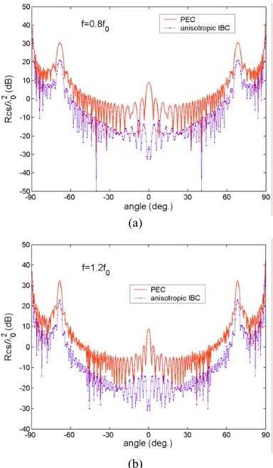
Table 2. The optimized results of the anisotropic surface impedance and isotropic surface impedance for the composite structure of cone and cylinder.
Anisotropic impedance coating Isotropic impedance coating
Zuu1 (2.1+0.1j)Z0
Zvv1 (0.5+0.004j)Z0
on the cone
α1 89.3
Zs1 (0.89-0.03j)Z0
Zuu2 (0.38-0.006j)Z0
Zvv2 (6.5+0.45j)Z0
on the cylinder
α2 1.8
Zs2 (0.57+0.03j)Z0
Figure 9. RCS reduction effect of the anisotropic impedance coating to the composite structure of cone and cylinder for radar wave with parallel polarization and vertical polarization respectively.
the vertical polarization. The results show that the anisotropic impedance coating has the better RCS reduction effect than the isotropic impedance coating for radar wave with arbitrary polarization, especially when it is near to the nose direction.
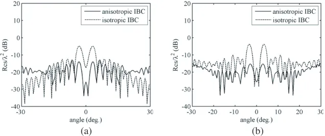
Although the RCS optimization process describes above is implemented at a single frequency, it also can obtain good RCS reduction effect in a relative broad frequency range. The RCS reduction effect of the anisotropic impedance coating listed in Table 2 for different frequency is demonstrated in Fig. 12. The radar wave is assumed as parallel polarization. In Fig. 12a, the frequency is 0.8f0
Figure 10. RCS reduction effect of the isotropic impedance coating to the composite structure of cone and cylinder for radar wave with parallel polarization and vertical polarization respectively.
(a) (b)
Figure 11. Comparing of the RCS reduction between anisotropic coating and isotropic coating for the composite structure of cone and cylinder. Incident radar wave: (a) parallel polarization; (b) vertical polarization.
(a)
(b)
Figure 12. RCS reduction effect of the anisotropic coating listed in Table 2 for different frequency.
4. CONCLUSION
ACKNOWLEDGMENT
This work is supported by the National Natural Science Foundation of China under Grant 60671040.
APPENDIX A.
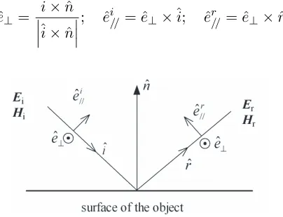
In this appendix, the PO currents of an anisotropic impedance plate illuminated by plane wave are presented. Firstly, a radial coordinate as shown in Fig. A1 is established and the accessorial vectors are defined as,
ˆ
e⊥= ˆi×nˆ ˆi×nˆ ; eˆ
i
//= ˆe⊥׈i; eˆ r
//= ˆe⊥×rˆ (A1)
Figure A1. The radial coordinate and the accessorial vectors. The incident and reflect fields can be decomposed into parallel polarization part and vertical polarization part which can be written as
Ei = E//i ˆe//i +E⊥ieˆ⊥;
Hi =H//i eˆ//i +H⊥ieˆ⊥ (A2)
Er = E//rˆe//r +E⊥reˆ⊥;
Hr=H//rˆe//r +H⊥rˆe⊥ (A3)
Using the reflect coefficients of the plate, the relation between reflect fields and incident fields can be written as,
E//r Er
⊥
=
R11 R12 R21 R22
E//i E⊥i
;
H⊥r H//r
=
R11 −R12 −R21 R22
H⊥i Hi
//
(A4)
(a) (b)
Figure A2. Geometry of the local reference coordinates and the incident direction. (a) Three-dimension; (b) on the xoy plane.
Fig. A2(b), the coordinates transform relationshipcan be written as following,
E⊥ Eτ
=
cosχ sinχ −sinχ cosχ
Ey Ex
;
H⊥ Hτ
=
cosχ sinχ −sinχ cosχ
Hy Hx
(A5) Utilizing Equations (A2–A5) and the anisotropic IBC Equa-tion (1), it can be obtained the expressions of the reflect coefficients as following,
R11 =
Dcos2θ
0−ADcosθ0+BCcosθ0−cosθ0+A Dcos2θ
0+ADcosθ0−BCcosθ0−cosθ0−A
(A6a)
R12 = −
2Bcosθ0 Dcos2θ
0+ADcosθ0−BCcosθ0−cosθ0−A
(A6b)
R12 = −
2Ccosθ0 Dcos2θ
0+ADcosθ0−BCcosθ0−cosθ0−A
(A6c)
R11 =
Dcos2θ0+ADcosθ0−BCcosθ0+ cosθ0+A Dcos2θ
0+ADcosθ0−BCcosθ0−cosθ0−A
where
A= 1
Z0
Zxxsin2χ+Zyycos2χ−Zxysinχcosχ−Zyxsinχcosχ
(A7a)
B= 1
Z0
Zxysin2χ−Zyxcos2χ+Zxxsinχcosχ−Zyysinχcosχ
(A7b)
C= 1
Z0
Zxysin2χ−Zyxcos2χ+Zxxsinχcosχ−Zyysinχcosχ
(A7c)
D=− 1
Z0
Zyysin2χ+Zxxcos2χ+Zxysinχcosχ+Zyxsinχcosχ
(A7d) When the principal directions are parallel to the reference coordinates, Zxy and Zyx are vanished and the expressions of reflect
coefficients will be degenerated to the same form as in [8]. REFERENCES
1. Lee, K.-C., C.-W. Huang, and M.-C. Fang, “Radar target recognition by projected features of frequency-diversity RCS,”
Progress In Electromagnetics Research, PIER 81, 121–133, 2008.
2. Hu, C.-F., J.-D. Xu, N. Li, and L. Zhang, “Indoor accurate RCS measurement technique on UHF band,” Progress In
Electromagnetics Research, PIER 81, 279–289, 2008.
3. Tao, Y. B., H. Lin, and H. J. Bao, “Kd-tree based fast ray tracing for RCS,” Prediction Progress In Electromagnetics Research, PIER 81, 329–341, 2008.
4. Xu, L., J. Tian, and X.-W. Shi, “A closed-form solution to analyze RCS of cavity with rectangular cross section,” Progress
In Electromagnetics Research, PIER 79, 195–208, 2008.
5. Zhao, Y., X.-W. Shi, and L. Xu, “Modeling with nurbs surfaces used for the calculation of RCS,” Progress In Electromagnetics
Research, PIER 78, 49–59, 2008.
6. Oraizi, H. and A. Abdolali, “Ultra wide band RCS optimization of multilayerd cylindrical structures for arbitrarily polarized incident plane waves,” Progress In Electromagnetics Research, PIER 78, 129–157, 2008.
7. Mallahzadeh, A. R., M. Soleimani, and J. Rashed-Mohassel, “RCS computation of airplane using parabolic equation,” Progress In
Electromagnetics Research, PIER 57, 265–276, 2006.
8. Li, Y.-L., J.-Y. Huang, and M.-J. Wang, “Scattering cross section for airborne and its application,” Journal of Electromagnetic
9. Chen, X.-J. and X.-W. Shi, “Comments on a formula in radar cross section,” Journal of Electromagnetic Waves and Applications, Vol. 21, No. 15, 2389–2394, 2007.
10. Wang, M. Y., J. Xu, J. Wu, Y. Yan, and H.-L. Li, “FDTD study on scattering of metallic column covered by double-negative metamaterial,” Journal of Electromagnetic Waves and
Applications, Vol. 21, No. 14, 1905–1914, 2007.
11. Knott, E. F., et al., Radar Cross Section, Artech House, Inc., Dedham, MA, 1985.
12. Abd-El-Ranouf, H. E. and R. Mittra, “Scattering analysis of dielectric coated cones,” Journal of Electromagnetic Waves and
Applications, Vol. 21, No. 13, 1857–1871, 2007.
13. Oraizi, H. and A. Abdolali, “Combination of MLS, GA & CG for the reduction of RCS of multilayered cylindrical structures composed of dispersive metamaterials,” Progress In
Electromagnetics Research B, Vol. 3, 227–253, 2008.
14. Maliuzhinets, G. D., “Excitation, reflection and emission of surface waves from a wedge with given face impedance,”
Mathematical Physics, Vol. 3, No. 4, 752–755, 1958.
15. Manara, G., P. Nepa, and G. Pelosi, “Electromagnetics scattering by a right angled anisotropic impedance wedge,” Electronic
Letters, Vol. 32, No. 13, 1179–1180, 1996.
16. Pelosi, G., G. Manara, and P. Nepa, “A UTD solution for the scattering by a wedge with anisotropic impedance face: Skew incidence case,” IEEE Trans. Antennas and Propagat., Vol. 46, No. 4, 579–588, 1998.
17. Yuan, F. and G. Q. Zhu, “Electromagnetic diffraction at skew incidence by a wedge with anisotropic impedance faces,” Radio
Science, Vol. 40, No. 6, 2005, RS6014.
18. Bilow, H. J., “Scattering by an infinite wedge with tensor impedance boundary conditions — A moment method/physical optics solution for the currents,” IEEE Trans. Antennas and
Propagat., Vol. 39, No. 7, 767–773, 1991.
19. Gong, Z. Q., B. X. Xiao, G. Q. Zhu, and H. Y. Ke, “Improvements to the hybrid MM-PO technique for scattering of plane wave by an infinite wedge,”IEEE Trans. Antennas and Propagat., Vol. 54, No. 1, 251–255, 2006.
20. Pelosi, G., G. Manara, and M. Fallai, “Physical optics expressions for the fields scattered from anisotropic impedance flat plates,”
Microwave and Optical Technology Letters, Vol. 14, No. 6, 316–
21. Johnson, J. M. and Y. Rahmat-Samii, “Genetic algorithms in engineering electromagnetics,” IEEE Antennas Propagat. Mag., Vol. 39, 7–21, Aug. 1997.
22. Weile, D. S. and E. Michielssen, “Genetic algorithm optimization applied to electromagnetics: A review,” IEEE Trans. Antennas
Propagat., Vol. 45, 343–353, Mar. 1997.
23. Michielssen, E., J. M. Sajer, S. Ranjithan, and R. Mittra, “Design of lightweight, broad-band microwave absorbers using genetic algorithms,”IEEE Trans. Microwave Theory Tech., Vol. 41, 1024– 1031, Jun./Jul. 1993.
24. Weile, D. S., E. Michielssen, and D. E. Goldberg, “Genetic algorithm design of pareto optimal broad-band microwave absorbers,” IEEE Trans. Electromagnetic Compatibility, Vol. 38, 518–524, Aug. 1996.
25. Rahmat-Samii, Y. and E. Michielssen,Electromagnetic
Optimiza-tion by Genetic Algorithms, Wiley, New York, 1999.
26. Mosallaei, H. and Y. Rahmat-Samii, “RCS reduction of canonical targets using genetic algorithm synthesized RAM,” IEEE Trans.
Antennas Propagat., Vol. 48, No. 10, 1594–1606, Oct. 2000.
27. Gordon, W. B., “Far-field approximations to the Kirchhoff-Helmholtz representations of scattered fields,” IEEE Trans.