ABSTRACT
LIU, JIA. Transmitter-based Multiple Access Interference Rejection and Diversity Techniques for Code-division Multiple Access Systems. (Under the direction of Dr. Alexandra Duel-Hallen)
For the downlink of direct sequence code-division multiple access (DS-CDMA) systems, transmitter (Tx)-based multiple access interference (MAI) cancellation techniques, termed multiuser precoding, and Tx-based diversity techniques can significantly increase system capacity while remaining low complexity at mobile stations (MS). We have proposed novel linear and nonlinear decorrelating precoding algorithms. Hybrid transmitter designs were developed to combine MAI cancellation and diversity techniques. We have also analyzed the important duality between Tx-based multiuser precoding and receiver (Rx)-based multiuser detection.
For Pulse Amplitude Modulated (PAM) and Quadrature Amplitude Modulated (QAM) systems with small constellation index, the practical performance of THP is degraded due to the side effects of modulo operation. In contrast, linear precoding is not influenced by modulation and is simpler to implement. We have developed several linear precoding techniques. The PreRAKE Linear Decorrelating Precoding (PreRAKELDP) is the optimal ZF and MMSE precoding method. The Multipath Decorrelating Precoding (MDP) provides a simpler but suboptimal scheme. It is shown that the PreRAKELDP and MDP outperform the existing linear precoding techniques with similar complexity. The system performance is further improved by employing multiple antennas in transmitter design.
TRANSMITTER-BASED MULTIPLE ACCESS INTERFERENCE
REJECTION AND DIVERSITY TECHNIQUES FOR CODE-DIVISION
MULTIPLE ACCESS SYSTEMS
by JIA LIU
A dissertation submitted to the Graduate Faculty of North Carolina State University
in partial fulfillment of the requirements for the degree of
Doctor of Philosophy
ELECTRICAL ENGINEERING
Raleigh 2005
APPROVED BY:
_________________________________ _________________________________ Hamid Krim Kailash C. Misra
_________________________________ _________________________________
BIOGRAPHY
ACKNOWLEDGMENTS
This endeavor was truly a learning experience. Thanks are due to many people for their interaction and collaborations.
I consider it a privilege to have worked under the supervision of Professor Alexandra Duel-Hallen, and owe her a great deal for her guidance, patience and financial support through generous grants from the Army Research Office (ARO) and National Science Foundation (NSF). I have benefited immensely from her insight, wisdom, suggestions, comments and constructive criticism of my work.
I would also like to thank my committee members Professor Keith Townsend, Professor Hamid Krim and Professor Kailash Misra for their expertise and advice. I learned the fundamentals of communication and signal processing theory and advanced mathematical knowledge through their classes and seminars. Their way of teaching showed me an excellent example of a systematic and straightforward fashion in presenting technical ideas. I also want to thank Professor Huaiyu Dai for his inquisitive comments and suggestions to my research work.
It was a great pleasure to have closely worked with my colleagues: Dr. Secin Guncavdi, Dr. Tung-Sheng Yang, Dr. Ming Lei, Li Ma, Xinying Yu and Quan Zhou. I thank them for the numerous suggestions, guidance, comments, and enlightening discussions.
TABLE OF CONTENTS
TABLE OF FIGURES... viii
1. INTRODUCTION ... 1
1.1 Background ... 1
1.2 Outline of the Thesis ... 7
2. DECORRELATING MULTIUSER DETECTION FOR UPLINK CDMA... 8
2.1 Frequency-selective Fading Uplink CDMA Channel Model ... 8
2.2 Linear Decorrelating Multiuser Detection Techniques... 11
2.2.1 RAKE Decorrelating Detector (RDD)... 11
2.2.2 Multipath Decorrelating Detector (MDD) ... 13
2.3 Decision-Feedback Decorrelating Multiuser Detection Techniques ... 16
2.3.1 RAKE Decorrelating Decision-Feedback Receiver (RDDFR)... 16
2.3.2 Multipath Decorrelating Decision-Feedback Receiver (MDDFR)... 18
2.4 Numerical Analysis ... 22
3. TOMLINSON-HARASHIMA MULTIUSER PRECODING (THP) FOR SINGLE-PATH CHANNELS... 24
3.1 THP for Single-path AWGN Channels... 24
3.1.1 Single-path Centralized Channels (CC)... 24
3.1.2 Single-path Decentralized Channels (DC)... 26
3.1.3 THP for Centralized Channel (THP-CC)... 27
3.1.4 THP for Decentralized Channel (THP-DC)... 31
3.3 Numerical Results and Analysis ... 36
4. TOMLINSON-HARASHIMA MULTIUSER PRECODING (THP) FOR MULTIPATH FADING CHANNELS ... 42
4.1 Frequency-selective Fading Downlink CDMA Channel Model ... 42
4.2 PreRAKE Multipath Diversity Combining... 44
4.3 THP for Frequency-selective Fading Channels ... 47
4.3.1 PreRAKETHP... 47
4.3.2 Multipath Decorrelating THP (MDTHP)... 51
4.4 Long-Range Channel Prediction ... 55
4.5 Numerical Results and Analysis ... 58
5. LINEAR DECORRELATING MULTIUSER PRECODING ... 67
5.1 Linear Decorrelating Precoding with RAKE Receiver ... 67
5.2 Linear Decorrelating Prefilters ... 70
5.3 PreRAKE Multiuser Precoding (Pre-RDD) ... 74
5.4 Linear Decorrelating Multiuser Precoding Combined with Transmit Antenna Diversity ... 76
5.4.1 Transmitter-Based Antenna Diversity and Multi-Input-Single-Output (MISO) Channel model ... 76
5.4.2 Zero Forcing (ZF)-based PreRAKE Linear Decorrelating Precoding (PreRAKELDP) ... 79
5.4.3 Minimum Mean Square Error (MMSE)-based PreRAKELDP ... 82
5.4.4 Multipath Decorrelating Precoding (MDP) ... 85
TABLE OF FIGURES
Figure 2.1 Decorrelating Detector (RDD) for a K-user N-channel paths/user system ... 11
Figure 2.2 Multipath Decorrelating Detector (MDD) for a K-user N-channel paths/user system ... 13
Figure 2.3 RAKE Decorrelating Decision Feedback Multiuser Receiver (RDDFR) for a K-user N-channel paths/user system... 16
Figure 2.4 Multipath Decorrelating Decision Feedback Multiuser Receiver (MDDFR) for a 3-user N-channel paths/user system ... 21
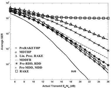
Figure 2.5 Performance comparison of different MUD approaches, 8 users, 4 channel paths/user, BPSK, equal transmit power for all users... 23
Figure 3.1 Centralized Channel Model... 24
Figure 3.2 Decentralized Channel Model ... 26
Figure 3.3 Diagram of THP for a Centralized-Channel (CC) System ... 28
Figure 3.4 Diagram of THP for a Decentralized-Channel (DC) System ... 33
Figure 3.5 Symbol error rate for user 1 of a 2-user system in AWGN channel, M-PAM, A1=A2, R12 = 0.5. ... 39
Figure 3.6 THP-DC, DF-MUD, decorrelating precoding and decorrelating MUD in AWGN channels, 3 users, 8-PAM, A1=A2=A3, R12 = R13 = R23 = 0.8... 40
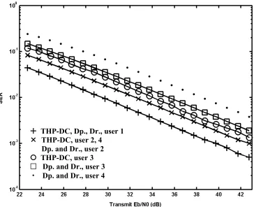
Figure 3.7 THP, decorrelating precoding and decorrelating MUD in Rayleigh fading channel, 4 users, 16-PAM, A12: A22: A32: A42 = 8:4:2:1, signal cross-correlation 0.8. ... 41
Figure 4.2 Transmitter of PreRAKETHP for a 2-user 2-channel path/user system ... 47 Figure 4.3 Transmitter of MDTHP for a 3-user N-channel paths/user system ... 51 Figure 4.4 Autocorrelation of Rayleigh fading signal, maximum Doppler shift 200Hz, 9 offset oscillators in Jakes model. ... 57 Figure 4.5 Performance comparison of various techniques in multipath fading channels, 8 users with equal transmit powers, 4 channel-paths/user, BPSK. ... 62 Figure 4.6 Performance comparison of various techniques, 8 users with equal transmit powers, 4 channel-paths/user, 16-QAM. ... 63 Figure 4.7 Best and poorest user SER for 8 users, 4 channel-paths/user, 8-PAM... 64 Figure 4.8 BER of the weakest user in large scale lognormal multipath fading channels, 4 users with equal transmit power, 3 channel paths/user, ratio of the received signal powers 8:4:2:1, BPSK. ... 65 Figure 4.9 Performance comparison of precoding aided by CSI prediction and by CSI feedback... 66 Figure 5.1 System Diagram of Closed-loop Transmit Antenna Diverisy ... 77 Figure 5.2 Transmitter diagram of PreRAKELDP for a 2-user, L-antenna System ... 79 Figure 5.3 Transmitter Diagram of MDP for a 2-user, L-antenna, N-channel paths/user system ... 89 Figure 5.4 The Structure of the lth branch in the MDP transmitter for a user,
Figure 5.6 Performance comparison of three space-time precoding methods, 8 users with equal transmit powers, 3 channel-paths/user... 93 Figure 5.7 Performance comparison of three space-time precoding methods, 1 to 12
users with equal transmit powers, 3 channel-paths/user, transmit Eb/N0=0dB. ... 94 Figure 5.8 Performance comparison of individual power scaling and total power
Chapter 1
INTRODUCTION
1.1 Background
Wireless communication is dramatically changing our lives. The ability to communicate anytime and anywhere increases our quality of lives and improves our business productivity. In cellular wireless systems, the network consists of numerous mobile users communicating with one or multiple base stations (BS) that are interconnected with a mobile telephony switching office. Originated from the spread-spectrum techniques, the code-division multiple access (CDMA) systems can support simultaneous digital communication among a large community of relatively uncoordinated users. CDMA exhibits potential capacity increase over the conventional time-division multiple access (TDMA) and frequency-division multiple access (FDMA), because CDMA capacity is only interference limited, while TDMA and FDMA are primarily bandwidth limited [GJP91]. The inherent frequency diversity of wideband signals enables CDMA to efficiently suppress the narrow-band interference in radio link. Direct sequence (DS) CDMA has been widely applied in the second and third generations cellular standards (IS-95, WCDMA and CDMA2000). It is also a very promising option for the next generation wireless communications.
rejection techniques have been developed. This research has primarily focused on receiver (Rx)-based multiuser detection (MUD) [Ver98] that results in a complex receiver while the transmitter remains simple. Thus, MUD techniques are mostly suitable for the uplink. For the downlink CDMA channel, the requirements of small-size low-power mobile station (MS) have motivated the development of Tx-based MAI pre-rejection techniques in BS, termed multiuser precoding. In addition to Tx-based MAI cancellation, Tx-based diversity techniques also efficiently improve system capacity. For frequency-selective fading channels, to simplify the mobile user receivers, the transmitter (Tx)-based PreRAKE combining is more suitable for the downlink than the conventional RAKE receiver [EN95]. This technique can utilize multipath diversity as efficiently as RAKE receiver. The Tx-based antenna array is another efficient diversity technique to increase the received signal to noise ratio [BZP04, GD05]. In the practical design of multiuser precoding techniques, the problems of MAI rejection, transmit power control and diversity strategies need to be considered comprehensively.
fading channel environment, and can only be viewed as flat fading non-orthogonal CDMA channels. The THP designs for frequency-selective fading channels are presented in [LD04, LDg04, LDj04]. In this thesis, we first illustrate the principle of THP for the simple case of single-path channels with additive white Gaussian noise (AWGN) and flat Rayleigh fading channels. Then we develop two specific THP designs for frequency-selective fading channels, THP with PreRAKE combiner (PreRAKETHP) and Multipath Decorrelating THP (MDTHP). The PreRAKETHP and MDTHP incorporate Tx-based diversity combining techniques in different ways. In PreRAKETHP, the MAI cancellation is followed by the pre-RAKE combining [EN95]. While this precoder is the optimal THP design for multipath channels, it requires high computational complexity, since its MAI cancellation filters depend on the rapidly time variant mobile radio channel coefficients and need to be updated frequently. In MDTHP, the diversity combining is incorporated into the MAI cancellation, and the precoding filter is independent of the channel. Thus, MDTHP is simpler than PreRAKETHP, and results in moderate bit error rate (BER) loss.
respectively, under the condition that the transmit power of individual user is not specified. In the MDP transmitter, the multipath diversity combining is incorporated into the MAI cancellation process, and the decorrelating filter is independent of the channel fading coefficients and only determined by users’ signature sequences. As a result, the computational complexity of the MDP is lower than that of the PreRAKELDP, Pre-RDD and the precoders in [VJ98, BD00].
Compared to the existing Tx-based and Rx-based linear decorrelating methods, the PreRAKELDP with total power constraint has the best performance and highest complexity; the PreRAKELDP with individual power scaling has similar performance to the Pre-RDD and RDD; the MDP has identical error rate to the Rx-based Multipath Decorrelating Detector (MDD) [LD03]. The two proposed precoders outperform those in [VJ98, BD00, GDv03, Gun03].
1.2 Outline of the Thesis
The goal of this thesis is to investigate and compare the Tx-based and Rx-based decorrelating MAI cancellation methods, with the application of transmit diversity and long-range channel prediction. The thesis is outlined as follows:
Chapter 2 first describes the frequency-selective channel model of uplink CDMA, the linear and nonlinear (DF) decorrelating multiuser detection methods are then presented and their complexity and performance are compared.
From Chapter 3 to Chapter 5, we concentrate on the downlink CDMA channels. In Chapter 3, we first describe the centralized and decentralized channel model with single-path additive white Gaussian noise (AWGN) and flat Rayleigh fading. The THP designs for these centralized and decentralized channels are presented, respectively.
Based on the THP principle introduced for single-path channels, we develop the THP techniques for multipath channels in Chapter 4. By combining the THP algorithm with multipath diversity in different ways, we present the PreRAKETHP and MDTHP designs in detail. The duality between these THP methods and Rx-based DF methods is analyzed. We also briefly review the principle of LRP. The performance of THP aided by LRP is observed in simulation experiments.
Chapter 2
DECORRELATING MULTIUSER DETECTION FOR UPLINK CDMA
2.1 Frequency-selective Fading Uplink CDMA Channel Model
For the uplink of CDMA systems, MS transmit signals towards BS. Consider the uplink of a K-user DS/CDMA system with a set of pre-assigned normalized signature sequences si(t), i = 1, 2, …, K, where each sequence is restricted to a symbol interval of
duration T. The data symbol for the ith user in the nth symbol interval is denoted by bi(n). In
practical wireless environment, the transmit signals are corrupted by fading and additive noise. If the data symbol duration is much smaller than the channel coherence, the channel is slowly fading, implying that the channel characteristics can be estimated accurately. If signal bandwidth is greater than the channel coherence bandwidth, the signal is subject to different gains and phase shifts across the band, thus the fading is said to be frequency-selective [Pro01]. The practical CDMA channels are usually frequency selective, due to the large bandwidth of spread-spectrum signals. In this case, the received signal includes multiple versions of the transmitted waveform which are attenuated and delayed in time. The frequency-selective slow fading channel can be modeled by a tapped-delay line [Pro01]. Suppose there are N resolvable paths from each MS to the BS. In the nth transmit symbol
interval, ci,l(n) = αi,l(n)ejφi,l(n) represents the gain of the lth path component over the channel
between the ith user transmitter and the receiver, ∀i = 1,2,…,K and l = 0,1,…, N-1. In the
special case of Rayleigh fading, ci,l(n) is a complex Gaussian random process; equivalently,
distributed. Due to uncorrelated scattering assumption, the channel gains corresponding to different paths are statistically independent.
Suppose K users transmit a stream of 2M+1 data bits simultaneously, and their signals are received synchronously at the BS, then the equivalent low-pass received signal is
r(t) =
∑
n=−M M
∑
i=1
K
∑
l=0N−1
ci,l(n)bi(n)si(t−nT−lTc)) + n(t), (2.1)
where Tc is the chip duration and n(t) is a white Gaussian noise process with zero mean and
power spectrum density N0. From equation (2.1), it is seen that even if the spreading codes are orthogonal, due to multipath fading, in the received signal there is multiple access interference (MAI), including inter-user interference, inter-symbol interference (ISI) and inter-chip interference (ICI). When the chip interval Tc is much smaller than the symbol
interval T and the multipath delay spread Tm is on the order of a few chip intervals, the ISI
due to channel dispersion may be neglected [ZB96]. For synchronous channels with this assumption, (2.1) can be simplified by only considering a single symbol interval [0, T),
r(t) =
∑
i=1
K
∑
l=0N−1
ci,lbisi(t−lTc) + n(t), (2.2)
Where ci,l = ci,l(0) and bi = bi(0).
The data symbols of all users can be expressed as a vector b = [b1, b2,…, bK]T.
Suppose the data symbols are M-ary PAM modulated with the minimum Euclidean distance
2Ai, i.e., bi∈{−(M−1)Ai, −(M−3)Ai,…,(M−3)Ai, (M−1)Ai}, i = 1, 2,…, K. Define the signature
define the vector of delayed signature sequences, s(t) = [s1(t)T s2(t)T … sK(t)T]T, and the
correlation matrix of delayed signature sequences
R ≡⌡⌠
0
T
s(t)sT(t)dt, (2.3)
The channel gain vector for the ith user is defined as ci = [ci,0 ci,1 … ci,N-1]T; and for K
users, define KN-row, K-column matrix C as
C = diag
{ }
ci =
c1 0 0 … 0
0 c2 0 … 0
… … … … … 0 0 … … cK
, (2.4)
in which 0 = {0}N×1. The conjugate transpose of ci is ciH = [ci,0*, ci,1*,…, ci,N-1*]. Hence, the
conjugate transposed matrix of C is CH = diag{ciH}, which has K rows and KN columns.
2.2 Linear Decorrelating Multiuser Detection Techniques 2.2.1 RAKE Decorrelating Detector (RDD)
yK
Q
RAKE User 1
• • •
RAKE User K r(t)
y1
Q
Decorrelating Filter
Rc−1
• • •
bˆ1
bˆK
Figure 2.1 Decorrelating Detector (RDD) for a K-user N-channel paths/user system
The conventional RAKE receiver is optimal in the absence of MAI; therefore it can be employed for single-user systems. However, the RAKE receiver suffers from near-far effects in the presence of interfering signals received over independent fading channels [KS93]. Even with perfect channel tracking, the near-far problem imposes a fundamental limit on the performance of conventional RAKE receiver.
Assuming the BS can perfectly estimate the channel coefficients, the front-end of the RDD receiver consists of K RAKE combiners. The outputs are incorporated into a vector, y = [y1, y2,…, yK]T. The outputs of the RAKE MF bank are sampled at the end of each
symbol interval, and the resulting output vector y is composed of K elements, y1, y2,…, yK,
which are given by
yk = ⌡⌠
0
T
r(t)ckHsk(t)dt, k = 1, 2,…, K, (2.5)
where ck and sk(t) follow the same definitions as those in section 2.1. For all the K users, the
RAKE combining output vector can be expressed by
y = Rcb + n, (2.6)
where Rc ≡ CHRC is a K×K matrix. The element on the ith row jth column of Rc is
Rcij = ⌡⌠
0
T
si(t)cicjHsj(t)dt, ∀i, j = 1, 2,…, K. The noise vector n is zero-mean Gaussian with
autocorrelation matrix N0Rc. If y is filtered by Rc-1, the MAI can be cancelled,
Rc−1y = b + Rc−1n. (2.7)
For BPSK systems, the average transmit SNR per bit for the kth user is given by [Pro01]
γbk ≡ EN0bk = Ak 2
2N0, k = 1, 2,…, K. Therefore, the theoretical SER can be expressed in terms of
γbk,
= −
k k bk
k Q
Pe
, 1 c ] [
2 R
γ
, (2.8)
It is illustrated in [LV89] that the conventional decorrelating detector for single path signals provides optimum linear multiuser detector performance in the maximum-likelihood sense when the users’ energies are unknown. The RDD is a linear detector which do not
require knowledge of the user energies. If sˆ (i t) ≡
∑
l=0N-1
ci,lsi(t−lTc) is regarded as the ith user’s
signature waveform, the RDD has the structure similar to the conventional decorrelating detector; hence, the RDD should provide the optimum performance over all linear multiuser detectors for multipath signals of unknown energy.
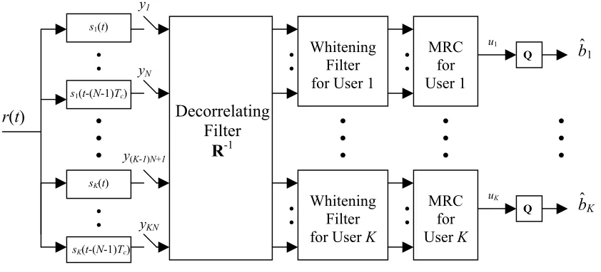
2.2.2 Multipath Decorrelating Detector (MDD)
y1
yN
• • • •
• • •
• •
uK
MRC for User K
•
• Q
Whitening Filter for User K
• •
u1
MRC for User 1
•
• Q
Whitening Filter for User 1
• •
• • •
• •
s1(t-(N-1)Tc)
• •
sK(t-(N-1)Tc)
sK(t)
yKN
y(K-1)N+1 s1(t)
r(t) Decorrelating
Filter R-1
bˆ1
bˆK
Compared to RDD, MDD is a simpler but suboptimal linear multiuser detector. As shown in Fig. 2.2, the front end of the MDD detector consists of KN correlators. Represent the KN outputs of the correlators by a vector, y = [y1, y2,…, yKN]T. Then y is given by
y = ⌡⌠
0
T
r(t)s(t)dt = RCb + n. (2.9)
n is the Gaussian noise vector with zero mean and autocorrelation matrix N0R. To eliminate
MAI, the decorrelating filter is defined as R−1. The decorrelated result is
v = R−1y = Cb + nv (2.10)
We know in the vector v = [v1, v2, …, vKN]T, every N elements correspond to one user, thus it
is convenient to define vk = [v(k-1)N+1, v(k-1)N+2, …, vkN]T, ∀k = 1, 2,…, K, then
v = [v1T, v2T,…, vKT]T. From equation (2.10), we have
vk = ckbk + nk , k = 1, 2,…, K, (2.11)
in which nk = [n(k-1)N+1, n(k-1)N+2, …, nkN]T. The autocorrelation matrix of nk is N0[R−1]k,k,
([R−1]i,j is the i,jth N×N block of R−1). Due to noise correlation among the N branches for the
kth user at the output of the decorrelating filter, the whitening operation is introduced prior to
combining. The whitening filter for the kth user Dk−T is obtained from Cholesky factorization
[GV96], [R−1]
k,k = DkTDk, ∀k = 1,2,…,K. The whitened result, denoted by vwk, is given by
vwk = Dk−Tvk = Dk−Tckbk + nwk , k = 1, 2,…, K. (2.12)
The whitened noise nwk = Dk-Tnk is zero-mean and Gaussian with the autocorrelation matrix
N0IN×N.
Although MRC is the optimal combiner, the noise-whitening process in MDD re-introduces the self-interference for every user, since the N branches of signal for each user becomes correlated when the noise components are whitened. This self-interference degrades system performance. Each element of the combined result, u = [u1, u2,…, uK], which is also the
decision variable for each user, equals
uk = (Dk−Tck )Hvwk = ckH ([R−1]k,k)−1ckbk+ ckHDk−1nwk, k = 1, 2,…, K. (2.13)
We can calculate that the noise component for user k is white Gaussian with power
N0ck([R−1]k,k)−1ckH. Hence, the instantaneous BER for user k can be expressed in terms of γbk,
Pek = Q
(
2ckH([R−1]k,k)−1ckγbk)
, k = 1, 2,…, K. (2.14)It has been mathematically proved that the performance of RDD is better than MDD (see Appendix of [HS94]). On the other hand, MDD has lower complexity, since the KN×KN
matrix inversion for MDD is not dependent on the channel coefficients and only need to be done when the set of active signature waveforms changes; while RDD require the inversion
of the K×K matrix Rc during almost each symbol interval because the matrix is dependent on
2.3 Decision-Feedback Decorrelating Multiuser Detection Techniques
For single-path channels, the nonlinear DF decorrelator achieves better performance than linear decorrelator [Due93]. Similarly, we will see that in the case of multipath channels, the DF approaches outperform the linear decorrelators discussed above. In section 2.3, we will discuss the two DF MUDs which employ the same MF structure as RDD and MDD, respectively.
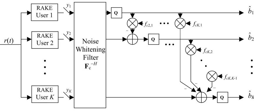
2.3.1 RAKE Decorrelating Decision-Feedback Receiver (RDDFR)
RAKE
User 1
RAKE
User 2
RAKE
User K
r(t)
Q
_ _ _
fcK,K-1
• • • • •
fcK,2
fcK,1
• • •
Q
_ fc2,1
yK
y2
y1
Q
Noise Whitening
Filter Fc−H
• • •
bˆ1
bˆ2
• • •
bˆK
Figure 2.3 RAKE Decorrelating Decision Feedback Multiuser Receiver (RDDFR) for a
K-user N-channel paths/user system
factorization, we obtain Rc = FcHFc, in which Fc = {fci,j}K×K is an upper triangular matrix. In
the proposed RDDFR detector, following the RAKE MF bank is a noise-whitening feed-forward filter, as shown in Fig. 2.3. The output vector of the filter Fc-H is equal to
y ~ = F
c−Hy = Fcb + z, (2.15)
where vector z = [z1, z2,…, zK]T = Fc−Hn. As shown in section 2.2.1, the autocorrelation
matrix of n is N0Rc. Consequently, the autocorrelation matrix of z is N0I, that is, the noise is
whitened by the feed-forward filter.
Similar to the DF MUD for single-path channels, in order to reduce the error propagation effect, we assume the K users are ordered according to their transmit signal power, i.e., user 1 is the strongest and user K is the weakest. Define the feedback filter as
B = Fc −diag(Fc), (2.16)
which is a lower triangular matrix with all-zero diagonal. As shown in Fig. 2.3, first the symbol of user 1 is estimated. From equation (2.15), we know the feed-forward filter output
for user 1 is ~y1 = fc1,1b1 + z1. Hence, the decision variable for user 1 should be fc1,1-1 ~y1.
Suppose the estimated symbol corresponding to b1 is denoted by bˆ1. For user i, i = 2, 3,…, K,
the decision variable is fci,i-1( ~yi −
∑
j=1i-1
fci,jbˆj + zi ). If define a vector bˆ = [ bˆ1, bˆ2 ,…, bˆK]T, the
decision device inputs for all K users can be expressed by
It is seen that the system performance is degraded by error propagation, which is reflected by the second term in equation (2.17). The ideal SER can be obtained by assuming there is no
decision error, i.e., bˆ = b. For the kth user, k = 1, 2,…, K, the ideal BER is
Pek = Q
(
2fck,k2γbk)
. (2.18)Now we compare the theoretical performance of the nonlinear RDDFR and that of the
linear RDD given by equation (2.8). Note that Rc−H=Fc−HFc−1 and therefore
(Rc−1)kk ≥ [(Fc−1)kk]2 = fckk−2 ((Rc−1)kk = [(Fc−1)kk]2 is satisfied only when k = 1). Thus the ideal
RDDFR outperforms the RDD (the optimal decorrelating linear MUD) for all users k > 1; for the first user, these two methods have the same theoretical performance. Since it has been proved in [HS94] that the RDD outperforms the MDD, the RDDFR also outperforms MDD theoretically. With the analysis similar to that for the optimality of the RDD, it is easy to conclude that the ideal RDDFR is the optimal decorrelating decision-feedback MUD. However, the practical performance of RDDFR is degraded by the error propagation effect. Similar to the DF MUD for AWGN channels [Due93], the error propagation effect can be mitigated by ordering the users from the strongest to the weakest.
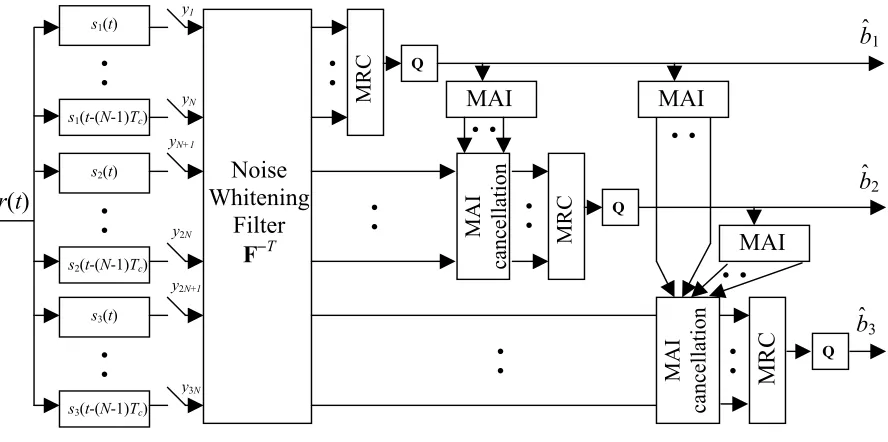
2.3.2 Multipath Decorrelating Decision-Feedback Receiver (MDDFR)
The MDDFR was proposed in [SK97]. In this method, the KN correlators are employed at the front end of the receiver in the same way as for MDD in Fig. 2.4, the output of the correlators is given by equation (2.9). From the definition of R in equation (2.3), it can be observed that R is symmetric and positive definite. Thus by Cholesky factorization, R = FTF, in which F = {fij}KN×KN is a real lower triangular matrix. As shown in Fig. 2.4,
F−Ty = FCb + nw, (2.19)
where nw = (FT)−1n is a zero-mean white Gaussian noise vector.
Divide the NK×NK matrix F into K2 square blocks, each block is an N×N matrix; and
represent the block on the ith row jth column by [F]i,j . The maximal-ratio combining (MRC)
is performed for user 1 first. The first N branches of the whitening filter outputs are filtered by c1H[F]1,1T, thus the input to the decision device for user 1 is
v1 = c1H[F]1,1T [F]1,1c1b1 + z1, (2.20)
where z1 is the noise component. The symbol decision for user 1, denoted by b^1, is fed back to the remaining users to help to cancel the MAI due to user 1. In this way, using the channel coefficients (which are assumed to be perfectly known at the base station) and the decisions
of the previous k−1 users, the MAI cancellation and MRC for user k, k = 2, 3,..., K, is performed as
vk = ckH([F]k,k)T
∑
i=1k−1
[F]k,ici(bi −bˆi) + ckH([F]k,k)T[F]k,kckbk + zk , (2.21)
where bˆi is the symbol decision corresponding to bi. Similar to the decorrelating DF MUD for
single-path channels [Due93], to minimize error propagation, the K users should be sorted from the strongest to the weakest, i.e., the first user should be the one whose signal has the strongest power, and the last user is the weakest one. By assuming no error propagation, we can obtain the ideal SER
The MDDFR is a suboptimal MUD even if the error propagation effect is ignored. An intuitive explanation is that the KN correlators at the front end of receiver are not the matched filters perfectly matched to the multipath fading channels. The theoretical performance comparison between the MDDFR and the optimal RDDFR follows the same derivation as in the comparison between the PreRAKETHP and MDTHP, which is provided in section 4.3.2.
Although the error rate of the MDDFR is higher than that of RDDFR, it should be noted that MDDFR has the advantage of low computational complexity, since the operation of matrix factorization is made on R, which is independent of channel state information.
The nonlinear MDDFR is closely related to the linear MDD, noticing that they have the identical front-end correlator bank. Compare the decision statistic of MDTHP, ckH[F]kkT[F]kkck, with that of MDD, ckH([R-1]kk)-1ck. Based on the theorem for the inverse of a
partitioned symmetric matrix [HJ85], it is easy to prove that ckH[F]kkT[F]kkck≥ ckH([R-1]kk)-1ck
bˆ1
yN+1
MAI
• • •
• MA
I
cancellation
• •
Q
MRC
• •
• • • •
M
A
I
cancellation
Q
MRC
MAI
bˆ2
bˆ3
MAI
• • • •
• •
s2(t-(N-1)Tc)
s2(t)
y2N
Q
MRC
• •
s3(t-(N-1)Tc)
s3(t)
y3N
y2N+1
• •
s1(t-(N-1)Tc)
s1(t)
r(t)
yN
y1
Noise Whitening
Filter F −T
2.4 Numerical Analysis
SUB
⋅ – ⋅ RDDFR RDD … MDDFR
ο MDD
× RAKE
Chapter 3
TOMLINSON-HARASHIMA MULTIUSER PRECODING (THP) FOR
SINGLE-PATH CHANNELS
3.1 THP for Single-path AWGN Channels 3.1.1 Single-path Centralized Channels (CC)
Rx Noise
CHANNEL Tx
Figure 3.1 Centralized Channel Model
The system diagram of CC model is shown in Fig. 3.1. In the CC model, both the transmitter and the receiver are centralized for all users (or all sub-channels in multi-channel systems), which make it possible to perform the Tx-Rx joint optimization with balanced complexity for the transmitter and receiver. The CC model with MIMO DF detector has been applied in multicarrier [VCLM98], space-time [LP02, ANC01] and other MIMO systems [Due92].
For a K-user system, denote the transmit data symbols during the symbol interval of interest [0, T) by a vector b = (b1, b2, …, bK)T. For high-speed downlink CDMA channels, the
improved without increasing MAI [TSG01, BBG00]. In this chapter, we use pulse amplitude modulation (PAM) as an example in derivation, while quadrature amplitude modulation (QAM) is also considered in numerical experiments. Suppose the symbols are M-ary PAM modulated with the equivalent baseband minimum Euclidean distance 2Ai, i.e.,
bi∈{−(M−1)Ai, −(M−3)Ai, …, (M−3)Ai, (M−1)Ai}, ∀i = 1, 2, …, K. Let the vector of
normalized signature waveforms for K users be s(t) = [s1(t), s2(t), …, sK(t)]T. For the CC
systems, the equivalent low-pass received signal at the centralized receiver is
r(t) =
∑
i=1
K
bisi(t)+n(t). In the conventional receiver, r(t) is fed to the filters matched to the K
users’ signature waveforms. The resulting output is yi=⌡⌠
0
T
r(t)si(t)dt, i = 1, 2, …, K. If we
define the correlation between two signature sequences as Ri, j=⌡⌠
0
T
si(t)sj(t)dt,
∀i, j = 1, 2 ,…, K, and the K×K correlation matrix R = {Ri,j}, the matched filter (MF) output
vector y = [y1, y2, …, yK]T satisfies
y = Rb + n. (3.1) In equation (3.1), n=[n1, n2, …, nK]T is a zero-mean Gaussian noise vector with the elements
ni = ⌡⌠
0
T
n(t)si(t)dt, i = 1, 2 ,…, K, and the autocorrelation matrix N0R. Note that we retain the
3.1.2 Single-path Decentralized Channels (DC)
As shown in Fig. 3.2, the DC model corresponds to the downlink of CDMA systems. In this channel model, the transmitter is centralized; the receivers of different users are separate, resource-constrained and do not have the knowledge of spreading codes of other users. Therefore, the processing burden is placed in the transmitter.
Rx Rx
Rx Tx
Noise
CHANNEL
Figure 3.2 Decentralized Channel Model
For the DC model, e.g., the downlink of a CDMA system, the equivalent low-pass
received signal at the ith receiver is ri(t) =
∑
i=1K
bisi(t)+ni(t) , where ni(t) represents white
Gaussian noise with zero mean and power spectrum density N0. In the ith user’s receiver, ri(t)
is fed to the filter matched to si(t). The resulting output is yi=⌡⌠
0
T
MF output has the same form as equation (3.1), but for DC model the autocorrelation matrix of n is N0I. (I is the K×K identity matrix.) In practice, these channels are not degraded by
MAI due to the orthogonal signature sequences and synchronous transmission, and thus, do not require Tx precoding. However, as in [VJ98, TC94], we employ this simple model with non-orthogonal users’ codes to illustrate the general principle of multiuser THP precoding. 3.1.3 THP for Centralized Channel (THP-CC)
From equation (3.1), we observe that MAI is caused by the non-diagonal elements of matrix R. For CC systems, as well as for the uplink of DS-CDMA, the interference can be conveniently canceled by the linear decorrelating MUD [Ver98] The output is R-1y =b+z.
Since the linear MUD enhances noise, the nonlinear DF-MUD was proposed in [Due93]. The positive definite symmetric matrix R is decomposed by Cholesky factorization [GVL96],
R = FTF, (3.2)
where F is a lower triangular matrix. For DF-MUD, a nonlinear feedback loop and a feed-forward filter are used to cancel the partial MAI expressed by F and FT respectively. This
approach avoids noise enhancement and outperforms linear decorrelating method; however, because the feedback is based on past decisions, the performance is degraded by error propagation.
Fig. 3.3 shows the system diagram of THP-CC. The feedback filter in the transmitter is defined as
BCC = {Bij}K×K = diag(F)-1×F−I, (3.3)
where F is as in equation (3.2), and diag(F)-1 = diag(F-1) is the diagonal matrix that contains
diagonal. A bank of mod-2M operators are used to limit the transmit power. For user i, given
an arbitrary real input β, the output of the mod-2M operator β~ satisfies β~/Ai = β/Ai + 2Mdi,
b1
Q
Q
• •
s2(t)
Mod-2M • • • Q Decision Device
sK(T-t)
s2(T-t)
s1(T-t)
yK y2 y1 • • • Mod-2M • • • Mod-2M Feed- Forward Filter GCC n(t)
Mod-2M
r(t)
x(t)
Channel v2 _ bK b2 • • • •
• vK
• • •
sK(t)
• • •
s1(t)
• • v1 Feedback Filter BCC
(a) Transmitter (b) Receiver
Figure 3.3 Diagram of THP for a Centralized-Channel (CC) System
where di is the integer to render β~/Ai within (−M, M]. In Fig. 3.3(a), the output vector of the
mod-2M operator bank v = [v1, v2, …, vK]T satisfies
v = b−BCCv+2MAd = (BCC+I)−1(b+2MAd), (3.4)
where A = diag{Ai}K×K and d = [d1, d2, …, dK]T is an integer vector. For the ith user,
i = 1, 2, …, K, di is chosen to guarantee vi in the range (−AiM, AiM]. Equation (3.4) is
ones along the diagonal. Thus, v1=b1 and d1=0, i.e., mod-2M is not required for user 1; for the
ith user, i = 2, 3, …, K, we can successively determine di and vibased on the values of v1,
v2,…, vi-1,
(3.5)
. 2
) ( 1
1
i i i
j j ij i
i b B v MAd
v = −
∑
− +=
The feedback structure is similar to that of DF-MUD. However, because the feedback in the transmitter is based on the actual values of user data instead of past decisions, error propagation is avoided.
The received signal is r(t) = sT(t)v+n(t). In Fig. 3.3(b), the output vector of the MF bank, y = [y1, y2, …, yK]T, is
y = Rv + n. (3.6)
Given (3.3) and (3.4), equation (3.6) is equivalent to
y = FTdiag(F)(b+2MAd) + n. (3.7) To recover the original data b, the feed-forward filter should be defined as
GCC = diag(F)−1F−T, (3.8)
Where F−T = (F−1)T = (FT)−1, thus the output of GCC is
GCCy = b + 2MAd + zCC, (3.9)
where zCC = GCC n. Equation (3.9) shows that MAI has been completely eliminated at the
whitened. The average transmit signal to noise ratio (SNR) per bit for the ith user, γbi, equals
[Pro01]
γbi ≡ EN0bi = (M 2 –1)A
i 2
6N0log2 M , i = 1, 2, …, K. (3.10)
Then the theoretical symbol error rate (SER) is
Pei = 2(MM Q-1)
6log2M
M 2-1 fii2 γbi , i = 1, 2, …, K, (3.11)
where fii is the ith diagonal element of F. The SER given by (3.11) is identical to that of
DF-MUD assuming no error propagation. It is observed that the order of users affects performance. For the first user, the ideal performance of THP equals that of the linear decorrelating MUD; for the last user, the ideal SER achieves the single user bound (SUB) since fKK = 1.
Note that in the transmitter the mod-2M operator output vi is in the range (−AiM,
AiM], which is larger than the range of original signal bi, [−Ai(M−1), Ai(M−1)], i.e., the signal
power reduced by modulo operation is still larger than the original signal power. This power
penalty diminishes as M increases and can be ignored for large M (M≥8) [LM94]. It also
3.1.4 THP for Decentralized Channel (THP-DC)
The scheme proposed in the previous section can be applied in DC systems by using adaptive linear processing in the receivers. However, it is often desirable to make the receivers of DC systems (e.g. the mobile stations in downlink CDMA) as simple as possible. Therefore, in this section we propose a different THP design in which the receivers are as simple as in a single-user system. The diagram of this design is shown in Fig. 3.4. The relocation of the feed-forward filter from the receiver to the transmitter causes the changes in the structures of the feedback and the feed-forward filters denoted by BDC and GDC,
respectively. The signal received at the ith user’s receiver site can be expressed as
ri(t) = sT(t)GDCv+ni(t). With transmitter precoding, the output vector of the scaled MF bank is
y = diag(F)-1(RGDCv + n) = diag(F)-1[FTFGDC(BDC+I)-1(b+2MAd) + n]. (3.12)
Although the scaled MF in the ith user receiver needs the knowledge of fii, this requirement
does not significantly increase receiver complexity. To cancel MAI, we define BDC and GDC
as
BDC = diag(F)-1FT−I, (3.13)
GDC = F-1. (3.14)
From (3.13), the feedback filter BDC is now upper triangular with zeros along the diagonal.
Thus the computation of the elements of v is in the reverse order relative to CC systems, i.e.,
vK = bK and dK = 0 (the mod-2M operation is not required for the last user). For
i = K-1, K-2,…, 1, vi=(bi −
∑
j=i+1K
Bijvj)+2MAidi. It can be shown that the feed-forward filter given
Substituting (3.13) and (3.14) into (3.12), we obtain y = b+2MAd+zDC. Mod-2M
operations are then applied to eliminate the term 2MAd. The noise component zDC = diag(F)-1n is whitened since its autocorrelation matrix is N0diag(F)-2. The ideal SER of
THP-DC is also given by (3.11).
11 1( )
f t T s − 1 ,1 1( )
− − − − K K f t T s KK K f t T s(−)
Q Q • • • • • •
r1(t)
K rK-1(t)
nK(t)
nK-1(t)
n1(t)
Mod-2M Mod-2M
rK(t) yK
yK-1
y1
Q
• •
x(t)
sK(t)
sK-1(t)
• •
s1(t)
• • Mod-2M Mod-2M vK-1 _ bK
bK−1
• • • • vK • • _ • • v1 Feedback Filter BDC b1 Feed- Forward Filter GDC Channel
(a) Transmitter (b) Receiver
3.2 THP for Flat Rayleigh Fading Channels
In this section, we extend the THP approach to flat Rayleigh fading channels. In the
symbol interval of interest, the channel gain for the ith user is denoted as ci = αiejφi, where the
envelope αihas Rayleigh distribution and the phase φi is uniformly distributed over (−π, π],
i = 1, 2, …, K. Define the channel gain matrix for K users as C = diag{ci}K×K.
For the DC system, the signal received at the ith user receiver is ri(t) = cisT(t)v+ni(t).
With the THP-DC, the output vector of the MF bank equals
y = CRv+n = Cdiag(F)(b+2MAd)+n. (3.15) The received signals are detected coherently, scaled and passed through the mod-2M
operators. The input of the detection device in the ith user receiver is αifiibi + ni. The average
SNR per bit at the input of the detection device γbi has the mean
{ } log 6 ) 1 ( 2 2 0 2 2 2 i i ii bi E M N A f M α
γ = − , i = 1, 2, …, K. (3.16)
For the ith user, the average SER is given by [Pro01]
+ − − − = bi bi i M M M M M Pe γ γ ) (log 3 1 ) (log 3 1 1 2 2
2 . (3.17)
For the CC model over the Rayleigh fading channel, the received signal is
r(t) =
∑
i=1
K
civisi(t) + n(t). The MF bank in the receiver is followed by the diagonal matrix CH,
resulting in the output y = CHRCv + CHn. Define Fˆ = FC, which is also a lower triangular
matrix, then the feedback and feed-forward filters are the same as (3.3) and (3.8) except that
white noise vector with auto-correlation matrix N0diag(F)−2C−2. Thus, the mean of average
SNR per bit at the detector input and the average SER are still given by (3.16) and (3.17), respectively.
3.3 Numerical Results and Analysis
In this section, we provide the numerical evaluations of the performance of THP designs for single-path channels. In the first numerical experiment, consider the downlink of a 2-user M-PAM CDMA system over an AWGN channel. Suppose the transmit powers of the two users are equal and the two signature sequences have cross-correlation R12 = 0.5. For user 1, the theoretical SERs of THP (both THP-DC and THP-CC), linear decorrelating MUD and linear decorrelating precoding are equal in this case. In Fig. 3.5, we demonstrate the difference between the simulation result for THP-DC and the theoretical SER. The gap between the theoretical and the simulated SER is caused by the “end effect” of mod-2M operation in receiver and the transmit power increase due to mod-2M operation in transmitter. The “end effect” diminishes as M or the transmit SNR increases. The transmit power penalty is reduced as M increases and is not related to the original transmit SNR. In this example, as M = 2, 4, 8, 16, the corresponding power penalty for user 1 are 0.67dB, 0.08dB, 0.03dB and 0.006dB, respectively. In this case, the performance degradation due to mod-2M operation is negligible for 8-PAM systems with transmit SNR larger than 20dB, and for 16-PAM systems.
Then we consider another example of a heavily loaded 3-user 8-PAM system over an AWGN channel. The cross-correlation between any two users is 0.8. All users have equal powers. Fig. 3.6 shows the performance of four methods: THP-DC, linear decorrelating transmitter precoding (Dp.), DF-MUD, and linear decorrelating MUD Receiver (Dr.). The performance of THP-CC (not shown) is very close to that for THP-DC. The only difference
in the THP-DC system and users 2 through K in the THP-CC system. The SUB and the conventional system performance are also plotted for comparison purposes. We notice that the linear decorrelating methods have the same performance for all users because of equal transmit powers and equal signal correlations. For THP-DC, the simulation results are very close to the theoretical performance since the end effect of mod-2M is slight for 8-PAM system. User 3 benefits the most from using THP. The THP achieves the SUB and has much lower error rate than DF-MUD and the linear methods. The worst performance is for user 1 and is theoretically the same as that of DF-MUD for user 1 and the linear methods for all users. For user 2, THP-DC outperforms the linear methods and DF-MUD. Clearly, the THP schemes improve on the linear schemes for most users. Although THP methods and DF-MUD achieve the same performance theoretically, the actual performance of THP is better than that of DF-MUD in this case since the latter technique suffers from error propagation when user powers are similar.
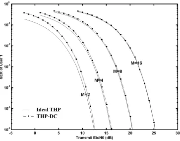
We now investigate a 4-user, 16-PAM system in a flat fading channel. Assume the channel gains are i.i.d. Rayleigh fading, and the power of channel fading is normalized. Let the signal cross-correlation between any two users be 0.8, and A12: A22: A32: A42 = 8:4:2:1.
Ideal THP −− THP-DC
Figure 3.5 Symbol error rate for user 1 of a 2-user system in AWGN channel, M-PAM,
Ideal THP
⋅ – THP-DC, user 1 THP-DC, user 2 THP-DC, user 3 Dr. & Dp., all users DF-MUD, user 1,3
DF-MUD, user 2
THP-DC, Dp., Dr., user 1 THP-DC, user 2, 4 Dp. and Dr., user 2
THP-DC, user 3 Dp. and Dr., user 3 Dp. and Dr., user 4
Chapter 4
TOMLINSON-HARASHIMA MULTIUSER PRECODING (THP) FOR
MULTIPATH FADING CHANNELS
4.1 Frequency-selective Fading Downlink CDMA Channel Model
Consider the downlink channel of a K-user DS-CDMA system. Suppose the transmitted signals are subject to frequency selective slow fading with N resolvable multipath components for every user. By assuming that the multipath spread is small relative to the symbol duration, the inter-symbol interference (ISI) is minor and ignored in the following
discussions. For user i, ci,n = αi,nejφi,n represents the gain of the nth path component, ∀i = 1,2,…,K and n = 0,1,…, N−1. The received equivalent baseband signal at the ith mobile
user receiver site can be expressed by
ri(t) =
∑
k=1K
∑
n=0N-1
ci,nbksk(t−nTc) + ni(t), (4.1)
where bk is the data symbol for the kth user in the symbol interval [0,T), sk(t) is the signature
sequence for the kth user, Tc is the chip duration, and ni(t) is complex white Gaussian noise
with zero mean and variance N0. Define the channel gain vector for the ith user ci=[ci,0,ci,1,…,ci,N-1], the column vector of datasymbols for all K users b=[b1,b2,…,bK]T, and
the diagonal matrix A=diag{A1,A2,…,AK}.
normalization factor Si ≡
∑
n=0
N-1
| |
ci,n2-1/2
, then the normalized fading coefficient is obtained by
cˆi,n ≡Si ci,n , and the normalized vector corresponding to ci is cˆi =
[
cˆi,0, cˆi,1,…, cˆi,N-1]
. For theconvenience of derivations, for all K users define a K-row, (K×N)-column channel gain
matrix C = diag{c1,c2,…,cK} and the corresponding normalized matrix
4.2 PreRAKE Multipath Diversity Combining
b1
∑
*
0 , 1
ˆ
c
×
* 1 , 1
ˆ
c
×
* 1 , 1 ˆ −
×c N
r(t)
• • •
• • •
single user MF
Decision Device
y1
spread with s1(t-(N-1)Tc)
spread with s1(t-(N-2)Tc)
spread with s1(t)
multipath channel x(t)
Figure 4.1 Diagram of PreRAKE System, single user, N resolvable channel paths
For direct-sequence spread spectrum (DS-SS) communications (single-user systems), RAKE receiver is known as the optimum maximum ratio combining detector, where signals of the individual paths are added in a way to accentuate more credible signals and suppress less credible ones. Compared to a single-path receiver, the RAKE combiner is more complicated and needs the instantaneous channel information for setting weighing factors. For the downlink channels, in order to minimize the mobile unit cost and power consumption, PreRAKE combiner was proposed in [EN93]. It concentrates all the processing required for the RAKE combination at the BS and keeps the mobile user receiver as simple as a non-combining single path receiver.
coefficients have to be known by transmitter. This information could be obtained by feeding it back from the receivers. However, the inaccuracy due to the delay of feedback has to be considered, especially when the channel fading changes fast. For rapidly varying fading channels, the channel information can be accurately predicted by the long-range channel prediction algorithm, which is illustrated in section 4.4.
The system diagram of a PreRAKE transmitter and receiver is shown in Fig. 4.1. In the transmitter, the spread signal is delayed and weighed for a number of times. The estimated channel path profile for future transmission is used to set the weighing factors. To illustrate the principle of PreRAKE combining, we only consider the single-user system in this section, i.e., suppose only user 1 is active. With PreRAKE combining, the transmitted signal is given by
x(t) =
∑
n=0
N-1
cˆ1,n*b1s1(t−N−1+nTc). (4.2)
After traveling through the N-path fading channel, the signal received at the receiver is
r1(t) =
∑
l=0
N-1
∑
n=0N-1
c1,lcˆ1,n*b1s1(t−(N−1−n+l)Tc) + n1(t) (4.3)
At the receiver end, the desired output of the PreRAKE combining system occurs at moment
t = (N−1)Tc. The receiver is a simple single path receiver which decodes only the (N−1)th
peak of the matched filter output for each transmitted symbol,
y1 = ⌡⌠
(N-1)Tc T+(N-1)Tc
r(t)s1(t−(N−1)Tc)dt = b1
∑
l=0N-1
∑
n=0N-1
c1,lcˆ1,n*⌡⌠
0
T
where n1 is the Gaussian noise component with zero mean and variance E{n1n1*}=N0. It can be observed from equation (4.4) that there is self-interference in the MF output caused by the multipath. The effect of self-interference on the PreRAKE performance is analyzed in [ESN99]. If the selected spreading sequence has very small auto-correlation, the self-interference can be ignored. With this assumption, the received SNR is given by
SNRRx = NEb
0
∑
n=0
N-1
c1,lcˆ1,n* = S1−1SNRTx, (4.5)
4.3 THP for Frequency-selective Fading Channels 4.3.1 PreRAKETHP
w1 *
0 , 1 ˆ
c
* 1 , 1 ˆ
c
* 0 , 2 ˆ
c
* 1 , 2 ˆ
c
× × ×
b1
x(t)
Spread with s2(t)
Spread with s2(t-Tc)
Spread with s1(t)
Mod-2M
v2
v1
Feedback Filter
BP
Feed Forward
Filter GP
_
b2
w4
w3
w2
Σ
Spread with s1(t-Tc)
×
Figure 4.2 Transmitter of PreRAKETHP for a 2-user 2-channel path/user system
The transmitter structure of PreRAKETHP for a 2-user 2-channel path/user system is shown in Fig. 4.2. The basic THP decorrelating structure is similar to that for the single-path case, and is followed by a pre-RAKE combiner. The FB and FF filters for PreRAKETHP are denoted by BP and GP, respectively. With the same derivation as for single-path channels, the
output vector of the mod-2M operator bank satisfies v = (BP+I)-1(b+2MAd). As we will see
later, BP is a complex matrix related to the channel fading; as a result, the inputs of the
mod-2M operators are complex numbers. The mod-mod-2M operations are performed to constrain the magnitudes of the real part and imaginary part of the input number respectively. Thus for the
ith user, di is a complex number with integral real and imaginary parts. As in Fig. 4.2, the
coefficients. The output vector of the pre-RAKE combiner, w = Cˆ HGPv, has K×N elements.
Following the signature sequence spreading, the ultimate transmitted signal is given by
. (4.6)
∑∑
= − = − − = K k N l c k lkN s t lT
w t x 1 1 0 ) ( ) (
The equivalent baseband received signal at the ith user receiver site is given by
. (4.7)
) ( ) ( ) ( 1 1 0 1 0
, w s t lT nT n t
c t
r K i
k N n N l c c k l kN n i
i =
∑∑∑
− − += −
= −
= −
The output of the MF is sampled at t = (N−1)Tc, and for the ith user is given by
. (4.8)
∫
− + − − − = c c T N T T N c i ii r t s t N T dt
y ) 1 ( ) 1 ( ) ) 1 ( ( ) (
The cross-correlations between delayed signature sequences can be represented as
( ) ( ) , m∈{−(N−1), …, (N−1)}. (4.9) 0 , =
∫
+ T c k i m ki s t s t mT dt
M
From (4.7), (4.8) and (4.9), we have
yi =
∑
k=1K
∑
n=0N−1
∑
m=−(N−1)N−1
ci,n Mim,k w(k-1)N+m+n+1 +ni , (4.10)
where ni is the filtered noise component with power N0. ∀i, k∈{1, 2, …, K}, define the N×N
correlation matrix Mi,k with the jth row equal [ , j=1, 2,…, N. Construct
the (K×N)-row and (K×N)-column matrix M by superimposing the K×K non-overlapping
submatrices M
] ,...,
, 2 ,
, 1 , j N k i j k i j k
i M M
M − − −
i,k, i, k∈{1, 2, …, K}. Then (4.10) reduces to
where y = [y1, y2, …, yK]T and n = [n1, n2, …, nK]T . Define RP ≡ CMCH and
RˆP ≡ S2RP = CˆMCˆH. The matrix RP is obviously positive definite. Consequently, it can be
factorized as FPHFP using the Cholesky factorization, where FP={fPij}K×K is complex lower
triangular matrix with real diagonal elements. The normalized matrix corresponding to FP is
Fˆ ={fˆ }ij K×K = SFP. To cancel the MAI, the FB and FF filters are defined as
BP≡diag(Fˆ )-1Fˆ H − I , (4.12)
GP≡ Fˆ-1. (4.13)
Then equation (4.11) can be simplified as
y = diag(FP)(b+2MAd) + n. (4.14)
We assume the channel gains and, therefore, fPii are estimated in the receivers. Then for the
ith user, we have fPii-1yi = bi + 2MAidi + fPii-1ni. The term 2MAidi will then be cancelled by
mod-2M operation. The instantaneous ideal SER of the ith user is given by
− −
= ii bi
i
M f M M
M
Pe γ
1 ) (log 6 ) 1 ( 2
2 2 P
2 (4.15)