ISOLATED WIND HYDRO HYBRID SYSTEM USING
BATTERY STORAGE FOR GRID FREE OPERATION
WITH FUZZY LOGIC CONTROLLER
Sonal Karambe
1, Dr. K. Vadirajacharya
21
M. Tech Student, Electrical Department ,Dr. Babasaheb Ambedkar Technological University ,(India)
2
Professor, Electrical Department, Dr. Babasaheb Ambedkar Technological University, (India)
ABSTRACT
This paper presents a Isolated Wind Hydro Hybrid System using permanent magnet synchronous generators, one is driven by variable speed wind turbine and other is driven by constant power hydro turbine. The proposed system utilizes two back to back connected VSC’s to improve the power quality of the system. Battery storage is
connected at their dc link to maintain the active power balance in the system. The proposed system is feeding three phase four wire load. Magnitude and frequency of the load voltage is maintained constant by this proposed system with the use of fuzzy logic controller .The System is simulated in MATLAB using Simulink and Sim power system set toolboxes. It has the capabilities of harmonic reduction.
Keywords— Battery Energy Storage System(BESS), Permanent Magnet Synchronous Generator
(PMSG),Voltage Source Converter (VSC
)
I INTRODUCTION
The dynamic behavior of the system depends on disturbance of the system. The quality of generated power in power system is dependent on the system output, which has to be of constant frequency and must maintain the scheduled power and voltage. Therefore, in order to provide reliable power with good quality, load frequency control is very important in power system [4]. The unsteady nature of wind and changing load demands frequently may cause large oscillation of power. These fluctuations of output power may cause a serious problem of frequency and voltage fluctuation of the grid. An effective controller should be provided for maintaining frequency of the system within acceptable range [2]. Therefore, a control system is required to detect the load changes and its mechanical power production and stabilize the system frequency [1]. The function of the load frequency controller is to eliminate a mismatch between generation and load created due to a change in input wind power. PI controller reduces steady state error to zero but it does not give best control for wide range of operating conditions as it is designed for normal operating conditions with fixed gains. It depends on the precise mathematical model and parameter settings are difficult as accurate mathematical model is not easy to obtain. Therefore, fuzzy logic control is used which is a intelligent control that uses fuzzy rule sets and linguistic representation of a human’s knowledge to control a plant [6]. The fuzzy logic technology has been widely applied in many control fields, and positive control effects have been obtained. Section II gives details about PMSG based wind hydro hybrid system. Section III Presents a control scheme for load side converter. Section IV explains about components fuzzy logic controller and fuzzy logic controller for load side converter. Section V gives the simulation model of wind hydro hybrid system using fuzzy logic controller and section VI discuss about simulation results.
II PMSG BASED WIND HYDRO HYBRID SYSTEM
A. Wind Turbines
The turbines can only operate within a very range above the synchronous speed, and this requires the turbine blades to rotate at a nearly constant speed. The turbine is used to convert wind energy into mechanical energy. a wind turbine can be built in either a vertical-axis or horizontal-axis configuration. Horizontal-axis wind turbines (HAWTs) dominate the utility-scale wind turbine market because they have aerodynamic and practical advantages [6]. Smaller vertical axis wind turbines (VAWTs) are more likely to use passive rather than active control strategies. Vertical axis wind turbine consists of several blades rotating about axis in parallel direction; the cycloid blade system and the individual active blade control system are adopted. Below the rated wind speed, the speed controller can continuously adjust the rotor speed to maintain the tip speed ratio constant at the level which gives the maximum power coefficient, so the efficiency of the turbine will be significantly increased. Pitch angle regulation is necessary in conditions above the rated wind speed when the rotational speed is kept constant which can have a dramatic effect on the power output.
B. Permanent Magnet Synchronous Generator
gap. Moreover, the smooth rotor surface design minimizes saliency in the rotor, contributing to a low armature reaction effect due to low magnetization inductance. Other is an Interior Permanent magnet machine which has the permanent magnets placed inside the rotor and used for high speed operation. The rotor is having alternate N and S poles.These magnets produces magnetic flux in the air gap. When the stator windings are excited, they produce their own magnetic flux and electromagnetic torque in the rotor is developed due to the interaction between rotor and stator magnetic fields.
C. Battery Energy Storage System
An integral part of autonomous system is Battery Energy Storage System. It is used for ensuring security, high level power quality and reliability. Energy storage can be electrochemical, mechanical, electromagnetic, thermal or hydrogen-based. Electrochemical energy storage includes lead-acid, lithium-ion, flow and sodium-sulphur batteries.The advantages of energy storage system are as follows
As the renewable energy sources are intermittent in nature, there will be the mismatch between generation and load. Therefore, energy storage system is used to match the output power of renewable energy source and load.
Energy storage systems can be used to provide reliable, high quality power to sensitive loads.
Energy is stored when the load demand is less than generation and it is transferred to the load during low wind speed conditions ensuring reliable operation.
III
CONTROL
OF
LOAD
SIDE
CONVERTER
The main aim of proposed approach is to regulate magnitude and frequency of load voltage. The inverter is actively controlled in such a way that it always draws or supplies fundamental active power from or to the grid. It also compensates harmonics if load is non- linear, unbalanced.
The actual dc-link voltage Vdc is sensed and passed through a first-order low pass filter (LPF) to eliminate the presence of switching ripples on the dc-link voltage and in the generated reference current signals. The difference of this filtered dc-link voltage and reference dc-link voltage Vdc* given to a fuzzy controller to maintain a constant dc-link voltage under varying generation and load conditions. The dc-link voltage error Vdcerr(n) at nth sampling instant is given as
Vdcerr(n)=V*dc(n)-Vdc(n) (1)
The regulation of dc-link voltage carries the information regarding the exchange of active power in between renewable source and grid. Thus the output of dc-link voltage regulator results in an active current.
The output of discrete-PI regulator at th sampling instant is expressed as Im(n) = Im(n-1) + Kpvdc (Vdcerr(n) - Vdcerr(n-1) +
KivdcVdcerr(n) (2)
The grid synchronizing angle (θ) obtained from phase locked loop (PLL) is used to generate unity vector template as
Ua = Sin(θ) (3)
The multiplication of active current component with unity grid voltage vector templates generates the reference grid currents as
I*a = Im . Ua (6) I*b = Im . Ub (7) I*c = Im . Uc (8)
The reference grid currents are compared with actual grid currents to compute the current errors as
Iaerr = I*a - Ia (9) Iberr = I*b - Ib (10) Icerr = I*c - Ic (11)
These current errors are given to hysteresis current controller. The hysteresis controller then generates the switching pulses (P1 to P6) for the gate drives of load side converter.
IV FUZZY LOGIC CONTROLLER
A fuzzy control system is a control system based on logical mathematical system that analyses analog input values in terms of logical variables that take on continuous values between 0 and 1, in contrast to classical or digital logic, which operates on discrete values of either 1 or 0. The Fuzzy Logic tool which was introduced by Lotfi Zadeh in 1965 emerged as one of the most active and fruitful areas for research in the application of fuzzy set theory [6]. In the systems using fuzzy logic techniques, operating conditions are monitored and used as an input to the fuzzy logic controller. The output signals of the fuzzy controller controls the input to the governor for increasing or decreasing the generation to maintain the system frequency. Fig. 1 shows Block Diagram of Fuzzy Logic Controller.
Input Madmani Output
Fig. 1 Block Diagram of Fuzzy Logic Controller
A. Components of Fuzzy Logic Controller
The fuzzy controller has four main components are as follows :
(i) the “rule-base” holds the knowledge, in the form of a set of rules, of how best to control the system
(ii) the inference mechanism evaluates which control rules are relevant at the current time and then decides what the input to the plant should be
(iii) the fuzzification interface simply modifies the inputs so that they can be interpreted and compared to the rules in the rule-base and
(iv) the defuzzification interface converts the conclusions reached by the inference mechanism into the inputs to the plant .
B. Advantages
It is more robust than other non- linear controllers.
It has a ability to deal with the systems that are non- linear or time varying, complex.
Fuzzy logic controller is used when mathematical formulations are not possible due to the lack of quantitative data of input output relations
C. Fuzzy Logic Controller for Load Side Converter
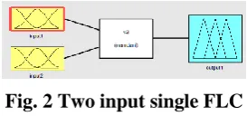
Fig. 2 shows FLC which has two inputs i.e output voltage error and its derivative and change in duty cycle as a output. Madmani fuzzy model is used for the fuzzy controller. The controller input has a fuzzy variable and these inputs are fuzzified with seven membership functions. Output variables are also defined with membership function.
Fig. 2 Two input single FLC
The Fuzzy variables are expressed by linguistic variables as positive large (PL), positive medium (PM), positive small (PS), zero (Z), negative small (NS)‟, negative medium (NM), negative large (NL), for all three variables. A rule in the rule base can be expressed in the form: If (e is NL) and (de is NL), then (cd is NL). The basic fuzzy sets of membership functions for the variables as shown in fig.3 and 4.The rules are set based upon the knowledge of the system and the working of the system. The rule base adjusts the duty cycle for the PWM of the inverter according to the changes in the input of the FLC is given in table 1.The number of rules can be set as desired. The numbers of rules are 49 for the seven membership functions of the error and the change in error (inputs of the FLC).
Fig. 3 Input variable 1
Fig. 4 Input variable 2
V
SIMULATION
MODEL
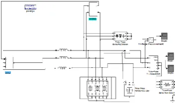
Model of Wind Hydro Hybrid System using fuzzy logic controller shown in fig. 6 is developed in MATLAB and simulated in MATLAB version 7.10 using Simulink and sim power system toolboxes. Wind power plant consists of generator, turbine, rectifier and inverter in which battery storage is connected at dc link. Simulation model of wind power plant is shown in fig. 7 and model of hydro power plant is shown in fig.8.
Fig. 6 Wind Hydro Hybrid System
Fig. 7 Simulink Model of Wind Power Plant
Fig. 8 Simulink Model of Hydro Power Plant
VI
SIMULATION
RESULTS
Fig. 9 Electromagnetic Torque and rotor speed of wind turbine
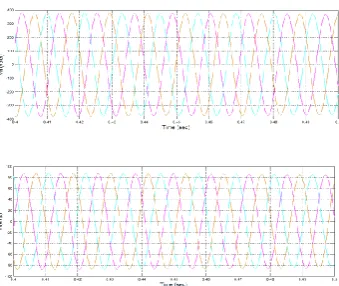
Fig. 10 Waveforms for Load Voltage and Load Current
Fig. 11 Hydro Generator Voltage and Hydro Generator Current
The waveforms obtained from Hydro power plant are shown in fig. 11. Table 2 shows THD contents for voltages and currents of hydro generator and load.
Sr. No. Voltage and Current THD (%)
1 Load Voltage 6
2 Load Current 4
3 Hydro Generator Voltage 7
4 Hydro Generator Current 9
VII CONCLUSION
A new three-phase four wire autonomous wind-hydro hybrid system is proposed for the locations where electricity is not easily available from the grid. A novel control is presented for load side converter to improve the power quality at the load side. The proposed system has been modeled and simulated in MATLAB using Simulink and Sim Power System tool boxes. The FLC is designed with Fuzzy Logic Toolbox and the simulations are performed in MATLAB using Simulink. Simulation results shows that the current harmonics are in the limits of international standards (<5%).
Fuzzy logic controller with seven membership function is used to obtain accuracy of the system. Moreover, it eliminates the voltage and current
harmonics with Fuzzy Logic Controller.
REFERENCES
[1] Bhim Singh, S. S. Murthy and Sushma Gupta “An Improved Electronic Load Controller for Self- Excited Induction Generator in Micro Hydel Applications”
[2] Dheeraj Joshi, Kanwarjit Singh Sandhu, and Mahender Kumar Soni,”Constant Voltage Constant Frequency Operation for a Self-Excited Induction Generator” IEEE Transactions on Energy Conversion, Vol. 21, NO. 1, March 2006
[3] G. Quinonez-Varela and A. Cruden, “Modelling and validation of a squirrel cage inductiongenerator wind turbine during connection to thelocal grid” IET Gener. Transm. Distrib., 2008, 2, (2), pp. 301–309 [4] Bhim Singh, Senior Member, IEEE, and Gaurav Kumar Kasal,”Voltage and Frequency Controller for a
Three-Phase Four-Wire Autonomous Wind Energy
[5] C.F.Nicy, R.Punitharaji ,G.Balaji, “Isolated Wind–Hydro Hybrid System using Permanent Magnet Synchronous Generators and Battery Storage with Fuzzy Logic Controller”, International Journal of Engineering Development and Research
[6] C.C.LEE, Fuzzy logic in control systems: fuzzy logic controller- part 1, IEEE Trans. Syst. Man Cybern., Vol. 20, No. 2, 1990, pp. 404-418.