Research on Efficiency Optimization of Rail Transit Wireless Power
Transmission System Based on Electromagnetic Detection
Yunzhi Lin1, * and Yixiong Lai2
Abstract—In the installation of a dynamic wireless power transmission system of rail transit, the distance change among coils causes large power loss under high power conditions. Due to the limitation of detection surface and Doppler effect as well as other deficiencies, the traditional ranging methods cannot be adapted to fast, continuous, and large-area dynamic ranging in the wireless power transmission of rail transit. Therefore, the paper proposes a single coil dynamic wireless power efficiency optimization method based on electromagnetic induction for the first time. The distance between the transmitter and receiver is taken as the intermediate quantity, and the relationship between the detection coil amplitude and the wireless power transmission efficiency is constructed. Firstly, based on electromagnetic field theory, a quantitative relationship among the detection coil amplitude, wireless power transmission efficiency, and coil distance is established. Then detection experimental platform is designed. Finally, relevant experiments are accomplished through the established experimental platform. The experimental results show that for the area with low power transmission efficiency on the whole dynamic wireless power transmission line, relevant ranging data can be obtained by detecting the amplitude.
1. INTRODUCTION
Wireless power transmission technology, hereafter referred to WPT, converts municipal electricity into high frequency AC through a converter, so that the transmitting coil on the ground generates alternating magnetic field with a specific frequency. The magnetic field is coupled to the receiving coil, and the alternating current is induced therein, which realizes WPT. The technology has gained rapid development in recent ten years. In electrified transportation, the wireless charging technology of rail transit has initially entered the practical stage.
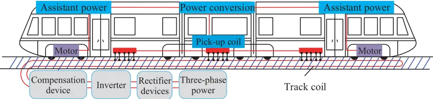
For a dynamic WPT system, transmission efficiency is an important index and is of vital significance for a high power system. The distance between transmitter and receiver is an important factor for system efficiency, but in the installation of transmitting coils, the change of roadbed, the difference of construction quality and the thermal expansion and contraction of materials will lead to the inconsistency of transmission distance between different locations on the whole line, thus it will affect the overall efficiency. Fig. 1 presents a typical dynamic wireless power supply system for rail transit.
At present, the main ranging methods suitable for engineering field include laser ranging, ultrasonic ranging, and electromagnetic testing.
Laser ranging [1, 2] refers to moving a laser beam from the initial position to the target and reflecting it back from the target. It is a method to determine the measurement distance based on the measurement time of the round trip of the emitted laser. Laser ranging plays an important role in military applications, engineering construction, science and technology, shipbuilding, as well as other
Received 7 September 2019, Accepted 19 November 2019, Scheduled 18 December 2019
* Corresponding author: Yunzhi Lin ([email protected]).
1 Department of Electrical Engineering, Tsinghua University, Beijing 100084, China. 2 Urban Railway Company of China CREC
Track coil
Motor Motor
Power conversion
Pick-up coil
Three-phase power Rectifier
devices Inverter
Compensation device
Assistant power Assistant power
Figure 1. Typical dynamic wireless power supply system for rail transit.
fields. Ultrasound ranging [3, 4] emits a certain frequency of ultrasound. When the acoustic wave encounters obstacles, it will produce reflected echo to compare the reflected echo with the emitted acoustic wave and measure the time difference. Then the distance is calculated according to the speed of the ultrasonic wave propagating in the medium. Electromagnetic ranging [5–8] emits electromagnetic waves modulated by alternating current from one end of the line and returns from the other end. The phase difference between the transmitted wave and the echo is measured by a phase discriminator, and the distance can be calculated according to the measured phase difference.
Laser ranging is not applicable in large area plane detection and dynamic detection, and it is greatly affected by rain and fog weather. Doppler effect exists in the detection of fast and dynamic moving targets by ultrasonic ranging method, which will result in larger detection errors. Therefore, based on the method of electromagnetic detection, the paper proposes to optimize the transmission efficiency of the system according to the amplitude, so as to adjust the distance between the receiving end and transmitting orbit. According to different transmission distances of the system, the efficiency of the system will change, and then the amplitude of the detection coil will change, so that the system efficiency of the whole line can be optimized. The proposal exerts an important guiding significance on the application of dynamic WPT system of rail transit.
2. WORKING PRINCIPLE OF DETECTION SYSTEM 2.1. System Efficiency
Figure 2(a) is the theoretical principle of WPT system. The factors affecting the transmission efficiency of the system in WPT include the distance between coils, the radius of coils, the number of turns between coils, and the frequency of the system. When transmitting and receiving coils share the same structure parameters and the same frequency, the influence of coil distance on transmission efficiency is mainly considered. The theoretical formulas under the SS-type topology are as follows [9–12].
When the structures of transmitting coil and receiving coils are the same, Rp = Rs = R. The
V
Load
C
pR
pL
pL
sR
sC
sR
LI
pI
sM
h r1
r2
(a) (b)
transmission efficiencyη of the system is expressed [13–16] as by formula (1).
η= 1
1 +
R+RL
ωM
2
R RL +
R RL
(1)
As shown in Fig. 2(b), the spacing between the two coaxial circular coils with radii of r1 and r2
respectively is d. We denote K =r1/r2, which is called the relative size, and denote j =d/r1, which
is called the relative distance. Since the mutual inductance M12= M21, the calculation of the mutual
inductance (M) is proven by the Biot-Savart law to be formula (2):
M = μ0r1 2 k 0 2π 0
x(1−xsinθ)
(x2−2xsinθ+ 1 +j2)3/2dθdx= μ0r1
2 I0 (2)
where in engineering design, K is controlled between 0 and 0.3. At this time, two terms xsinθ and x2
in formula (2) are omitted, easily resulting in the expression of mutual inductance as follows:
M = μ0r1
2 I ≈
μ0
2
πr2 1r22
2h2+r2 1
3/2 (3)
In formula (3), μ0 is the vacuum permeability; n is the turn number of coils; r1 is the radius of
detecting coils; r2 is the radius of excitation coils;h is the distance between coils.
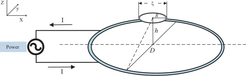
2.2. Principle of Electromagnetic Detection
The detection schematic given in Fig. 3 adopts a coil detection structure with single excitation and single reception. When sinusoidal alternating current is introduced into the excitation coil, alternating magnetic field is produced in space. The receiving coil can detect the changed electrical signals in space. However, due to different positions of the two coils, different electromotive forces are generated. According to the relationship between coil position and system efficiency in formula (1), the change of system efficiency is reflected by the amplitude, and the transmission efficiency of the system is tracked.
D Power h R ξ X y Z I I
Figure 3. System structure diagram.
According to the principle of electromagnetic induction, when the flux in the conductor changes with time, the corresponding electromotive force will be generated in the circuit of the inductive conductor [17–20], and the following formula holds:
E =−dϕ
dt =−N· d dt
s
− →
B ·d−→S (4)
In a constant magnetic field in space, the current in the transmitting coil is simplified to line current. According to Biot-Savart Law, the magnetic induction intensity of the transmitting line can be expressed as:
B= μ0 4π
l
Idl ×eR
|r−r|2 (5)
where|r−r|represents the distance between the field point and the original point,l the closed loop of the transmitting coil, andeRthe unit vector from the source point to the field point. Simplified results
are as follows:
B = μ0I
2π|r−r| (6)
In the formula, I is a current excitation signal, and the electromotive force in the coil is expressed as:
E =−iωBS=−iω
s
μ0I
π
D
2
2
+h2
ds (7)
The detection amplitude ξ is expressed as:
ξ =ω
s
μ0I
π
D
2
2
+h2
ds (8)
3. DESIGN OF SYSTEM DETECTION PLATFORM 3.1. Overall System Design
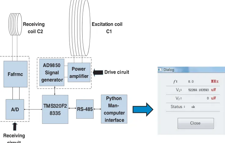
The schematic diagram of EMF detection system based on electromagnetic induction is shown in Fig. 4. It includes a class E power amplifier circuit combined with a DE150-501N04A signal generator
T TMS320F2 8335 RS-485 Python Man-computer interface AD98 50 Signal generator Fafrmc Excitation coil C1 Receiving coil C2 Drive ciruit Receiving circuit Power amplifier A/D
(transmitter) and a transmitting coil to provide excitation signal. The structure of single excitation, double coils is designed as the measurement model, which provides an experimental platform for the efficiency detection among coils. The output signal is amplified and smoothed by the single coils detection module (receiver). The data processing center based on TMS320F28335 is used to measure the magnitude and other information of the system, and the data are transmitted to Python human-machine interface through communication 485 interface to collect the experimental data. The technical principle and structure of the detection system are shown in Fig. 4.
3.2. Transmitter Principle
The transmitter employs a class E power amplifier circuit, which includes a power supply module, a data transmission module of receiving circuit, an output signal module of excitation coil, and a driving signal module. In electromagnetic detection, the transmitter provides the field source signal [20–22]. Transmitter is an important module of a detection system and the basis of a normal operation of the system. The design block diagram of a class E power circuit is shown in Fig. 5.
E power circuit Drive
signal
Power
Signal output
Data transmission
Figure 5. Design block diagram of transmitter circuit.
A picture of transmitter circuit of the system is shown in Fig. 6.
Figure 6. Real product picture of transmitter circuit.
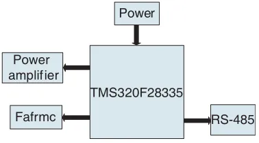
3.3. Theory Consideration of the Receiver
The receiving circuit consists of the following modules: power supply module, Fafrmc power amplifier module of the energizing circuit, and RS485 serial communication module. A TMS320F28335 DSP controller is used to control the whole circuit. The design diagram of system is showed in Fig. 7.
Using CSEM (Controlled Source Electromagnetics Method) in frequency domain, signals are always transmitted by a transmitter. Because there is a lot of interference in the signal transmission, the SNR is small in the frequency band. The way to acquire valid signals in the receiver should be taken into consideration during the design.
TMS320F28335 Power
amplifier
Fafrmc
Power
RS-485
Figure 7. The design diagram of the receiver circuit.
with signal. The other way is using a narrow band analog signal transmission channel along with signal detection devices to acquire the signal. The disadvantage of the method is that the circuit will be very complex while a large number of detection devices are needed. And the circuit is not flexible to adjust the frequency in different situations.
To overcome these drawbacks, a receiver is designed based on the properties of field source signal and the principle of multiplicative frequency conversion. The schematic diagram of the designed receiver is as shown in Fig. 8.
In the schematic diagram, a multiplier is designed based on the principle of multiplicative frequency conversion. The signal processing will be simplified by using the multiplier to change the frequency of signal, and it can make the signal move to a lower frequency.
Ansin(ωn+φn)t×sinωLt= 12Ancos((ωn+ωL)t+φn)− 12Ancos((ωn−ωL)t+φn) (9)
whereωn is the frequency of the signal,An the amplitude of the signal,φn the phase of the signal, and
ωL the frequency of the DDS output signal. According to Formula (9), two new signals are generated
by multiplying the received signal and DDS output signal, and the frequencies of the new signals are
ωn−ωL andωn+φn.
Receiving coil
Front filter amplification
Fixed-frequency
filter amplification A/D
Direct digital frequency
synthesizer Human-computer interface Testing control and DSP Multiplying
unit
Gain controlling
Figure 8. The schematic diagram of the designed receiver.
A/dB
f/Hz n L
ωΔ ω ω
n L
ωΔ ω ω
n
ω
n
ω
L
ω
L
ω
= −
= −
After signals pass the filter circuit, −Ancos((ωn−ωL)t+ϕn)/2 component is filtered out, and
Ancos((ωn+ωL)t+ϕn)/2 component of the new signals will be kept. It can save the information of
the original signal.
The original signal information is preserved while the frequency is changed to another frequency. Applying the method to original signals with different frequencies and choosing a same aiming frequency will reduce the number of signal processing channels and simplify the circuit. The schematic diagram of frequency conversion is showed in Fig. 9.
The experimental receiver is shown in Fig. 10.
Figure 10. The PCB of experimental receiver.
4. EXPERIMENTS
4.1. Experimental Platform
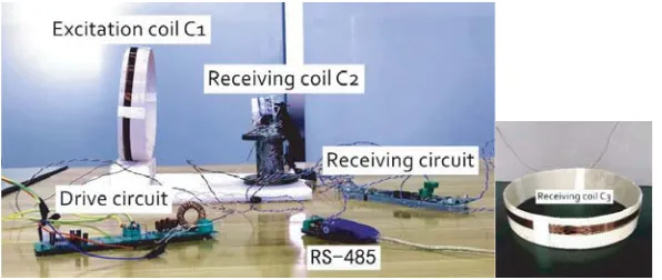
Experimental platform of the electromagnetic induction efficiency detection system is shown in Fig. 11. The platform includes the following parts: Transmitter coil C1, detection coil C2, drive circuit, receive circuit, RS485 communication, and receiver coil C3 used for efficiency detection. The system controller is TMS320F28335. The sine-wave excitation source in the signal-generate end is based on a class-E amplifier circuit. The signal generator combined with low pass filter and power amplifier circuit excites transmitter coil C1 to generate an alternating magnetic field.
Figure 11. Experimental platform.
4.2. Fluctuation Experiment
Recurrent fluctuations of distance within 0.2 m ∼0.3 m between transmitter coil and detection coil is executed to simulate the distance change caused by topography, bends, climbs, and other situations. 30 groups of amplitude data are detected by the system and recorded by python man-machine interface.
The Amplitude-Distance curve acquired by the detection system is shown in Fig. 12. It can be shown in Fig. 12 that while the excitation signal is constant, the amplitude and distance are under a negative correlation, which is consistent with the theoretical situation. The results show that the system has a good performance.
Figure 12. The amplitude — distance curve of system.
Figure 13. The coil efficiency-distance curve of system.
(a)
(b)
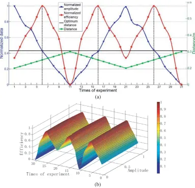
Figure 14. (a) The relation between the normalized data and the distance. (b) The three-dimensional curve between the normalized data and the distance.
It is inconvenient to analyze the data because of the different dimensions between amplitude and coil efficiency. Data normalization by min-max standardization is used in the paper. The normalized results are shown in Fig. 14, including the relations among the normalized amplitude, normalized coil efficiency and distance, and the forms of two-dimensional curve and three-dimensional curve.
Figure 14(a) shows that the amplitude and efficiency are not under a proportional relationship. The reason is that magnetically coupled resonant energy transfer mode has frequency classification characteristics. However, amplitude of the optimal efficiency distance is constant in the experiment. Therefore, detecting amplitude changes provides an approach to transmission efficiency adjustment on the line. Fig. 14(b) shows the three-dimensional curve of amplitude, efficiency, and distance, it provides a vivid way to see the disturbance to efficiency from distance.
5. CONCLUSION
In the paper, a single coil detection method is proposed based on electromagnetic induction. Detection structure fabrication, detection system design, and man-machine interface design are realized based on the method. The fluctuation experiment is proceeded, and the relationships among coil distance, detection coil amplitude, and coil efficiency are analyzed. The conclusions are as follows:
between amplitude and coil distance. In experiments of the paper, when an optimal transmission efficiency is 84% the amplitude is 63000 uV, and coil distance is 0.25 m.
(2) Dynamic radio power transmission in the rail transit field has a problem of efficiency fluctuation. In the paper, an electromagnetic detection solution is proposed, which has great significance for dynamic radio power transmission rail engineering.
Dynamic radio power transmission technology has a wide application in rail transit field. The influences of excitation signal, coil radius, coil relative position, and other factors are also a hotspot that needs to be studied.
REFERENCES
1. An, Y., et al., “Building an omnidirectional 3D color laser ranging system througha novel calibration method,”IEEE Transactions on Industrial Electronics, Vol. 66, 8821–8831, 2019.
2. Shi, G., W. Wang, and F. Zhang, “Precision improvement of frequency-modulated continuous-wavelaser ranging system with two auxiliary interferometers,” Optics Communications, Vol. 411, 152–157, 2018.
3. Andersone, I., “Probabilistic mapping with ultrasonic distance sensors,” Procedia Computer Science, Vol. 104, 362–368, 2017.
4. Tan, W. L., M. S. Vohra, and S. H. Yeo, “Depth and horizontal distance of surface roughness improvement on vertical surface of 3D-printed material using ultrasonic cavitation machining process with abrasive particles,”Key Engineering Materials, Vol. 748, 264–268, 2017.
5. Lai, Y., G.-Q. Liu, Z. Li, and Y. Lin, “Research on the method of seed water content measurement based on electromagnetic induction,”Progress In Electromagnetics Research M, Vol. 74, 191–200, 2018.
6. Liu, X.-F., B.-Z. Wang, and S.-Q. Xiao, “Electromagnetic subsurface detection using subspace signal processing and half-space dyadic Green’s function,” Progress In Electromagnetics Research, Vol. 98, 315–331, 2009.
7. Von Brzeski, J. G. and V. von Brzeski, “Topological intensity shifts of electro-magnetic field in lobachevskian spaces. Olbers paradox solved, deep space communication, and the new electromagnetic method of gravitational wave detection,” Progress In Electromagnetics Research, Vol. 43, 163–179, 2003.
8. Qu, X., Y. Li, G. Fang, and H. Yin, “A portable frequency domain electromagnetic system for shallow metal targets detection,”Progress In Electromagnetics Research M, Vol. 53, 167–175, 2017. 9. Huang, X., L. L. Tan, and Z. Chen, “Review and research progress on wireless power transfer
technology,” Transactions of China Electrotechnical Society, Vol. 28, 103–104, 2013.
10. Zhang, J. and Y. Cui, “Research on reliability of magnetic resonance coupling wireless charging device with series-parallel model,”Electrical & Energy Management, Vol. 5, 98–106, 2018.
11. Mai, R. and Y. Li, “Wireless power transfer technology and its research progress in rail transportation,”Journal of Southwest Jiaotong University, Vol. 51, 56–59, 2016.
12. Zhang, X., “Research on maximum transmission efficiency of resonance coupling wireless transmission in high-speed train system,” Transactions of China Electrotechnical Society, Vol. 30, 2015.
13. Zhang, H., et al., “Cooperative precoding for wireless energy transfer and secure cognitive radio coexistence systems,” IEEE Signal Processing Letters, Vol. 24, 540–544, 2017.
14. Jiang, C., K.-T. Chau, W. Han, and W. Liu, “Development of multilayer rectangular coils for multiple-receiver multiple-frequency wireless power transfer,” Progress In Electromagnetics Research, Vol. 163, 15–24, 2018.
15. Kim, J., W.-S. Choi, and J. Jeong, “Loop switching technique for wireless power transfer using magnetic resonance coupling,” Progress In Electromagnetics Research, Vol. 138, 197–209, 2013. 16. Kim, S., J. S. Ho, and A. S. Y. Poon, “Non-coil, optimal sources for wireless powering of
17. Li, Z., S. Cheng, and Y. Qin, “Novel rotor position detection method of line back EMF for BLDCM,”Electric Machines and Control, Vol. 14, 96–100, 2010.
18. Kim, C. W., F. P. S. Chin, and H. K. Garg, “Selection of frequency for Near Field Electromagnetic Ranging (NFER) based on its Cramer-Rao bound,”IEEE Signal Processing Letters, Vol. 14, 1000– 1003, 2007.
19. Wang, P., X.-T. Zhang, and L.-Y. Xu, “Indoor near field ranging algorithm based on adaptive time delay estimation,” Chinese Journal of Computers, Vol. 40, 1902–1917, 2017.
20. Evans, B. J. and L. M. Smith, “Cross-correlation-based method for determining the position and velocity of a railgun plasma armature from B-dot probe signals,” IEEE Transactions on Plasma Science, Vol. 19, 926–934, 2002.
21. Wang, B., C. Zhang, and B. Liu, “Study on the class E amplifier of wireless energy transmission based on magnetic coupling resonance,”Electronic Measurement Technology, Vol. 41, 41–44, 2018. 22. Xu, D. and F. Lin, “Design of CMOS class E power amplifier based on bootstrap cascode,”
Electronic Technology, Vol. 47, 78–81, 2018.