Ma r c h 2 0 1 7
Power Factor Improvement of Bridgeless Isolated
Cuk Converter-Fed Brushless DC Motor Drive
Using Fuzzy Controller
Mrs. C. BHARAT HI Assistant Professor
Department of Electrical & Electronics Engineering, GIIT S Engineering College, Aganampudi;
Visakhapatnam (Dt); A.P, India. Email:[email protected]
MS. P .LAVANYA Assistant Professor
Department of Electrical & Electronics Engineering, GIIT S Engineering College, Aganampudi;
Visakhapatnam (Dt); A.P, India. Email:[email protected]
Abstract-In this paper a Power Factor Correct ion Cuk converter fed Brushless DC Motor Drive using a Fuz z y Logic Controller is used. The Speed of t he Brushless dc mot or is controlled by varying the output of the DC capacitor. A Diode Bridge Rectifier followed by a Cuk converter is fed into a Brushless DC Motor to attain the maximum Power Factor. Here we are evaluating the three modes of operation in discontinuous mode and choosing the best method to achieve maximum Power Factor and to minimize the Total Harmonic Distortion.An approach of speed control of the BLDC mot or by controlling the dc link volt age of t he volt age source inverter (VSI) is used wit h a single volt age sen sor. T his facilitates the operation of VSI at fundament al frequency switching by using the electronic commutation of the BLDC mot or which offers reduced switching losses. Therefore, t he BLDC motor is electronically commutated such that t he VSI op erates in fundamental frequency swit ching for reduced switching losses. Moreover, the bridgeless configurat ion of t he CSC converter offers low conduction losses due to partial elimination of diode bridge rectifier at t he front end. T he p roposed configuration shows a considerable increase in efficiency as compared with the conventional scheme. T he mot or speed cont rol is imp lement ed using fuz z y logic cont roller. T he p rop osed met hod is simulat ed in M ATLAB/Simulink with PID and fuzzy logic controller for p recise sp eed cont rol.
Index Terms—Bridgeless isolated Cuk converter, brushless dc (BLDC) motor, discontinuous inductor current mode (DICM), p ower factor correction (PFC), power quality, voltage-source invert er (VSI).
I. INTRODUCTION
Brushless Dc Motor is recommended for many low cost applications such as household application, industrial, radio controlled cars, positioning and aeromodelling, Heating and ventilation etc. , because of its certain characteristics including high efficiency, high torque to weight ratio, more torque per watt , increased reliability, reduced noise, longer life, elimination of ionizing sparks from the commutator, and overall reduction of electromagnetic interference(EMI) etc. With no windings on the rotor, they are not subjected to any centrifugal forces, and because the windings are supported by the housing, they can be cooled by conduction, requiring no airflow inside the motor for cooling purposes. The motor’s internals can be entirely enclosed and protected from dust, dirt or any other foreign obstacles.
The two main factors that determine the power quality of a motor are the Power Factor (PF) and the total harmonic Distortion (THD) [1]. The Power Factor determines the amount of useful power being consumed by an electrical system. The term THD is defined as the ratio of the harmonic components of voltage (or current) to the voltage (or current) of the fundamental. So the Power Factor Correction (PFC) is the best method of improving the PF by making the [2-3] input to the power supply purely resistive or else due to the presence of non linear loads the input will contain phase displacement which causes harmonic distortion and thus the power factor gets degraded. The selection of mode of operation is a tradeoff between the allowed stresses on PFC switch and cost of the around system during the operating mode of front-end converter. The two different modes of operation are depending on design parameters; either continuous or discontinuous conduction mode approach may lead the converter. In this design, a BLDC motor drive fed by a PFC BL-Cuk converter operates in four modes [4]. At the time of starting or overloading inrush current is created. The inrush current occurring at start-up or overload was eliminated by operating the PFC in discontinuous conduction mode (DCM), it also gives natural protection for switches, low input ripple, and less electromagnetic interference (EMI) [5]. In this paper a fuzzy controlled BL- Cuk converter is analyzed in terms of harmonic reduction.
Ma r c h 2 0 1 7 is introduced to improve the rectifier power density
and/or to reduce noise emission via soft-switching techniques or coupled magnetic topologies. The Cuk converter has several advantages in power factor correction application [10] ns, such as easy implementation of transformer isolation, natural protection against inrush current occurring at start-up or overload current, lower input current ripple, and less electromagnetic interference(EMI) associated with discontinuous conduction mode topology.
A BLDC motor when fed by a diode bridge rectifier [11] (DBR) has higher conduction losses. The high conduction loss caused by the high forward voltage drop of the bridge diode begins to degrade the overall system efficiency. The heat generated within the bridge rectifier may destroy the individual diodes. Hence, it becomes necessary to utilize a bridge rectifier with higher current handling capability or heat dissipating characteristics. This increases the size and cost of the power supply, which is unacceptable for an efficient design. Bridgeless topologies seem to be the best solution for reducing the conduction and switching losses of the converter.
Fig.1 Conventional Cuk Rectifier
II. Op eration of PFC Based Bridgeles s Is o lated CUK Co n v erter
The operation of the proposed PFC converter is classified into two different sections for a line cycle and a switching cycle. Fig.2 shows six different modes of operation. Moreover, Fig.3 shows the associated waveforms of the PFC converter during a complete switching period.
A. Operation during Complete Line Cycle of Supply Voltage
The proposed bridgeless isolated Cuk converter is designed such that switches Sw1 and Sw2 conduct for
positive and negative half cycles of supply voltage, respectively.
Ma r c h 2 0 1 7
Fig.3. Different modes of operation of bridgeless isolated Cuk converter during (a)–(c) positive and (d)–(f) negative half cycle of
supply voltage.
During the positive half cycle of supply voltage, switch Sw1, inductors Li1 and Lo1, intermediate capacitors C11
and C21, and diodes D1 and Dp are in the state of
conduction and vice versa for the negative half cycle of supply voltage as shown in Fig.3(a)–(f). As shown in these figures, the proposed PFC converter operates in three different modes during the positive and negative half cycles of the supply voltage. Moreover, during the DICM operation, the current of output inductors (Lo1 and Lo2) become discontinuous in a switching period.
Fig.4. Waveforms of proposed converter in complete switching cycle. However, the current flowing in the input and magnetizing inductance of the high frequency transformer (HFT) (Li1, Li2, Lm1, and Lm2) and the voltage across the intermediate capacitor (C11, C12, C21, and C22) remain continuous in a complete switching period.
III. Op eratio n d u rin g Co mp lete Switch in g Cy cle Fig.3(a)–(c) shows three modes of operation of a bridgeless isolated Cuk converter in a switching period for the positive half cycle of the supply voltage. Fig.3 shows its associated waveforms in DICM (Lo) mode of operation as follows.
Mode P-I: In this mode, when the switch (Sw1) is turned on, the input inductor (Li1), output inductor (Lo1), and magnetizing inductance of HFT (Lm1) start charging as shown in Fig.3(a). The input side
intermediate capacitor (C11) supplies the energy to the HFT, and the output side intermediate capacitor (C21) supplies the required energy to the dc link capacitor as shown in Fig.3.
Mode P-II: When the switch (Sw1) is turned off, the input inductor (Li1), output inductor (Lo1), and magnetizing inductance of HFT(Lm1) start discharging as shown in Fig .3(b). The intermediate capacitors (C11 and C21) charge, and the dc link capacitor (Cd) discharges in this interval as shown in Fig.4.
Mode P-III: During this interval, the output side inductor (Lo1) is completely discharged, and the input inductor (Li1) and magnetizing inductance of HFT (Lm1) continue to discharge as shown in Fig. 3(c). The output side intermediate capacitor (C21) continues to charge, and the dc link capacitor (Cd) supplies the required energy to the BLDC motor (BLDCM) as shown in Fig.4.
In a similar way, the operation for the negative half cycle of the supply voltage is realized. Initially, the intermediate capacitors (C11, C12, C21, and C22) are completely discharged and are charged during the operation of the PFC converter. The voltage across the input side intermediate capacitors (C11 and C12) depends upon the instantaneous input voltage; hence, the initial charging of C11 and C12 is zero. However, the output side intermediate capacitors (C21 and C22) are not completely discharged in a switching period or a half line cycle of the supply voltage due to the voltage maintained at the dc link capacitor (Cd).
Moreover, during the operation of the PFC converter in the positive half cycle, the energy storage components on the primary side of the HFT (i.e., Li2, C12 and Lm2) remain in non-conducting state and are completely discharged. However, the energy storage components on the secondary side of HFT (i.e., C22) remain charged at its full voltage due to the unavailability of a discharging path and the presence of the dc link capacitor (Cd).
IV. DESIGN OF BRIDGELESS ISOLA TED CUK CONVERTER
A bridgeless isolated Cuk converter is designed to operate in DICM such that the current flowing in the output inductors (Lo1and Lo2) becomes discontinuous in a switching period. A PFC converter of 250 W (Pmax)
is designed for the selected BLDC motor (specifications given in the Appendix). For a wide range of speed, the dc link voltage is controlled from 50 V (Vdcmin) to a
rated voltage of 130 V (Vdcmax) with a supply voltage
variation from 170 V (Vsmin) to 270 V (Vsmax).
The input voltage vs applied to the PFC converter is given as
(1) Where Vm is the peak input voltage (i.e., √2VS) and fL
Ma r c h 2 0 1 7 Now, the instantaneous value of the rectified voltage is
given as
(2) Where | | represents the modulus function.
The output voltage Vdc of a bridgeless isolated Cuk converter which is a buck–boost configuration is given as
(3) Where D represents the duty ratio and(N2/N1) is the turn’s ratio of the HFT which is taken as 1/2 for this application. The instantaneous value of the duty ratio, D (t), depends on the input voltage and dc link voltage. Instantaneous duty ratioD (t) is obtained by substituting (2) in (3) as follows:
(4) Since the speed of the BLDC motor is controlled by varying the dc link voltage of VSI, therefore, the instantaneous power Pi is taken as a linear function of Vdc as follows:
(5) Where Vdcmax represents the maximum dc link voltage
and Pmax is the rated power of the PFC converter. Using
(5), the minimum power at the minimum dc link voltage of 50 V (Vdcmin) is calculated as 96 W (Pmin).The value
of the input inductor to operate in continuous conduction is decided by the amount of permitted ripple current (η) and is given as [12]
(6) Where fs is the switching frequency which is taken as 20 kHz. The maximum inductor ripple current is obtained at the rated condition, i.e., Vdcmax (Pi = Pmax)
for a minimum value of the supply voltage (Vsmin).
Hence, the input side inductor is designed at the peak value of the minimum supply voltage (√2Vsmin). Using (6), the value of the input side inductors (Li1 and Li2) is calculated as 5.005 mH for a permitted current ripple of 50% (η) of the input current. Hence, the input side inductor of 5 mH is selected for its operation in continuous conduction. The critical value of the output side inductor (Loc) to operate at the boundary of CICM
and DICM is given as [12]
(7)
The maximum current ripple in an inductor occurs at the maximum power and at the minimum value of the supply voltage (i.e., Vsmin). Hence, the output inductor is calculated at the peak of the supply voltage (i.e., Vin = √2Vsmin).
The critical value of output side inductors is calculated at the minimum (Loc50) and maximum (Loc130) values of dc link voltages using (7) as 459.79 and 811.93 μH, respectively. Hence, the critical value of the output inductor is selected lower than the minimum value, i.e., Loc50, to ensure a discontinuous conduction even at lower values of dc link voltages. Therefore, the output inductor (Lo1 and Lo2) of 70 μH is selected for its operation in discontinuous conduction. The value of the magnetizing inductance of HFT to operate in CICM is decided by the permitted ripple current (ξ) as [11]
(8) The maximum current occurs at the maximum dc link voltage (i.e., Pmax) and the minimum supply voltage (i.e., Vsmin).Therefore, the value of the magnetizing inductance (Lm1 and Lm2) for a permitted ripple current (ξ) of 50% is calculated using (8) as 6.006 mH and is selected as 6 mH. The value of input side intermediate capacitors to operate in CCM with a permitted ripple voltage of κ% of VC1 is given as [11]
(9) The input side intermediate capacitors (C11 and C12) are calculated at the maximum value of voltage ripple corresponding to the maximum supply voltage (Vsmax)
and at rated dc link voltage. Now, for a permitted ripple voltage of 25%, the values of C11 and C12 are calculated using (9) as 204 nF and are selected as 220 nF.
The value of output side intermediate capacitors to operate in CCM with a permitted ripple voltage of χ% of VC2 is given as [11]
(10) Now, the maximum ripple voltage occurs at rated condition and at the maximum value of dc link voltage (Vdcmax). Hence, the output side intermediate capacitor
(Cd) is calculated at the maximum permitted ripple voltage of 10% (χ) of VC21,22 at the maximum (C2c270) and minimum (C2c170) values of supply voltage as 2.99 and 3.84 μF, respectively. Therefore, the output side intermediate capacitors (C21 and C22) are selected higher than C2c85 of the order of 4.4 μF. The value of the dc link capacitor (Cd) is calculated as [11]
Ma r c h 2 0 1 7 Where ΔVdc represents the permitted ripple in the dc
link voltage.
The worst case design occurs for the minimum value of dc link voltage, i.e., 50 V. Hence, for a permitted ripple voltage of 3% (ρ), the value of the dc link capacitor is calculated using (11) as 2038 μF, and it is selected as 2200 μF.
A low-pass LC filter is used to avoid the reflection of higher order harmonics in the supply system. The maximum value of the filter capacitance (Cmax) is given
as [40]
(12) Where θ is the displacement angle between the fundamental value of the supply voltage and supply current and is taken as 2◦.
The maximum value of the filter capacitor is calculated using (12) as 574.4 nF and is selected as 330 nF.The value of the filter inductor is designed by considering the source impedance (Ls) of 4%–5% of the base impedance. Hence, the additional value of inductance required is given as
(13) Where fc is the cutoff frequency which is selected such that fL< fc< fS. Therefore, fc is taken as fS/10.Hence; the
value of the filter inductance is calculated using (13) as 3.77 mH.
V. Co n trol of PFC Bridgeless Isolated CUK Converter-Fed BLDC M o to r Driv e
The control of the proposed BLDC motor drive is divided into two categories of control of the PFC converter for dc link voltage control and control of three-phase VSI for achieving the electronic commutation of the BLDC motor as follows.
A . Control of Front -End PFC Converter
A voltage follower approach is used for the control of the PFC-based bridgeless isolated Cuk converter operating in DICM. This control scheme consists of a reference voltage generator, a voltage error generator, a voltage controller, and a PWM generator. A “Reference Voltage Generator” generates a reference voltage V*dc by multiplying the reference speed (ω∗) with the motor’s voltage constant (kv) as
(14) The “Voltage Error Generator” compares this reference dc link voltage (V*dc ) with the sensed dc link voltage (Vdc) to generate an error voltage (Ve) given as
(15) Where “k” represents the kth sampling instance. This error voltage Ve is given to a voltage proportional
integral (PI) controller to generate a controlled output voltage (Vcc) which is expressed as
(16) Finally, the PWM signals for switches Sw1 and Sw2 are generated by comparing the output of the PI controller (Vcc) with the high-frequency saw tooth signal (md) given as
(17) Where PWMSw1 and PWMSw2 represent the gate signals to PFC converter switches Sw1 and Sw2,
respectively.
In this control algorithm, (17) shows the solid-state switches of the PFC converter operating at half cycles of supply voltages. However, to avoid the sensing of supply voltage for zero crossing detection, only one PWM signal is generated to drive both solid-state switches of the PFC converter, i.e., PWMSw1 =PWMSw2. Moreover, the PFC converter is operating in DCM; therefore, the input current shaping in phase with the supply voltage is obtained inherently, and a unity PF is achieved at the ac mains.
B. Control of BLDC Motor Electronic Commutation An electronic commutation of the BLDC motor includes the proper switching of the VSI in such a way that a symmetrical dc current is drawn from the dc link capacitor for 120◦ and is placed symmetrically at the center of the back electro-motive force (EMF) of each phase. A Hall-effect position sensor is used to sense the rotor position on a span of 60◦; which is required for the electronic commutation of the BLDC motor. As shown in Fig. 4, when two switches of the VSI, i.e., S1 and S4, are in conducting states, a line current iab is drawn from the dc link capacitor whose magnitude depends on the applied dc link voltage (Vdc),
back EMFs (ean and ebn), resistances (Ra and Rb), and
self-inductance and mutual inductance (La, Lb, and M) of stator windings. This current produces an electromagnetic torque (Te) which, in turn, increases the speed of the BLDC motor.
VI. INTRODUCTION TOFUZZYLOGIC
CONTROLLER
Ma r c h 2 0 1 7 performance of proposed controllers. Furthermore,
design of fuzzy logic controller can provide desirable both small signal and large signal dynamic performance at same time, which is not possible with linear control technique. Thus, fuzzy logic controller has been potential ability to improve the robustness of dc-to-dc converters. The basic scheme of a fuzzy logic controller is shown in Fig 6 and consists of four principal components such as: a fuzzification interface, which converts input data into suitable linguistic values; a knowledge base, which consists of a data base with the necessary linguistic definitions and the control rule set; a decision-making logic which, simulating a human decision process, infer the fuzzy control action from the knowledge of the control rules and linguistic variable definitions; a de-fuzzification interface which yields non fuzzy control action from an inferred fuzzy control action [10].
Fig.5. General Structure of the fuzzy logic controller on closed-loop system
The fuzzy control systems are based on expert knowledge that converts the human linguistic concepts into an automatic control strategy without any complicated mathematical model [10]. Simulation is performed in buck converter to verify the proposed fuzzy logic controllers.
Fig.6. Block diagram of the Fuzzy Logic Controller (FLC) for dc-dc converters
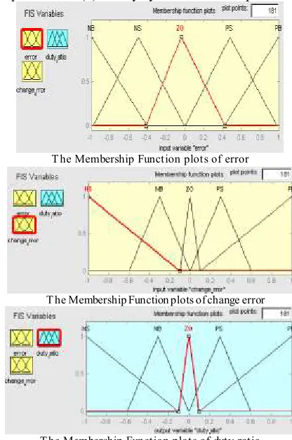
A. Fuzzy Logic Membership Functions:
The dc-dc converter is a nonlinear function of the duty cycle because of the small signal model and its control method was applied to the control of boost converters. Fuzzy controllers do not require an exact mathematical model. Instead, they are designed based on general knowledge of the plant. Fuzzy controllers are designed
to adapt to varying operating points. Fuzzy Logic Controller is designed to control the output of boost dc-dc converter using Mamdani style fuzzy inference system. Two input variables, error (e) and change of error (de) are used in this fuzzy logic system. The single output variable (u) is duty cycle of PWM output.
T he Membership Function plots of error
T he Membership Function plots of change error
T he Membership Function plots of duty ratio
B. Fuzzy Logic Rules:
The objective of this dissertation is to control the output voltage of the boost converter. The error and change of error of the output voltage will be the inputs of fuzzy logic controller. These 2 inputs are divided into five groups; NB: Negative Big, NS: Negative Small, ZO: Zero Area, PS: Positive small and PB: Positive Big and its parameter [10]. These fuzzy control rules for error and change of error can be referred in the table that is shown in Table I as per below:
Table I
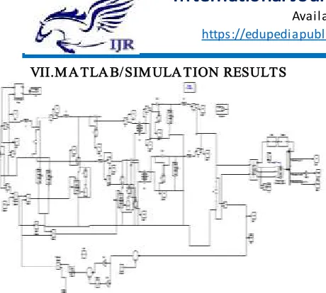
Ma r c h 2 0 1 7 VII.M A TLA B/SIM ULA TION RESULTS
Fig 7 Matlab/simulation circuit of proposed configuration of a bridgeless isolated Cuk converter-fed BLDC motor drive.
Fig 8 simulation wave form of T est results of the proposed drive during its operation at rated loading condition with dc link voltage as
130 V
Fig 9 simulation wave form of T est results of the proposed drive during its operation at rated loading condition with dc link voltage as
50 v
Fig 10 simulation wave form of source voltage
Fig 11 T est results of the proposed drive during its operation at rated condition showing (a) input inductor currents, (b) output
inductor currents, and (c) HFT currents
Fig 12 T est results of the proposed drive during its operation at rated condition showing intermediate capacitor voltages (a) VC11 and
VC12 and (b) VC21 and VC22.
Fig 13 T est results of the proposed drive during its operation at rated condition showing (a) voltage and current stress on PFC converter
switches and (b) its enlarged waveforms.
(a)
Ma r c h 2 0 1 7
(c)
Fig 14 T est results of the proposed drive during (a) starting at dc link voltage of 50 V, (b) speed control corresponding to change in dc link voltage from 50 to 100 V, and (c) supply voltage fluctuation from 250
to 200 V.
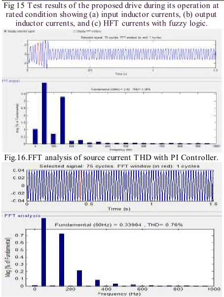
Fig 15 T est results of the proposed drive during its operation at rated condition showing (a) input inductor currents, (b) output
inductor currents, and (c) HFT currents with fuzzy logic.
Fig.16.FFT analysis of source current T HD with PI Controller.
Fig.17. FFT analysis of source current T HD with fuzzy logic
VIII. CONCLUSION
The bridgeless Cuk converter fed BLDC motor drive improves the power factor at the AC mains near to the unity with precise speed control of fuzzy logic controller with low THD. The suitable controller for PFC operation of BLDC motor drives has been analyzed. FLC seems to be the best controller in
performance improvement of BLDC motor drives for attaining the power factor near to unity.The Simulink model for a BLDC Motor drive system with stator current control by using Simulink blocks has been developed and operated at rated speed. A mathematical expression of the system is simply incorporated in the MATLAB simulation and the usage of numerous appliance boxes and support guides simplifies the simulation of large control system. Simulink is effective of recommending real time results with reduced simulation time process and debugging. Usually in such drive system the inverter is driven by Fuzzy Logic controller. The proposed drive system has maintained high power factor and improved power quality for a wide range of speed control for varying supply voltages. The Simulink simulation allows performance study of BLDC Motor drives with DCM. It is found that the power factor is near unity with the use of BL-Cuk converter. The efficiency increases due to the increase in the power factor.
RE FE RE NCE S
[1] C. L. Xia, Permanent Magnet Brushless DC Motor Drives and Controls. Hoboken, NJ, USA: Wiley, 2012.
[2] C. L. Xia, Brushless DC Motor Drives and Controls .Beijing, China: Wiley, 2012.
[3] B. Singh and V. Bist, “An improved power quality bridgeless Cuk converter fed BLDC motor drive for air conditioning system,” IET Power Electron., vol. 6, no. 5, pp. 902– 913, 2013.
[4] Pradeep Kumar, P.R.Sharma and Ashok Kumar, “Simulation and design of power factor correction prototype for BLDC motor control,” European scientific journal, vol. 9, no. 12, April 2013.
[5] A. Sabzali, E. H. Ismail, M. Al-Saffar, and A. Fardoun, “New bridgeless DCM sepic and Cuk PFC rectifiers with low conduction and switching losses,” IEEE T rans. Ind. Appl., vol. 47, no. 2, pp. 873–881,Mar./Apr.2011.
[6] G. Moschopoulos and P. Kain, “A novel single-phase soft-switched rectifier with unity power factor and minimal component count,” IEEE Trans. Ind. Electron., vol. 51, no. 3, pp. 566–575, Jun. 2004.
[7] W. Choi, J.Kwon, E. Kim, J. Lee, and B.Kwon, “Bridgeless boost rectifier with low conduction losses and reduced diode reverse-recovery problems,” IEEE Trans. Ind. Electron., vol. 54, no. 2, pp. 769–780, Apr.2007.
[8] E. H. Ismail, “Bridgeless SEPIC rectifier with unity power factor and reduced conduction losses,” IEEE Trans. Ind. Electron., vol. 56, no. 4, pp.1147–1157, Apr. 2009.
[9] Y.-S. Roh, Y.-J. Moon, J.-C. Gong, and C. Yoo, “Active power factor correction (PFC) circuit with resistor-free zero-current detection,” IEEE Trans. Power Electron., vol. 26, no. 2, pp. 630–637, Feb. 2011.
[10] Singh, B., and Bist, V., “Power quality improvement in PFC bridgeless Cuk fed BLDC motor drive”, Int. J. Emerg. Elect. Power Syst., Vol. 14,No. 3, PP. 285–296, 2013.
[11] Bist, V., and Singh, B., “A reduced sensor PFC BL zeta converter based VSI fed BLDC motor drive”, Elect. Power Syst. Res., Vol. 98, PP. 11– 18, May 2013.
Ma r c h 2 0 1 7
Aganampudi, Visakhapatnam (Dt), Andhra Pradesh, India. Her area of Interest is Electric Drives , Power Electronics, Power Systems.
Professor in Department of EEE , GIITS Engineering College, Aganampudi, Visakhapatnam (Dt), Andhra Pradesh, India. Her area of Interest is Electric Drives.
C.BHARATHI Received her
B.Tech Degree from
Ranippettai Engineering
College, Walaja, Vellore, Tamilnadu and M.Tech from Bharathi University, Chennai. She is currently working as
Assistant Professor in
Department of EEE, GIITS Engineering college,
P.LAVANYA Received her
B.Tech Degree from
Sanketika Vidya Paishad, P.M.Palem, Visakhapatnam, Andhrapradesh and M.Tech from DADI Institute of Engineering & Technology, Anakapalle, Visakhapatnam,
Andhrapradesh. She is