Scholarship@Western
Scholarship@Western
Electronic Thesis and Dissertation Repository
1-22-2013 12:00 AM
Engineering nanocomposites for antimicrobial application
Engineering nanocomposites for antimicrobial application
Binyu Yu
The University of Western Ontario
Supervisor Jun Yang
The University of Western Ontario
Graduate Program in Biomedical Engineering
A thesis submitted in partial fulfillment of the requirements for the degree in Doctor of Philosophy
© Binyu Yu 2013
Follow this and additional works at: https://ir.lib.uwo.ca/etd
Part of the Biomaterials Commons, and the Other Biomedical Engineering and Bioengineering Commons
Recommended Citation Recommended Citation
Yu, Binyu, "Engineering nanocomposites for antimicrobial application" (2013). Electronic Thesis and Dissertation Repository. 1083.
https://ir.lib.uwo.ca/etd/1083
This Dissertation/Thesis is brought to you for free and open access by Scholarship@Western. It has been accepted for inclusion in Electronic Thesis and Dissertation Repository by an authorized administrator of
(Spine title: Engineering nanocomposites for anti-biofouling application)
(Thesis format: Integrated Article)
by
Binyu Yu
Biomedical Engineering Graduate Program
Faculty of Engineering
A thesis submitted in partial fulfillment of the requirements for the degree of
Doctor of Philosophy
The School of Graduate and Postdoctoral Studies The University of Western Ontario
London, Ontario, Canada
ii
THE UNIVERSITY OF WESTERN ONTARIO School of Graduate and Postdoctoral Studies
CERTIFICATE OF EXAMINATION
Supervisor
______________________________ Dr. Jun Yang
Supervisory Committee
______________________________ Dr. Leo Lau
______________________________ Dr. Jin Zhang
Examiners
______________________________ Dr. Jesse Zhu
______________________________ Dr. Paul Charpentier
______________________________ Dr. Xueliang A Sun
______________________________ Dr. Jesse Greener
The thesis by
Binyu Yu
entitled:
Engineering nanocomposite for antimicrobial application
is accepted in partial fulfillment of the requirements for the degree of
Doctor of Philosophy
______________________ _______________________________
iii
Abstract
In this thesis, active and passive antimicrobial methods have been applied to fabricate antifouling surfaces. In the first study, we reported the synthesis and characterization of neat
TiO2 and Ag-TiO2 composite nanofilms prepared on silicon wafer by sol-gel method. The
synthesized Ag-TiO2 thin films showed enhanced bactericidal activities compared to the neat
TiO2 nanofilm both in the dark and under UV illumination. The advantage of Ag-TiO2
nano-composites is to expand the nanomaterial’s antibacterial function to a broader range of working conditions. In the second study, we reported the synthesis, characterization and
environmental application of nitrogen doped TiO2 photocatalyst in the form of powder and
film. TiO2 photocatalysts were synthesized by hydrolysis of titanium tetra-isopropoxide in
the presence of urea as nitrogen source. The visible light induced photocatalytic inactivation of bacteria (Escherichia coli) with the obtained nano-powders and nano-films was tested.
In the following study, we reported the successful formation of a titanium dioxide (TiO2)
layer on butyl rubber (BR) substrate, cotton sheet and silicon wafer surfaces by using modified liquid phase deposition (LPD) method at mild environmental conditions. Various synthetic conditions were studied to control the morphology and nanostructures of the
deposited TiO2 coatings. Superoleophobic TiO2 coatings were prepared after surface
fluorination. The formed TiO2 coatings showed excellent antibacterial adhesion ability.
non-iv
specific protein adsorption and show antibacterial adhesion. It is a promising material for biomedical and industrial applications.
v
Co-Authorship Statement
This doctoral thesis has been carefully prepared according to the regulations for an integrated-article format thesis stipulated by the Faculty of Graduate and Postdoctoral Studies at the University of Western Ontario, and has been co-authored as follows:
CHAPTER 2: SYNTHESIS OF SILVER-TIO
2COMPOSITE
NANO-THIN FILM FOR ANTIMICROBIAL APPLICATION
All the preparation for experimental testing and set-up was undertaken by B. Yu under the supervision of Dr. J. Yang. All the experiments were conducted by B. Yu under the supervision of Dr. J. Yang. Drafts of Chapter 2 were prepared by B. Yu and reviewed by Dr. J. Yang. A paper co-authored by B. Yu, W.M.Lau and J. Yang has been published on
Nanotechnology
.
CHAPTER 3: PREPARATION AND CHARACTERIZATION OF
NITROGEN-TIO
2PHOTOCATALYST
WITH
HIGH
CRYSTALLINITY AND ENHANCED PHOTOINACTIVATION
All the preparation for experimental testing and set-up was undertaken by B. Yu under the supervision of Dr. J. Yang. All the experiments were conducted by B. Yu under the supervision of Dr. J. Yang. Drafts of Chapter 3 were prepared by B. Yu and reviewed by Dr.
J. Yang. A paper co-authored by B. Yu, and J. Yang is to be submitted.
CHAPTER 4: CHARACTERIZATION AND ANTIBACTERIAL
ADHESION PERFORMANCE OF TIO
2COATING PREPARED
BY LIQUID PHASE DEPOSITION METHOD
vi
supervision of Dr. J. Yang. Drafts of Chapter 4 were prepared by B. Yu and reviewed by Dr.
J. Yang. A paper co-authored by B. Yu, and J. Yang is to be submitted
.
CHAPTER 5: A NOVEL METHOD FOR ENGINEERING
SUPEROLEOPHOBIC
AND
CONDUCTIVE
DUAL-FUNCTIONAL
COATINGS
ON
FLEXIBLE
AND
STRETCHABLE SUBSTRATES
All the experiments were conducted by B. Yu under the supervision of Dr. J. Yang. An invention report was submitted to World Discoveries. Drafts of Chapter 5 were prepared by B. Yu and reviewed by Dr. J. Yang. A paper co-authored by B. Yu, and J. Yang is to be
submitted.
CHAPTER 6: SUPEROLEOPHOBIC SURFACES AND THE
RESISTANCE TO PROTEIN ADSORPTION AND BACTERIAL
ADHESION
All the preparation for experimental testing and set-up was undertaken by B. Yu under the supervision of Dr. J. Yang. All the experiments were conducted by B. Yu under the supervision of Dr. J. Yang. Drafts of Chapter 6 were prepared by B. Yu and reviewed by Dr.
vii
ACKNOWLEDGMENTS
First I would like to thank my research supervisor, Prof. Jun Yang, for his guidance, support and discussions throughout my PhD research work. I also thank Prof. Jun Yang for providing me the opportunity to work with industry partners, including Ross-tech Inc. and LANXESS. I would also like to thank my committee members, Prof. Leo Lau and Prof. Jin Zhang, for your time and constructive suggestion for this thesis.
Furthermore, I would like to thank all my colleagues, to these who help me and challenge me during my PhD study. My sincere thanks also go to Dr. Richard Gardiner, Karen Nygard and Nicole Bechard from Biotron, Kimberley R. Law from Department of Earth Science for your discussions and helpful technical support during this research work. I also acknowledge technicians and scientists in Surface Science Western, including Mr. Ross Davidson, Ms. Mary Jane Walzak, Mr. Brad Kobe, Dr. Mark Biesinger, Dr. Heng-Yong Nie and Ms. Heather Bloomfield, for the help and assistance in sample measurement. My thanks also go to my other friends in and outside of Western for the generous help and encouragement during my PhD study.
viii
Table of Contents
CERTIFICATE OF EXAMINATION ... ii
Abstract ... iii
Co-Authorship Statement ... v
ACKNOWLEDGMENTS ... vii
Table of Contents ... viii
List of Tables ... xiii
List of Figures ... xiv
Chapter 1 ... 1
1 General introduction ... 1
1.1 Problems of biofouling in the environment and biomedical field ... 1
1.2 Principle of Biofouling ... 3
1.2.1 Protein adsorption ... 3
1.2.2 Bacterial adhesion ... 6
1.3 Strategies to prepare antifouling surface ... 10
1.3.1 Active antifouling coatings ... 10
1.3.2 Passive antifouling coatings ... 16
1.4 Scope of the thesis ... 25
1.5 Literature citations ... 27
Chapter 2 ... 41
2 Synthesis of Ag-TiO2 composite nano-thin film for antimicrobial application .... 41
2.1 Introduction ... 41
2.2 Materials and methods ... 43
2.2.1 Materials ... 43
ix
2.2.3 Materials characterization ... 45
2.2.4 Measurements of photoinduced super-hydrophilicity ... 45
2.2.5 Antibacterial activity evaluation ... 46
2.3 Results and discussion ... 47
2.3.1 Characterization of the TiO2 and Ag-TiO2 films ... 47
2.3.2 Hydrophilicity ... 55
2.3.3 Antibacterial activity evaluation ... 56
2.4 Conclusions ... 60
2.5 References ... 61
Chapter 3 ... 65
3 Preparation and characterization of Nitrogen doped TiO2 photocatalst with high crystallinity and enhanced photoinactivation... 65
3.1 Introduction ... 65
3.2 Materials and methods ... 67
3.2.1 Chemicals and materials ... 67
3.2.2 Preparation of materials ... 67
3.2.3 Characterization methods ... 68
3.2.4 Photocatalytic activity measurement ... 69
3.3 Results and discussion ... 70
3.3.1 Characterization of N-TiO2 ... 70
3.3.2 Photocatalytic degradation of Methyl blue under visible light ... 77
3.3.3 Antibacterial activity evaluation ... 80
3.4 Conclusions ... 82
3.5 References ... 83
Chapter 4 ... 88
x
4.1 Introduction ... 88
4.2. Methodology ... 89
4.2.1 Chemicals and materials ... 89
4.2.2 Preparation of seeds ... 90
4.2.3 Preparation of TiO2 coating ... 90
4.2.4 Surface characterization ... 91
4.2.5 Tape test ... 91
4.2.6 Bacterial adhesion test ... 91
4.3 Results and Discussion ... 92
4.3.1 Reaction mechanism of LPD-derived TiO2 coating ... 92
4.3.2 Characterization of LPD-derived TiO2 coating on different substrates ... 93
4.3.3 Morphology control by addition of seeds ... 98
4.3.4 Effect of the amount of additives ... 99
4.3.5 Effect of the surface property of additives ... 101
4.3.6 Customized the LPD-derived TiO2 coating in the presence of seed ... 102
4.3.7 Surface wettability ... 104
4.3.8 Bacterial adhesion activity of the LPD-derived TiO2 coating ... 106
4.4 Conclusions ... 107
4.5 References ... 108
Chapter 5 ... 112
5 A novel method for engineering superoleophobic and conductive dual-functional coatings on flexible and stretchable substrates ... 112
5.1 Introduction ... 112
5.2 Experimental Section ... 114
xi
5.2.2 Preparation of Ultraviolet (UV) cross-linked coatings on butyl rubber
surface ... 115
5.2.3 Wettability Test ... 116
5.2.4 Tensile Testing ... 116
5.2.5 Surface Characterization ... 116
5.2.6 Conductivity Measurements ... 117
5.3 Results and Discussion ... 117
5.3.1 Superoleophobic results for UV cross-linked coatings ... 117
5.3.2 Adhesion of the UV Cross-linked Coatings ... 124
5.3.3 Effect of cross-linking method on contact angle ... 126
5.3.4 Effect of Strain on Contact Angle ... 127
5.3.5 Electrical Conductivity of the UV cured coatings... 128
5.4 Conclusions ... 129
5.5 References ... 130
Chapter 6 ... 132
6 Superoleophobic surfaces and the resistance to protein adsorption and bacterial adhesion ... 132
6.1 Introduction ... 132
6.2 Materials and methods ... 134
6.2.1 Materials ... 134
6.2.2 General procedure for silane-coated glass/silicon wafer surface ... 135
6.2.3 Preparation of PIP-CB-TiO2 coatings on PET ... 135
6.3 Surface contact angle measurement and surface characterization ... 136
6.3.1 Contact angle measurements ... 136
6.3.2 XPS, SEM and EDX measurements ... 136
6.3.3 Atomic force microscope (AFM) characterization ... 136
xii
6.5 Antifouling experiment ... 138
6.5.1 Static growth ... 138
6.5.2 Dynamic growth ... 138
6.6 Results and Discussion ... 139
6.6.1 X-ray photoelectron spectroscopy ... 139
6.6.2 Surface morphology of various coatings ... 144
6.6.3 Single protein adsorption on various surfaces ... 153
6.6.4 Bacterial adhesion on various surfaces ... 158
6.7 Conclusions ... 162
6.8 References ... 162
Chapter 7 ... 166
xiii
List of Tables
Table 2-1: Composition of Ag-TiO2 composite films according to EDX analysis ... 53
Table 2-2: Surface roughness of the resultant films with different silver content. ... 55
Table 2-3: The antibacterial test result of the composite films with different silver content against E. coli. ... 57
Table 5-1: Concentration of solutions/dispersions for UV cured spray coatings. ... 118
Table 5-2: Apparent contact angle of UV cross-linked spray coatings. ... 122
Table 6-1: XPS elemental analysis. Atomic percent concentration (at.%) of the elements taken on fluorinated polymer-nanoparticle composite surface and reference PEO and PFTS modified silicon wafer surface. ... 140
xiv
List of Figures
Figure 1-1: Schematic view of simplification of protein model, with hydrophobic, neutral hydrophilic, negatively and positively charged domains (sides). The adsorption occurred on the domains that can interact with a surface having comparable properties. Reproduced from Reference [14]. ... 4
Figure 1-2: Scheme of biofilm development. Reproduced from Reference [43]. ... 7
Figure 1-3: Scheme of the biofilm development. Details of the step 2 in the bacterial adhesion process. Reproduced from Reference[43]. ... 8
Figure 1-4: Schematic photoexcitation on TiO2 after UV excitation. Reproduced from
Reference [96]. ... 12
Figure 1-5: The photodegradation of bacteria. Reproduced from Reference [105]. ... 14
Figure 1-6: The chemical structures of polymers for antifouling coating. ... 19
Figure 1-7: Three different wetting models. (1) Young’s model, (2 ) Wenzel model and (3) Cassie-Baxter model. ... 23
Figure 2-1: Wide-angle x-ray scattering patterns of the result films with different Ag contents: sample SG0-SG4 is labeled as (a)-(e) in sequence. ... 47
Figure 2-2: XPS spectra of TiO2 (a) and Ag-TiO2 (b) composite films of SG4. ... 48
Figure 2-3: High-resolution XPS spectra of Ag 3d5/2 in Ag-TiO2 composite film SG4. (a)
before UV exposure and (b) after 0.6 mW cm-2 UV exposure for 1 h. ... 49
Figure 2-4: Scanning electron micrographs of the (a) the neat TiO2 film surface of SG0, (b)
SG1, (c) SG2, (d) SG3 and (e) SG4 Ag-TiO2 composite film surfaces. (a)-2, (b)-2, (c)-2,
xv
Figure 2-5: AFM top view images (left) and AFM angle view images(right) of the composite films: (a) SG0, (b) SG2, (c) SG3, (d) SG4... 54
Figure 2-6: Zone of inhibition test results. Comparison of the composite Ag-TiO2 film and
the neat TiO2 film for E.coli with agar plating. ... 57
Figure 2-7: Killing ratio of E.coli in the liquid film on Ag-TiO2 compostie film and neat TiO2
film under 1h UV light illumination (0.6mW cm-2) and in the dark for 1h. For the blank
silicon wafer, the killing ratio is 18±5% under the same UV-irradiation. ... 58
Figure 3-1: XRD patterns of the doped and undoped TiO2 nanoparticles prepared at different
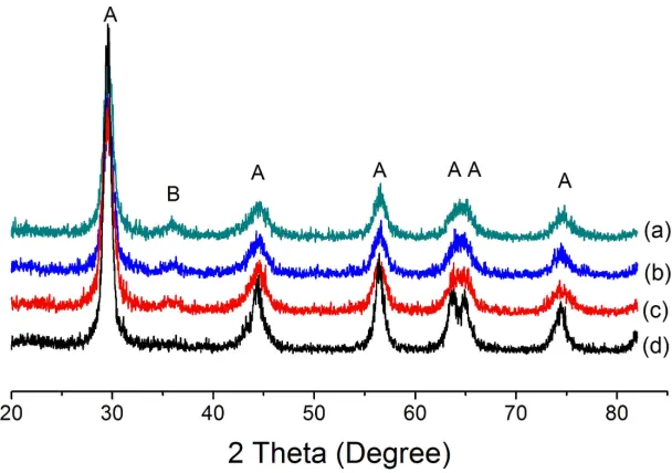
pH with r = 100, (a) pH = 1, without urea, (b) pH = 1, with urea, (c) pH = 3, without urea, (d) pH = 3, with urea. A represents anatase phase and B reprensents brookite phase. All the powder samples have been annealed at 400 oC for 4 h. ... 71
Figure 3-2: XRD patterns of TiO2 powder samples prepared with molar ratio of water to
TTIP at 10 and pH = 3 in the presence of various content of urea, (a) NT4, (b) NT3, (c) NT2, (d) NT1 and (e) NT0. ... 72
Figure 3-3: TEM image of typical TiO2 powder (sample NT3). ... 73
Figure 3-4: (a) The XPS spectra of N-TiO2 (NT3). (b) Ti 2p of N-TiO2 XPS region; (c) N 1s
of N-TiO2 XPS region. ... 74
Figure 3-5: N2 adsorption-desorption isotherm of (a) homemade pure TiO2, (b) N-doped TiO2
(NT3) and (c) P25. ... 75
Figure 3-6: UV-visible diffuse reflectance spectra of the N-TiO2 with various content of urea
in the precursor solution as well as the undoped TiO2 samples. (a) NT1, (b) NT2, (c) NT3
and (d) NT4. The insets on the right side show the pictures of (i) undoped and (ii) N-TiO2
sample (NT3). ... 76
Figure 3-7: Comparison of percentage degradation of methylene blue aqueous solution by
Degussa P25, N-TiO2 (NT1, NT2, and NT3) under the visible light irradiation and in the dark
xvi
Figure 3-8: (i) adsorption followed by photocatalytic degradation of MB over various
photocatalysts under visible light (λ > 400 nm) irradiation. (a) no catalyst (b) Degussa P25
(c) N-TiO2 powders (NT3). (ii) the UV visible spectroscopic changes of the MB solution
over the N-TiO2 sample (NT3). ... 79
Figure 3-9: Schematic illustrations of the photodisinfection test. ... 80
Figure 3-10: Emission spectrum of (a) halogen lamp and (b) 13 W fluorescent lamp used in the visible light photo disinfection measurement, (1) without filter, (2) with 400 nm cut off filter. ... 80
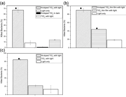
Figure 3-11: Killing ratio of E.coli (105 CFU mL-1) in the presence of N-doped TiO2 nano
material and pure TiO2 nano material after exposure to the halogen lamp and fluorescent
lamp source. (a) Illumination was carried out under halogen lamp at a light density of 3×10⁴
lux for 1 h with nanoparticles (b) Illumination was carried out under halogen lamp at a light
density of 3×10⁴ lux for 15 min with nanothin film (c) llumination was carried out under
fluorescent lamp at a light density of 5000 lux for 18 h with nanothin film. Bacterial solution alone under various light illumination was chosen as control. Bars indicate average value from three independent experiment data. (●p<0.05) ... 81
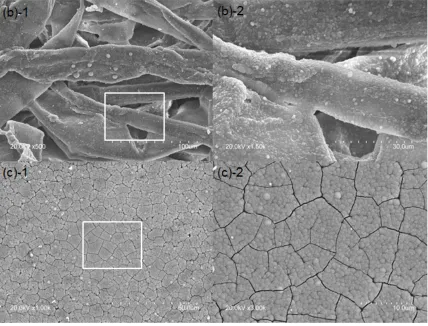
Figure 4-1: SEM images of TiO2 coated on various substrates with different magnification.
(a) LPD-derived TiO2 coating on UV/Ozone treated butyl rubber; (a)-2 zoom in picture in the
white square area of (a); (b) LPD-derived TiO2 coating on pristine cotton sheet; (b)-2 zoom
in picture in the white square area of (b); (c) LPD-derived TiO2 coating on prianha solution
treated silicon wafer; (c)-2 zoom in picture in the white square area of (c); (a)-4 EDX result corresponding to (a)-2, carbon comes from the butyl rubber substrate, and fluorine comes from the LPD solution, Pt comes from the deposited condutive Pt layer. ... 95
Figure 4-2: Optical microscopy of TiO2 coated on butyl rubber substrates after tape test. (a)
LPD-derived TiO2 coating on UV/Ozone treated butyl rubber, (b) after tape test once, (c)
after tape test twice. The circle area showed the changes after tape test. ... 96
Figure 4-3: The XRD patterns of (a)TiO2 coating on butyl rubber surface and (b) TiO2
xvii
Figure 4-4: AFM images of 3D morphology and height images of the TiO2 coating on a butyl
rubber surface deposited by the LPD method. ... 97
Figure 4-5: SEM micrographs of the silicon wafer surface immersed in 0.05 M (NH4)2TiF6
and 0.15 M H3BO3 solution with seed of 0.3 µg mL-1 at 50 oC after (a) 6 h and (b) 12 h. .... 99
Figure 4-6: SEM micrographs of the silicon wafer substrates immersed in 0.05 M (NH4)2TiF6
and 0.15 M H3BO3 solution at 50 oC for 12 h with or without various concentration of seed
(a) without seed, (b) with seed 0.15 µg mL-1, (c) with seed 0.4 µg mL-1, (d) with seed 3 µg
mL-1. ... 100
Figure 4-7: SEM micrographs of the silicon wafer surface immersed in 0.05 M (NH4)2TiF6
and 0.15 M H3BO3 solution at 50 oC for 12 h with (a) PEI modified seed at 2 µg mL-1 (b)
PAA modified seed at 2 µg mL-1. ... 102
Figure 4-8: Typical SEM micrographs of sphere-like TiO2 crystallites on the silicon wafer
surface. ... 103
Figure 4-9: Typical SEM micrograph of TiO2 crystallites formed clusters in sedimentation.
... 103
Figure 4-10: SEM micrographs of the fluorinated silicon wafer surface with coating which
immersed in 0.05 M (NH4)2TiF6 and 0.15 M H3BO3 solution at 50 oC for 6 h with seed at 1µg
mL-1. Optical image of the hexadecane contact angle is inserted in the top-right corner of the
SEM images. (a)-(d) The top view of the surface coating with different magnification. (e)
The cross-section view of the TiO2 particles formed cluster structure. EDX result showed the
chemical composition of the cluster. ... 104
Figure 4-11: Representative SEM micrographs of the silicon wafer substrates with
LPD-derived TiO2 coating after 6 h incubation in E. coli suspensions: (a) pristine LPD-derived
TiO2 coating deposited for 6 h without seed, (b) fluorinated pristine LPD-derived TiO2
coating deposited for 6 h without seed, (c) LPD-derived TiO2 coating deposited for 12 h with
xviii
Figure 5-1: Schematic illustration of the spray apparatus. The spray distance (L) is 15 cm and
the pressure P is 60 psi under room temperature (T=25 oC) and a range of relative humidity
(RH: 40-50%)... 116
Figure 5-2: Representative SEM images at various magnifications showing the surface
morphology of the UV cross-linked coatings with a solute concentration of 12.5 mg mL-1.
The solute concentrations are: (a) 50/50 wt% PIP/CB, (b) 45/55 wt% PIP/CB, (c) 40/60 wt% PIP/CB, and (d) 34/66 wt% PIP/CB. The insets are contact angle images of hexadecane (left) and methanol (right). ... 119
Figure 5-3: SEM images of the UV linked superoleophobic coating (P45C55) in cross-section at different magnification increasing from left to right. The cross-cross-section was produced by freeze-fracturing. ... 120
Figure 5-4: High resolution C (1s) spectrum of a spray coating containing 66% CB. Note the evidence of the –OH functionality on the surface. ... 121
Figure 5-5: SEM images of UV cured coatings sprayed on 6×6 cm2 butyl rubber substrate
(P40C60, 40/60 wt% PIP/CB blends, 12.5 mg mL-1) using different suspension volumes: (a)
50 mL, (b) 25 mL and (c) 15 mL. Optical images of the hexadecane contact angles are given as inserts in the top-right corner of the corresponding surface. ... 123
Figure 5-6: Different magnification SEM images showing the coating morphology before
and after tape test. Sample P40 C60 (40/60 wt% PIP/CB blends, 12.5 mg mL-1) was sprayed
on 6×6cm2 butyl rubber substrate using 25 mL of suspensions. (a) UV cured and before tape
test; (b) UV cured and after tape test; (c) not UV cured and before tape test and (d) not UV cured and after tape test. Optical image of the hexadecane contact angles are inserted in the top-right corner of the SEM images. ... 125
Figure 5-7: SEM morphology of coatings (P50 C50, 50/50 wt% PIP/CB blends, 12.5 mg mL
-1) with different crosslinking methods. (a) HHIC treatment for 2 min treatment (b) UV cured
xix
Figure 5-8: Contact angles of Hexadecane as a function of strain for coatings deposited on butyl rubber substrate. The contact angle measurements were averaged for each data point. ... 128
Figure 5-9: Resistivity of composite coatings on butyl rubber substrate with different CB percentage (12.5 mg mL-1). ... 129
Figure 6-1: XPS survey spectra performed on PEO modified silicon wafer surface in the binding energy range of 0-1100 eV with a pass energy of 80 eV... 142
Figure 6-2: XPS high-resolution C 1s spectrum of PEO control ( (EtO)3Si-(CH2)3
-(OCH2CH2)6~9-OCH3 grafted silicon wafer). The observed C 1s peak was fitted with two
Gaussian peaks at binding energies of 284.99 eV (C-C/C-H), 286.78 eV (C-O). ... 142
Figure 6-3: XPS survey spectra performed on PFTS modified silicon wafer surface in the binding energy range of 0-1100 eV with a pass energy of 80 eV... 143
Figure 6-4: XPS high-resolution C 1s spectrum of PFTS grafted silicon wafer (PFTS control). The observed C 1s peak was fitted with five Gaussian peaks at binding energies of
285.00 eV (C-C/C-H), 286.50 eV (C-O/C-O-C), 288.0 eV (CFx), 290.29 eV (CF2) and
292.76 (CF3). ... 143
Figure 6-5: Plan view for polyisoprene-nanofiller composite coating on PET surface of 33.3 wt% of polyisoprene with different nanofiller loading: (a) CB 6.7 wt%, titanium dioxide 60.3 wt%; (b) CB 13.4 wt%, titanium dioxide 53.6 wt%; (c) CB 33.4 wt%, titanium dioxide 33.3 wt%. Optical image of the hexadecane contact angles are inserted in the top-right corner of the corresponding surface. ... 147
xx
Figure 6-7: (a) Plan view for Polyisoprene-TiO2 composite coating (polyisoprene 33 wt%,
titanium dioxide 67 wt%) on PET surface. (b) the zoom-in image of the area as highlighted by the black circle in (a)... 149
Figure 6-8: Details of a superoleophobic surface coating on PET surface with composition of polyisoprene 40 wt%, CB 30 wt% and titanium dioxide 30 wt% and EDX element mapping. ... 150
Figure 6-9: 2D and 3D AFM togographical images of (a) composite film with the
composition of PIP 40 wt%, CB 30 wt%, titanium dioxide 30 wt%, Rq=500±46 nm.(b)
composite film with the composition of PIP 50 wt%, CB 25 wt%, titanium dioxide 25 wt%,
Rq=375±47 nm. RMS roughness (Rq) of the composite coating surface, defined as the
standard deviation of the elevation, z values. The average RMS roughness value was
determined for responding surface from three different locations... 152
Figure 6-10: Representative fluorescence microscopy graphs of samples immersed in 0.1 mol
L-1 BSA PBS solution surface for 3 h. (a) PCT (PIP 40 wt%, CB 30 wt%, titanium dioxide 30
wt%), (b) FPCT (superoleophobic coatings with the composition of PIP 40 wt%, CB 30 wt%, titanium dioxide 30 wt%)... 154
Figure 6-11: Relative BSA (0.1 mg mL-1) adsorption on various surfaces for 3 h. FPCT
stands for superoleophobic coatings with the composition of PIP 40 wt%, CB 30 wt%, titanium dioxide 30wt%. Fluorinated silicon wafer and PEO silane modified silicon wafer was used as reference. ... 154
Figure 6-12: Representative fluorescence microscopy graphs of samples immersed in 1 mg L
-1 BSA PBS solution surface for 3 h. (a) PCT (PIP 40 wt%, CB 30 wt%, titanium dioxide 30
wt%), (b) FPCT (superoleophobic coatings with the composition of PIP 40 wt%, CB 30 wt%, titanium dioxide 30 wt%)... 155
Figure 6-13: Representative fluorescence microscopy graphs of samples immersed in 0.1 mg
L-1 fibrinogen PBS solution surface for 3 h. (a) PCT (PIP 40 wt%, CB 30 wt%, titanium
xxi
Figure 6-14: Relative fibrinogen (0.1mg mL ) adsorption on various surfaces for 3 h. FPCT
stands for superoleophobic coatings with the composition of PIP 40 wt%, CB 30 wt%, titanium dioxide 30 wt%. Fluorinated silicon wafer and PEO silane modified silicon wafer was used as reference. ... 156
Figure 6-15: SEM images after various coatings immersed in E.coli suspensions (108 CFU
mL-1) for 24 h at different magnification: (a) pristine PET substrate, (b) FPCT composite
coating on PET substrate, (c) pristine PCT composite coating on PET substrate. ... 159
Figure 6-16: SEM images of various coatings after dynamic growth using a parallel-plate
flow chamber with E coli 108 CFU mL-1 for 24 h (shear rate 3.6 s-1). (a) pristine PET
substrate, (b) FPCT composite coating on PET substrate, (c) pristine PCT composite coatings on PET substrate. ... 160
Figure 6-17: Representative fluorescence microscopy images of attached E.coli cells from a
suspension with 108 CFU mL-1 for 24 h dynamic growth. Bacterial cells were stained with
Chapter 1
1 General introduction
1.1 Problems of biofouling in the environment and biomedical field
Microorganisms are found everywhere in our daily life and most are harmless. However, humans and animals can be infected by microorganisms, such as bacteria, yeast, spores, and viruses, which may come from contaminated food and other sources. Common surfaces such as doorknobs, key boards and cell phones being constantly touched by hands, and ceramic tile in public washrooms are all compatible places for bacteria to grow and spread. Door handles and ceramic tiles themselves normally do not have antibacterial activity and microorganisms easily breed on their surfaces, resulting in biofilm formation and bacterial spread. These areas can serve as reservoirs of microbes for the transfer of infections. Public places, such as schools and hospitals, are risk areas for infection when children and patients may be vulnerable due to a weakened immune system. Disinfection is crucial to prevent infectious diseases.
Staphylococcus bacteria are known as a major cause of both hospital-acquired and community-based infections [6]. Coagulase-negative staphylococci (CoNS) that secrete bacterial slime (a polysaccharide) and form a biofilm firmly adhering on surfaces, are by far the most common cause of bacteremia related to indwelling devices [7]. Particularly, the bacteria Escherichia coli (E.coli) have been recognized as a significant cause of catheter infections [8]. Since the first report about drug resistance in Staphylococci aureus (S.aureus) in early 1960s [9], the increasing rate of drug resistance among S.aureus and CoNS species has been reported. In addition, S.aureus and CoNS, particularly those strains acquired in hospital, have become resistant to multiple antimicrobial agents [6].
Disinfectants to kill microbes are widely used in hospitals and other health care settings for a variety of topical and hard-surface applications. They are non-selective towards microorganisms in a broader spectrum of biocide ability, compared to antibiotics which are essential to prevent nonsocomial infection. A variety of active chemical agents including alcohols, iodine, chlorine and triclosan have been used for a long time in disinfection. However, the use of chemical disinfectants is accompanied by the risk of allergic reactions and toxicity to humans. The traditional surface cleaning procedures might not be sufficient to remove formed biofilms and kill attached bacteria [10]. Due to the outbreak of infectious diseases caused by different pathogenic bacteria and the emergence of more-resistant microorganism owing to widespread use of antibiotics, more rigorous hygienic standards in public areas and hospitals are being promoted [11]. There is an urgent need to develop alternative efficient and sustainable antibacterial strategies, which are non-toxic and green (i.e. environmentally compatible and biodegradable).
1.2 Principle of Biofouling
1.2.1 Protein adsorption
Biofouling is a dynamic process, in the form of protein, and bacterial attachment on a solid surface. When biomedical materials contact biological fluids such as blood, serum proteins regulate the process of bacterial adhesion [12], and protein adsorption is the first stage. A material surface that resists the adsorption of protein is normally a good candidate to resist bacterial adhesion [13]. Generally, proteins include serum proteins, enzymes, antibodies and foreign antigens. They are complex biopolymers composed of amino acids as monomeric units which have highly ordered structures. The approaching of protein molecules to the interface is driven by diffusion processes, which is dependent on the bulk concentration and the appropriate diffusion coefficient [14]. Protein
adsorption spontaneously occurs if Gibbs free energy of the system decreases, ∆adsG =
∆adsH−T∆adsS < 0, where G, H, S and T are the Gibbs free energy, enthalpy, entropy and
the absolute temperature, respectively. ∆ads represents the change of the thermodynamic
function. Partial or complete conformational changes lead to an increase in conformational entropy, providing the driving force for protein adsorption. In contrast to small rigid molecules that can simply attach to or detach from an interface with certain adsorption and desorption probabilities, the irreversible adsorption of proteins is generally observed, owing to complex composition and structure of protein [15]. Protein at interfaces affects a wide variety of phenomena, including mammalian cell growth, reactions to implanted biomaterials, the formation of organized layers of protein and growth of bacteria [16]. Often protein adsorption onto a surface is energetically favorable to reduce the interfacial energy.
The environment of the solution in which the protein adsorption experiments are conducted, including pH, ionic strength, temperature and buffer composition, have significant effects on adsorption behaviour. Under mimicked physiological conditions, the environmental parameters of the solution are fixed. Furthermore, various proteins with remarkably diverse characteristics like size, structural stability and composition, have different behaviours on solid surfaces. For small and rigid proteins such as
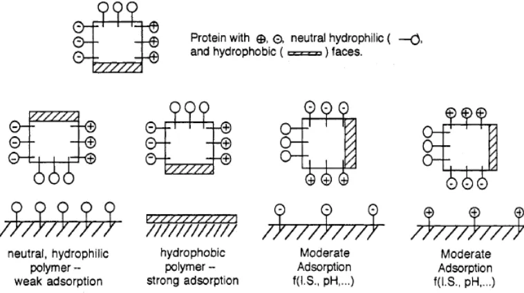
adsorption [17-19]. For high-abundance plasma proteins such as albumin, transferrin and immunoglobulin, the conformational reorientations occur in the course of surface adsorption [20]. The class of proteins with high molecular weight shows a strong affinity to hydrophobic surfaces with significant conformational reorientation owing to the large content of lipids or glycans in the structure [21]. Fig 1-1 illustrates the possible collision of protein to surface. The affinity of protein to any surface is determined by its independent acting domains.
Figure 1-1: Schematic view of simplification of protein model, with hydrophobic,
neutral hydrophilic, negatively and positively charged domains (sides). The
adsorption occurred on the domains that can interact with a surface having
comparable properties. Reproduced from Reference [14].
properties [23-29]. In most case, protein adsorption increases on hydrophobic substrates and decreases on hydrophilic substrates. As indicated in Fig 1.1, the non-polar surfaces destabilize proteins and facilitate conformational reorientations due to the strong hydrophobic interactions [25]. In general, proteins tend to adhere more strongly to nonpolar surfaces than to polar ones, to high surface tension rather than to low surface tension surfaces and to charged rather than to uncharged surfaces [20].
The kinetics of protein adsorption is complicated, including factors such as surface diffusion, aggregation and conformational changes, which are sensitive to surface properties. For example, many investigations studied the effect of surface morphology on protein adsorption both experimentally and theoretically [30-33]. The overall effect of nano-topographic factors, including roughness, curvature and geometry, on protein adsorption is still not clear according to the recent reports. Cai et al. [34] studied the
protein adsorption of titanium films with different topographies (2 nm < Rrms < 21 nm)
produced by electron beam deposition. The protein adsorption results (with albumin and fibrinogen) indicated that nano-scale roughness had little effect. Han et al. [35] also
reported that there was no obvious correlation between roughness (5 nm < Rave < 60 nm)
Surface curvature as a measure of topography also influences protein-surface interaction. Lundqvist et al. [38] analyzed the adsorption of human carbonic anhydrase, a globular protein of comparable size to albumin, to the surface of silica nanoparticles with various diameters (6 to 15 nm) and found that particles with a larger diameter caused more perturbations of the protein secondary structure owing to larger particle–protein interaction surfaces. The same effect has also been reported from studies of the adsorption of egg lysozyme on silica nanoparticles of varying size (4, 20 and 100 nm)
[39]. The author also reported that more α-helix structure of protein was lost on large
silica nanoparticles. It is suggested that the decreased curvature of larger nanoparticles produced a shorter distance from the silica surface to the protein molecule and caused stronger interaction (Columbic and hydrophobic interaction). In contrast to small globular proteins, bigger conformational changes of fibrinogen on smaller nanoparticles (radius less than 30 nm) have been observed [40]. More studies are needed involving a broader range of proteins and different surfaces to explore the effect of curvature on protein adsorption.
Current literatures suggested that the surface morphology and nano-scale roughness have influence on protein adsorption to the surface on the amount of adsorption, conformation change. More experimental results are needed in order to draw general conclusions.
1.2.2 Bacterial adhesion
Figure 1-2: Scheme of biofilm development. Reproduced from Reference [43].
Figure 1-3: Scheme of the biofilm development. Details of the step 2 in the bacterial
adhesion process. Reproduced from Reference[43].
between bacteria and a surface through a selective bridging function of bacterial surface polymeric structures including capsules, fimbriae/pili and slime. [44].
Bacterial adhesion is a complicated process that is affected by many factors, including the environment, the presence of serum proteins or bactericidal substances, the properties of the target surface and the intrinsic characteristics of the bacteria itself [44]. Our focus is on how the properties of surfaces influence bacterial adhesion.
Surface properties, e.g. material hydrophobicity and surface charge, influence bacterial adhesion. Generally, bacteria with hydrophobic properties prefer hydrophobic surfaces, while bacteria with hydrophilic characteristics prefer hydrophilic surfaces [44, 51]. Hydrophilic materials are more resistant to bacterial adhesion than hydrophobic materials [44, 52-54]. Bacterial adhesion is hindered by surface modification with ethylene glycol (EG) monolayer. The EG provides a template for water nucleation and forms a stable interfacial hydration layer [55, 56]. Bacteria in aqueous suspension are always negatively charged [57]. It was reported that the tested bacterial strains adhered rapidly to positively charged surfaces, although no subsequent growth of the Gram-negative strains was observed [58]. Long-range electrostatic forces may influence the initial phase of bacterial adhesion; positively charged surface can only inhibit growth of some adhered bacteria. Surfaces with bactericidal substances displayed a decreased adhesion [59-63].
Surfaces of the same materials and surface chemistry may have different bacterial attachment affinity in the same environmental conditions owing to different surface topography [45]. It has been shown that in general surfaces with higher roughness promote better bacterial adhesion owing to the greater surface area compare to smoother surface [64, 65]. However, Harris et al. [66] found that no differences between the adhesion of S.aureus on micro-scale rough standard titanium and smooth electropolished titanium surfaces under static conditions in vitro. Bacterial adhesion affected by micro-scale surface features has yet to be extensively studied, while few studies addressed the effect of nano-scale topography on bacterial response [67]. In an early work [68], a small
increase in Ra values (0.04-1.24 µm, the surface roughness of a substratum was evaluated
compared to a larger increase of surface roughness (Ra=1.86-7.89 µm), although both
adhesion values were higher than on smooth surfaces. A similar non-linear relationship between bacteria adhesion to the increase of roughness has been obtained by using AFM to measure the surface roughness and bacteria adhesion image [69]. More bacteria adhesion on a modified nano-scale smooth surface with an average surface roughness of 1.3 nm than the native sample surface with an average roughness of 2.1 nm was observed. This inverse relationship manifested that bacteria might be more susceptible to nano-scale surface roughness. The surface nanotopography was also found to stimulate the exerting of bacterial exopolysaccharide (EPS), which promote adhesion [70]. Furthermore, the surfaces with certain pattern or some hierarchical structure roughness might possess superhydrophobic wettability. These surfaces with self-cleaning ability demonstrated resistance to bacterial adhesion [71, 72]. Discussion of these concepts follows in later sections.
1.3 Strategies to prepare antifouling surface
Several strategies have been developed to fabricate antifouling surfaces or to overcome problems of biofouling on surfaces, such as the chemical modification involving biocidal agents and fouling release coatings, and the introduction of surface modified coatings with appropriate surface patterns and structures. Herein, methodologies towards preparing antifouling coatings are reviewed and those methods are basically categorized into two directions: 1) active methods, with intrinsic bactericidal properties such as metal and metallic oxide nanoparticles, carbon nanotubes and fullerenes, polycations (chitosan) and polysaccharide (antimicrobial peptides) and 2) passive methods, showing resistance to the adhesion of microorganisms including hydrophilic and superhydrophobic surfaces.
1.3.1 Active antifouling coatings
size effects and surface phenomena at the nano-scale. A variety of metallic nanoparticles and compounds with bacteriostatic and bactericidal properties have been reported including copper [74-78], zinc oxide [79-82], magnesium oxide [59, 83], iron [84, 85],
iron oxide [86-88] and titanium oxide (TiO2) [89]. Production of reactive oxygen species
(ROS) or heavy metal ions, which would result in oxidative damage to bacterial membranes, proteins and DNA, is the main mechanisms of antibacterial activity of metal oxides [59, 90, 91]. In addition, penetration of metal oxide nanoparticles into cells [59], electrostatic interactions [53] as mechanism of antibacterial activity have also been proposed. Among the metal with antibacterial properties, silver is the most promising and potent agents [81, 92].
Figure 1-4: Schematic photoexcitation on TiO2 after UV excitation. Reproduced
from Reference [96].
TiO2 is one of the most effective photocatalysts because of its strong oxidizing power,
non-toxicity and long-term photostability. It is well-known that photocatalytic activity is strongly related to the physical properties including crystallinity, crystal structure,
particle size, specific surface area (SSA) and morphology. As reported, TiO2 has three
main types of crystalline structures, known as anatase (tetragonal, band gap = 3.2 eV, which is equivalent to a wavelength of 388 nm), rutile (tetragonal, band gap = 3.02 eV) and brookite (orthorhombic, band gap = 2.96 eV) [97]. Anatase and brookite are thermodynamically metastable phases at lower temperatures and the bulk rutile is the most thermodynamically stable polymorph. An irreversible phase transition from brookite to anatase and to rutile usually occurs with increasing temperature [98]. Anatase and rutile phase are commonly used as photocatalysts, and most practical work has been carried out with either rutile or anatase [96]. In contrast, brookite has attracted much less interest due to the generally considered lack of photocatalytic activity, although continuing studies have shown that brookite is photocatalytically active [99].
TiO2 as a photocatalyst has been extensively studied over recent decades for the strong
oxidizing power when illuminated by UV light with wavelength <385 nm. When light
electron-hole pairs are generated at the surface of the TiO2. Upon excitation, the photoinduced
electron-hole pair is separated into a free electron and a free hole. The electron and hole either transfer to the surface of the photocatalyst or trapped there. Fig. 1-4 shows the electron-hole excitation process, characteristic surface reaction and some of the de-excitation pathways [96]. At the surface, the electron can transfer to atmospheric oxygen
to form superoxide ions (O2•-) and holes can react with adsorbed H2O or OH- at the
catalyst/water interface to produce the highly reactive hydroxyl radicals (•OH). The
photocatalytic process generates reactive oxygen species (ROS) such as hydroxyl radical
(•OH), hydrogen peroxide (H2O2) and superoxide (O2•-) which can oxidize and
decompose many types of organic compounds and microbial organisms, such as cancer cells, viruses and bacteria [100-102]. Complete oxidation of organic compounds and whole cells to carbon dioxide can be achieved without crating secondary pollution [103]. Moreover, it also simultaneously degrades the toxic compounds released from the bacteria [104].
With excellent chemical stability, low cost and non-toxicity, TiO2 became attractive for
practical applications. Since 1985, the first report about that TiO2 photocatalyst could kill
bacterial cells in water, a variety of research works have been carried out related to the
bactericidal effect of TiO2 photocatalyst [89]. Fig. 1-5 schematically illustrates the
process of photodegradation of bacterial cells. Hydroxyl radicals produced during the
illumination process on TiO2 surfaces may harm cellular macromolecules (e.g. lipids,
proteins and nuclei acids) and promote other deleterious changes in bacterial cells (e.g. phospholipids peroxidation) [105]. The loss of bacterial respiratory activity owing to oxidation/reduction of the intracellular Coenzyme A (CoA) will cause bacteria death. If
the TiO2 particles are sufficiently small, they can penetrate the cell and implement the
photocatalytic process inside and directly attack intracellular components [105]. Most
studies reported the killing or inhibition of bacteria growth by using TiO2 nanoparticles
owing to the very large surface area and high efficiency. Lu et al. [106] have reported a
possible bactericidal mechanism of the illuminated TiO2 thin film. The cell wall was
Figure 1-5: The photodegradation of bacteria. Reproduced from Reference [105].
Considering to expand the application field to indoor condition in the absence of UV-light and to utilize the solar energy efficiently, it is necessary to develop titania with photoresponse capacity within the visible range. Several methods have been used to improve the photocatalytic properties and antibacterial activities, including the reduce form of the band gap energy via surface modification with metal or another semiconductor and the generation of a defect structure to induce space-charge separation through metal or non-metal dopants. For instance, Yu et al. [107] described that 96.7%
Gram positive bacterium Micrococcus lylae (3×10⁶ CFU mL-1) were killed by S-doped
TiO2 nanoparticles after 1 hour visible light illumination (100 W tungsten halogen lamp
with 420nm filter). The doping of commercial TiO2 powder with nitrogen and sulfur by
direct heating the mixture of TiO2 with thiourea showed high photocatalytic activity
towards E.coli inactivation (~104 CFU mL-1) under blue light illumination [108]. Li et al
reported enhanced photodisinfection of E. coli by using carbon and nitrogen co-doped
TiO2 [109]. The addition of noble metals such as gold and silver as electron trapper to
of TiO2 co-doped with nitrogen and silver. The resultant co-doped powder samples
showed the survival fraction of E. coli <10-5 within approx. 30 min irradiation, which is
fastest ever reported using TiO2 based photocatalyts.
Compared to the application of nanopowders, which in some practical applications require extra nanopowder filtration and recollection processes and have the potential environmental pollution risk, the form of a thin film is more favourable. Many techniques have been developed to coat surfaces with photocatalyts including wet methods such as sol-gel and spraying, or dry processes, such as ion-assisted electron beam evaporation, reactive sputtering, pulsed laser deposition and chemical vapour deposition [111-117].
Shieh et al. [115] developed a defective TiO2 thin film on glass and steel substrates using
radiofrequency sputter technique. They demonstrated a stronger antibacterial
performance against E.coli than plain TiO2 nanoparticles, with a killing efficiency of
approximately 99.99% versus 50% under 5 h illumination of four 15 W fluorescent lamps. Wong et al. [114] demonstrated disinfection of various bacterial strains using
nitrogen-doped TiO2 films and carbon-doped TiO2 films, prepared in an ion-assisted
electron bean evaporation system. The study showed that nitrogen-doped TiO2 films had
better visible light photocatalytic bactericidal activity against human pathogens than TiO2
film and carbon-doped TiO2 films. Several pathogens also showed resistance against
ROS attributed to the presence of the enzyme system. The presence of protein such as BSA or dye contaminant in the solution will inhibit the antibacterial performance. The mechanism remains to be further investigated.
Gram-negative bacteira E.coli and Gram-positive bacteria S.aureus are two commonlt used organism models in antimicrobial tests. Although some researches claimed that E.coli is more easily deactivated under photocatalytic reaction than S.aureus caused by the thinner cell wall [118], it should be noted that S.aureus is more light sensitive and spontaneously exhibits a high kill rate purely from the light source [119], while Gram negative bacteria are far less susceptible to light-activated antimicrobial agents [120].
Therefore, E.coli is harder to kill than S.aureus [121]. The antibacterial activities of TiO2
conditions for photocatalytic inactivation of bacteria, a direct comparison among the
reported photosterilization activity data of TiO2 under UV or under visible light
irradiation is not realistic. However, N-doped TiO2 is less effective than the pure TiO2
under UV light irradiation, because the recombination sites from the dopant ions lead to the faster recombination of the electron-hole pairs, preventing the antimicrobial effects [121].
Carbon nanotubes (CNTs) and graphene have attracted great attention owing to the unique electrical properties and structural characteristics. CNTs with high surface areas
and strong adsorption capacities as an effective dopant to TiO2 based photocatalytic
materials give rise to the enhanced visible light photocatalytic performance and improved bacterial inactivation [122]. CNT nanocomposites were reported to be resistant to protein adsorption [123]. Graphene-based nanomaterials (graphene oxide GO) also suppressed the growth of E.coli with mild cytotoxicity [124]. The antibacterial activity was attributed to the membrane stress induced by sharp edges of graphene nanosheets, leading to the damage of cell membranes and leakage of RNA [125].
1.3.2 Passive antifouling coatings
The surface chemistry of a solid substrate is one of key determinants of the initial adhesion, formation, stability and release of adhesion of fouling organisms to a surface [126]. Surface energy, mechanical properties and wettability also play an important role in the surface resistance to biofouling [127]. A general relationship (Baier curve) between surface tension and the relative amount of bioadhesion demonstrates that the minimal fouling is at a critical surface tension of 22-24 mN m-1, which is equal to the cost for
water rewet the surface [126]. One method of varying surface energy without changing the bulk materials is through surface modification by introducing materials fall above the zone of low cell adhesion defined by Baier.
In recent years, the polymer modification on various substrates to construct the antifouling surfaces has attracted much attention, especially after the development of
surface initiated living radical polymerization techniques, e.g. reversible
polymerization (ATRP). The advantages of the polymer modification include, 1) low cost of the abundant available monomers; 2) the well-defined surface chemistry of polymers; 3) the facile surface patterning as a means to construct various nanostructures on
substrates; and 4) the advanced functionalities of polymers, e.g. stimuli-responsive
polymers. In general, the adhesion strength of bioactive molecules to polymer surfaces
(A) is dependent on the polymer modulus (E) and surface energy (ɤ), A~(Eɤ)0.5 [128].
As a consequence, a number of polymers having low surface energy, including poly(ethylene glycol) (PEG), fluoride poly(methyl)acrylates, zwitterionic polymers, and polyelectrolytes, have been investigated for antifouling surface coating; besides, the low
modulus polymers, e.g. poly(dimethylsiloxane) (PDMS) and polyurethane (PU) have
been studied for the fouling release properties.
PEG with rather low polymer-water interfacial energy (σ < 5 mJ m-2) is a completely
biocompatible polymer and has been widely used in biomedical industries [129]. The antifouling property of PEG modified substrates was firstly revealed in the studies of self-assembled monolayers (SAMs) of oligo (ethylene glycol) functionalized alkanethiolates on Au films by Prime and Whitesides [130]. SAMs composed of
HS(CH2)11(OCH2CH2)6OH and HS(CH2)11CH3 strongly prevented the protein adsorption
effect of PEG chain density on the nonfouling properties [135]. At high grafting density, the PEG grafts in the brush state detached from the substrate and had the highest resistance to the protein adsorption; while, the decrease of PEG grafting density that gave rise to the mushroom conformation of polymer chains on the substrate, resulted in the increase of protein attachment. However, the stability of PEG in biomedical environment limits the in vivo application, due to the autoxidation of PEG in the presence of transition metal ions and oxygen radicals.
Figure 1-6: The chemical structures of polymers for antifouling coating.
Polycations are known for the antibacterial and anti-cell adhesion properties in solution due to their diffusion across the bacterial membranes and disruption of the membranes. Due to the bactericidal ability, they should be categorized as active agents for antibacterial adhesion. However, we mentioned them in this section because of their polymer intrinsic properties. A number of polymers with primary, secondary or tertiary
amine groups (e.g. poly(4-vinyl pyridine) (P4VP), poly(2-dimethylaminoethyl
Other than the low surface energy polymers, the fouling release properties of low modulus polymers are of interest in the field of bioimplants, artificial vessels and biomimic devices that serve in dynamic fluids [143-145]. The apolar surfaces of the rubbers or elastomers (e.g. silicone, PDMS and PU) can easily be attached by proteins or bacteria in aqueous media, whereas such surfaces have low modulus that result in the easy detaching of proteins or bacteria under hydrodynamic forces [129]. As these polymers are environmentally friendly, the possible application of these polymers for the marine bio-antifouling coating has been intensively studied. Callow et al. studied the effect of PDMS film modulus and thickness on the fouling release of spores by varying the cross-linking density of PDMS [143]. The detaching of spores only occurred at the modulus ~0.2 MPa. To improve the adhesion and antifouling properties of PDMS coating to substrates, the copolymers of PDMS/PU or PDMS/polyacrylates have been investigated [146, 147].
In contrast to complete wetting surface, which forms the hydrated interfacial layer, the other approach to prevent microbes coming into contact with the surfaces is developing superhydrophobic or superoleophobic surfaces.
Static contact angle θ (CA) is the primary parameter and the most straightforward method
LA SL SA flat γ γ γ θ )= − cos( (1)
where γ is the surface energy or surface tension, subscripts S stands for solid, L stands for
liquid and A stands for air. The solid-liquid surface energy can be approximately
estimated by the other two as follows [148]:
LA SA LA
SA
SL γ γ γ γ
γ = + −2 (2)
If the liquid wets the surface, the value of the static contact angle is 0 ≤ θ≤ 90o and the
corresponding surface is hygrophilic (where the prefix hygro means liquid in Greek, can be replaced by hydro-, oleo-, etc., depending on the wetting liquid) [149], whereas if the
liquid does not wet the surface, the value of the contact angle is 90o < θ≤ 180o and the
corresponding surface is called hygrophobic For water (surface energy γLA = 73 mJ m-2)
the best non-wetting situation on a flat surface is achieved by terminated with the -CF3
group, which lowers the surface energy to γSA ~ 6 mJ m-2. The value of the intrinsic
(Young’s) CA for water on such a surface is θflat ~ 120o which is close to the estimation
via Eqs.(1) and (2) [150]. By contrast, many organic liquids such as oils and alcohols
have very low surface energies (e.g. γLA = 27.6 mJ m-2 for hexadecane, γLA = 22.5 mJ m-2
for methanol). Consequently, even on the chemically least energetic surface terminated
with -CF3 groups, the intrinsic CA for typical oils such as hexadecane is θflat ~ 78o. In
other words, all flat solid surfaces in nature are intrinsically oleophilic (in terms of the Young’s CA) no matter their chemical compositions. This circumstance has profound consequences on the design of super-oleophobic surfaces, as we describe in more detail below.
surface [152]. Surfaces with a CA of less than 10o are called superhygrophilic, while surfaces with both advancing and receding contact angle for liquid droplet exceed a value
of 140o called superhygrophobic [153]. Such a superhygrophobic surface is also
characterized by a low CAH, which has a common qualitative feature that liquid droplets do not stick to such a surface and easily roll off from the surface when the surface is titled. The definition of superoleophobic is high CA for organic liquids with low hysteresis.
A multitude of wetting behaviours on surfaces can be divided into two major classes (1) homogenous and (2) heterogeneous. Two theoretical models are widely used to explain the wettability phenomena of surfaces. Homogenous wetting is where the liquid wets all the details of a rough surface and is described by the Wentzel’s model [154] In the
Wentzel’s model, the roughness r (r > 1) of a surface is known to amplify both its
hygrophobicity and hygrophilicity, comparing to a chemically identical and flat surface:
) cos( )
cos(θrough =r θflat (3)
According to the Eq.(3), both hygrophobicity and hygrophilicity are enhanced by roughness, θadv < θflat , in the hygrophilic case (θflat < 90o); and on the other side, θadv >
θflat , in the hygrophobic case (θflat > 90o). However, the receding contact angle is very
low in the Wenzel state, and consequently has a very high CAH because the liquid droplets remain pinned in the roughness valleys.
The second class of wetting behaviour is heterogeneous wetting and is described by the Cassie-Baxter model [155], where the liquid droplets only contact the top of the
roughness asperities, staying in contact with a fraction f1 of the rough solid surface. The
2 1
rough) cos( )
cos(θ = f θflat − f with f1+f2≥ 1 (4)
where f1 is defined as the total area of solid under the drop per unit projected area under
the drop, with θflat is the CA on a smooth surface of material 1, f2 defined in an analogous
way with material 2 as air (θ2 = 180o) [156].
Figure 1-7: Three different wetting models. (1) Young’s model, (2 ) Wenzel model
and (3) Cassie-Baxter model.
As described in Cassie-Baxter model, one can achieve very high apparent CA with low f1,
which implicitly assumes the CAH is low. It is easy to realize the Cassie-Baxter state in the case of water on the surfaces which are intrinsically hydrophobic (θflat > 90o for water). In such a case, a hydrophobic material has higher surface energy when it is wet than when it is dry; Water does not penetrate the rough valleys because it is energetically unfavourable [157, 158]. It is not surprising that there exist a large number of known superhydrophobic surfaces discovered in nature (such as the lotus leaf [159] and water strider’s leg [160]) and artificial structures [161] but superoleophobic surfaces are still extremely rare in nature [162].
It is easy to see why superoleophobic surfaces are exotic. If a surface is intrinsically
hygrophilic when flat (θflat < 90o, which is typical for most oils on flat natural surfaces),
However, low-surface energy liquid droplets such as oil (θflat < 90o) can be kept in the metastable Cassie-Baxter state for a sufficient long time, showing that some local stability criteria for a liquid-solid contact line are met [149, 157, 163]. While a detailed description of these conditions is out of scope of the present work, here we only note that:
(i) the intrinsic CA at the contact line must be equal to the value at flat surface θflat; (ii)
parts of the roughness asperities where the contact line finds a stable position must be of a convex shape. It has been shown [149, 164], that for low-surface energy oil-like liquids
(θflat < 90o) the above conditions can be satisfied in the case when surface morphology
bears some “over-hanging” or “re-entrant” features [162, 165-167]. However, to reduce
the fraction f of a rough surface in contact with a liquid in Eq. (4), such a surface must
possess rough features on a multiple scale, ideally like a fractal [164].
colonize on the lotus-like Ti surfaces [172]. Truong et al. also found four different bacteria attached to the lotus-like Ti surfaces after 1 h immersion period due to the replacement of trapped air by the incubation medium [173].
Compared to superhydrophobic surface, superoleophobic surface is relative harder to achieve owing to critical requirement on the structure parameters. Some superoleophobic surfaces have been developed by the creation of re-entrant or overhanging features and multi-scale hierarchical structures [162, 165-167, 174-179]. Most of these research focused on propose fabrication processes and few studies have considered the applications such as antifouling from biological and organic contaminants.
1.4 Scope of the thesis
The overall objectives of the research work presented in this thesis are to develop strategies and methodologies to fabricate nanostructured materials and composite
materials which have the ability to resist bacterial adhesion. TiO2 is identified as a unique
material with significant potential owing to its excellent photocatalytic ability, chemical inert property and because it is environmentally friendly. The self-sterilizing property
also gives TiO2 materials have many fascinating applications. In particularly, we have
synthesized active antibacterial TiO2 nanomaterials that kill bacteria under UV
illumination or in the dark. A green and low-cost method to involve silver nanoparticles
in TiO2 nanothin film matrix to enhance the antibacterial property has been investigated.
Furthermore, we have synthesised nitrogen doped TiO2 nanomaterials (nanoparticles and
nanothin film) to promote the antibacterial properties to visible light range. By applying liquid phase deposition (LPD) method through the control of nucleation process by
adding seed, TiO2 coatings with controllable structures have been achieved. More
In Chapter 2 and Chapter 3, active component was involved to fabricate antifouling
surfaces. We developed a strategy to prepare TiO2 nanothin film on silicon wafers with
various silver content. Nitrogen doped TiO2 nanomaterials have also been prepared to
expand the application field to visible light range and to utilize the solar energy efficiently. The morphology of the resultant nanomaterials was controllable by tuning the molar ratio composition in the precursor solution. Different characterization methods were used to analyze the prepared films and nanoparticles. The antibacterial ability of the obtained thin films and nanoparticles on Gram-negative bacteria was tested.
In Chapter 4, TiO2 coatings were deposited on the interested substrates, such as butyl
rubber, silicon wafer and cotton sheet, at mild environmental conditions by using the LPD approach. SEM and AFM have been used to observe the surface morphology of the resultant coatings. The morphology of the thin film can be controlled by tuning the
solution composition which, in principle, tunes the formation mechanism of TiO2 film.
After surface fluorination treatment, the TiO2 coatings with hierarchical structure became
superoleophobic. Furthermore, preliminary results on antibacterial adhesion have been explored.
In Chapter 5, we described an easy method to fabricate superoleophobic and conductive dual-functional coatings which are also flexible and stretchable. The durability of the resultant nanocomposite coatings have been tested by tape test. The conductivity and wettability as the function of stretch was measured. In the work described in Chapter 6,
the same design principle of superoleophobic surface was applied to involving TiO2 as
another nanoparticle loading. The formed structures were characterized and process was optimized. The distribution of the nanofillers and surface roughness of the resultant composite coatings was further investigated. The resultant superoleophobic surfaces are evaluated regarding their non-fouling performance by resisting protein adsorption as well as bacterial adhesion.
![Figure 1-2: Scheme of biofilm development. Reproduced from Reference [43].](https://thumb-us.123doks.com/thumbv2/123dok_us/7794331.1292613/29.612.111.537.75.285/figure-scheme-biofilm-development-reproduced-reference.webp)