Electronic Thesis and Dissertation Repository
8-21-2014 12:00 AM
Comprehensive STATCOM Control For Distribution And
Comprehensive STATCOM Control For Distribution And
Transmission System Applications
Transmission System Applications
Shubham Gupta
The University of Western Ontario
Supervisor
Dr. Rajiv K. Varma
The University of Western Ontario
Graduate Program in Electrical and Computer Engineering
A thesis submitted in partial fulfillment of the requirements for the degree in Master of Engineering Science
© Shubham Gupta 2014
Follow this and additional works at: https://ir.lib.uwo.ca/etd
Part of the Controls and Control Theory Commons, and the Power and Energy Commons
Recommended Citation Recommended Citation
Gupta, Shubham, "Comprehensive STATCOM Control For Distribution And Transmission System Applications" (2014). Electronic Thesis and Dissertation Repository. 2214.
https://ir.lib.uwo.ca/etd/2214
This Dissertation/Thesis is brought to you for free and open access by Scholarship@Western. It has been accepted for inclusion in Electronic Thesis and Dissertation Repository by an authorized administrator of
(Thesis format: Monograph)
by
Shubham Gupta
Graduate Program in Electrical and Computer Engineering
A thesis submitted in partial fulfillment of the requirements for the degree of
Master of Engineering Science
The School of Graduate and Postdoctoral Studies The University of Western Ontario
London, Ontario, Canada
ii
This thesis presents the development of a comprehensive STATCOM controller for load compensation, voltage regulation and voltage balancing in electric power distribution and transmission networks. The behavior of this controller is first validated with published results. Subsequently, the performance of this STATCOM controller is examined in a realistic Hydro One distribution feeder for accomplishing the compensation of both mildly and grossly unbalanced loads, and balancing of network voltages using PSCAD/EMTDC software. The STATCOM voltage control function is utilized for increasing the connectivity of wind plants in the same distribution feeder. The thesis further presents a frequency scanning technique for simple and rapid identification of the potential of subsynchronous resonance in induction generator based wind farms connected to series compensated lines, utilizing MATLAB software. This technique is validated by published eigenvalue analysis results. The voltage control performance of the developed comprehensive STATCOM controller is then demonstrated for different scenarios in the modified IEEE First SSR Benchmark transmission system for mitigating subsynchronous resonance in series compensated wind farms using industry grade PSCAD/EMTDC software.
Keywords
iii
Dedicated to my
iv
This work is carried out in the light of Memorandum of Understanding (MOU) signed between University of Western Ontario, Canada and Indian Institute of Technology Roorkee, India. The financial support by Hydro One is greatly acknowledged.
I would like to express my deep and sincere gratitude to my supervisor, Dr. Rajiv K. Varma, for his valuable and constructive guidance during the planning and development of this research work. No words are adequate to express my gratefulness for invaluable advices and paramount support. I consider myself fortunate to learn and work under his supervision.
I am also obliged to Dr. S.P. Gupta for his sincere support throughout this program. I would also like to thank Dr. Pramod Agrawal, Dr. V. Pant, Dr. Dadash Zadeh and Dr. L. J. Brown for providing me deep insight into their courses.
I really feel blessed to work with Dr. Akshaya Moharana. I am thankful to him for providing brotherly support in all difficult situations. I am highly obliged to Mr. GD Gill and Mr. Srinivas for the comfort and making me feel like home during my stay in London.
I wish to express my regards to Dr. A. Bulusu for his continuous motivation to work in the research direction and I hope to meet his expectations in future endeavors. I would like to express my affection to Vishvendra, Devendra, Hemant, Sandeep, Deepesh, Siddhartha, N.N.V. Pratap and the entire Bharat Vandan family and all my IIT Roorkee friends for their continuous support throughout my academics. Words are not enough to express my sincere thankfulness for their unbounded help and care.
I am very much grateful to Nikita, Rohit, Rodney for their encouragement, companionship and support. I would also wish to acknowledge the help provided by lab mates Mansoor, Rohini, Hesam, Vishwajeet, Ehsan, Mahendra, Sridhar and Farukh during this work.
I would like to express my affectionate appreciation to my family for their unwavering faith and continuous encouragement to work hard during my academic education. It would not have been possible without their love.
v
Table of Contents
Table of Contents
Abstract ... ii
Acknowledgments... iv
Table of Contents ... v
List of Tables ... xi
List of Figures ... xii
List of Abbreviations ... xx
List of Appendices ... xx
List of Symbols ... xx
Chapter 1 ... 1
INTRODUCTION ... 1
1.1 LOAD COMPENSATION ... 1
1.2 VOLTAGE UNBALANCE ... 3
1.3 VOLTAGE REGULATION PROBLEM ... 4
1.3.1 Voltage Control to Increase Connectivity of Wind Farms ... 4
1.3.2 Voltage Control to Prevent Subsynchronous Resonance (SSR) in Series Compensated Wind Farms ... 5
1.4 CONVENTIONAL REACTIVE POWER COMPENSATION METHODS... 6
1.4.1 Synchronous Condenser... 6
1.4.2 Static VAR Compensator (SVC) ... 7
1.5 STATIC SYNCHRONOUS COMPENSATOR (STATCOM) ... 9
1.5.1 Configuration ... 9
1.5.2 Operating Characteristics ... 10
vi
1.7 SSR WITH WIND FARM ... 14
1.8 MOTIVATION AND OBJECTIVE OF THESIS ... 15
1.9 OUTLINE OF THESIS... 16
Chapter 2 ... 18
STATCOM CONTROLLER DESIGN FOR BALANCED AND UNBALANCED NETWORK ... 18
2.1 INTRODUCTION ... 18
2.2 STATCOM CONTROL IN BALANCED NETWORK... 18
2.2.1 abc to dq Frame Transformation... 19
2.2.2 Modeling of STATCOM connected to a Grid ... 21
2.2.3 Basic STATCOM Type I Controller... 23
2.2.4 Phase Locked Loop (PLL) Design ... 23
2.2.5 Control of Real and Reactive Power Output from VSI ... 24
2.2.6 VSI Output Voltage Vector in Synchronous Rotating Reference frame . 25 2.2.7 Inner Current Control Loop (VSI Current Control) ... 26
2.2.8 SPWM Technique ... 28
2.2.9 DC Link Voltage Control... 29
2.2.10 Voltage Regulation and Power Factor Correction ... 30
2.2.11 Modification of Controller due to Transformer ... 31
2.3 STATCOM CONTROL IN UNBALANCED NETWORK ... 33
2.3.1 Decomposition into Symmetrical Components ... 33
2.3.2 Separation of Sequence Components Using All Pass Filter ... 34
2.3.3 Negative Sequence Current Control Loop ... 37
2.3.4 SPWM Technique for Unbalanced Control of STATCOM ... 38
vii
Transformer... 39
2.4 COMPREHENSIVE STATCOM CONTROLLER ... 40
2.4.1 Load Compensation ... 40
2.4.2 Voltage Regulation ... 41
2.4.3 Temporary Overvoltage (TOV) Regulation... 42
2.4.4 Voltage Regulation and Voltage Balancing ... 43
2.5 CONCLUSION ... 44
Chapter 3 ... 45
ASSESSMENT OF COMPREHENSIVE CONTROLLER FOR LOAD COMPENSATION, VOLTAGE BALANCING AND VOLTAGE REGULATION . 45 3.1 INTRODUCTION ... 45
3.2 CASE STUDY 1 ... 46
3.2.1 Study System-1 Description ... 46
3.2.2 Selection of Controller Parameters ... 52
3.3 CASE STUDY 2 ... 55
3.3.1 Study System-2 Description ... 55
3.3.2 Steady State Operation ... 56
3.3.3 Transient Operation with Unbalanced Load ... 60
3.4 CASE STUDY 3 ... 66
3.4.1 Study System-3 Description ... 66
3.4.2 Gross Unbalance in Load ... 66
3.4.3 Impact of DC-link Capacitor Voltage ... 71
3.5 CASE STUDY 4 ... 74
3.5.1 Study System-4 Description ... 74
3.5.2 Network Voltage Balancing and Voltage Regulation ... 75
viii
STATCOM CONTROL FOR LOAD COMPENSATION AND VOLTAGE
REGULATION IN A REALISTIC DISTRIBUTION FEEDER ... 80
4.1 INTRODUCTION ... 80
4.2 COMPENSATION OF UNBALANCED LOAD ... 81
4.2.1 System Performance without STATCOM ... 81
4.2.2 System Performance with STATCOM ... 83
4.3 COMPENSATION OF GROSSLY UNBALANCED LOAD ... 87
4.4 VOLTAGE REGULATION AT WIND FARM TERMINAL ... 92
4.5 TEMPORARY OVERVOLTAGE (TOV) STUDIES ... 97
4.6 CONCLUSION ... 103
Chapter 5 ... 104
MITIGATION OF SUBSYNCHRONOUS RESONANCE IN WIND FARMS WITH STATCOM ... 104
5.1 INTRODUCTION ... 104
5.2 STUDY SYSTEMS ... 104
5.2.1 Study system 1 ... 105
5.2.2 Study system 2 with STATCOM ... 105
5.3 SYSTEM MODELLING ... 105
5.3.1 Wind Turbine Generator ... 105
5.3.2 Transformer Modelling ... 107
5.3.3 Transmission Line Model ... 107
5.3.4 STATCOM Modelling ... 108
5.3.5 Complete System Model ... 108
5.3.6 Model Validation ... 110
5.4 ESTIMATION OF SSR WITH FREQUENCY SCANNING ... 111
ix
5.4.3 Correlation between Frequency Scanning and Eigenvalue Analysis ... 123
5.5 SUBSYNCHRONOUS RESONANCE (SSR) ANALYSIS WITH STATCOM125 5.5.1 Impact of Series Compensation Level with Symmetrical Fault ... 125
5.5.2 Impact of Constant Step Change in Series Compensation Level ... 134
5.5.3 Impact of Variable Step Change in Series Compensation Level ... 135
5.5.4 Impact of Fault Duration ... 136
5.5.5 Impact of Size of Wind Farm ... 138
5.5.6 Performance of STATCOM Controller with Unsymmetrical Fault ... 140
5.6 DISCUSSION ... 144
5.7 CONCLUSION ... 144
Chapter 6 ... 146
CONCLUSIONS AND FUTURE WORK ... 146
6.1 CONCLUSIONS... 146
6.1.1 Comprehensive Controller Design ... 146
6.1.2 Controller Assessment for Load Compensation, Voltage Balancing and Voltage Regulation ... 147
6.1.3 Load Compensation and Voltage Regulation for a Realistic Feeder of Hydro One ... 148
6.1.4 Detection of Subsynchronous Resonance (SSR) by Frequency Scanning and Mitigation of It with STATCOM ... 149
6.2 THESIS CONTRIBUTIONS ... 149
6.3 FUTURE WORK ... 150
Appendix A ... 158
Appendix B ... 160
Appendix C ... 161
x
xi
List of Tables
Table 3.1 Harmonic analysis with STATCOM operation for load compensation ... 65
Table 3.1 'Bus 3' voltage for different sizes of wind farm for night time loads ... 65
Table 5.1 Electrical mode eigen frequences for single cage and double cage wind farm for different compensation levels ... 123
Table 5.2 Critical series compensation level of single-cage induction generator based wind farms connected to IEEE First SSR Benchmark system ... 124
Table 5.3 Critical series compensation level of double-cage induction generator based wind farms connected to IEEE First SSR Benchmark system ... 125
Table A.1 Study system-1 parameters [10] ... 158
Table A.2 Values of STATCOM components [10] ... 158
Table A.3 STATCOM controller parameters ... 158
Table A.4 STATCOM base values [10] ... 159
Table A.5 STATCOM controller parameters ... 159
Table A.6 STATCOM controller parameters ... 159
Table E.1 Electrical mode eigen frequency for different sizes of wind farm based on single cage induction generator ... 164
xii
Figure 1.1 Synchronous condenser's armature current and field current relationship ... 6
Figure 1.2 Static VAR compensator ... 7
Figure 1.3 Operating characteristic of SVC ... 8
Figure 1.4 Static synchronous compensator (STATCOM) ... 10
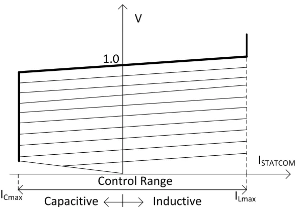
Figure 1.5 Operating characteristic of STATCOM ... 11
Figure 2.1 Vector representation of three phase variable ... 19
Figure 2.2 Vector representation of three phase variable in stationary (abc) and rotating reference (dq) frame ... 20
Figure 2.3 Schematic diagram of STATCOM connected to Grid ... 21
Figure 2.4 Block diagram of basic Type I controller for STATCOM ... 23
Figure 2.5 Block diagram of phase locked loop (PLL) ... 24
Figure 2.6 VSI output voltage vector and PCC voltage in dq reference frame ... 26
Figure 2.7 Block diagram of inner loop current controller of STATCOM ... 28
Figure 2.8 Sinusoidal pulse width modulation (SPWM) technique for VSI [62] ... 29
Figure 2.9 DC link voltage controller ... 30
Figure 2.10 Block diagram of STATCOM voltage regulator ... 30
Figure 2.11 STATCOM connected to Y-Y coupling transformer ... 31
Figure 2.12 STATCOM connected to Y-∆ coupling transformer ... 31
Figure 2.13 Positive sequence phasor diagram of Y-∆ transformer ... 32
xiii
Figure 2.16 Extraction of positive and negative sequence components ... 37
Figure 2.17 Negative sequence phasor diagram of Y-∆ transformer ... 39
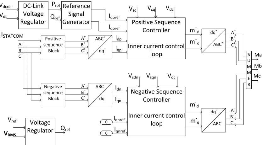
Figure 2.18 Block diagram of completer STATCOM controller for load compensation ... 41
Figure 2.19 Block diagram of completer STATCOM controller for voltage regulation ... 42
Figure 2.20 Block diagram of temporary overvoltage (TOV) regulator ... 43
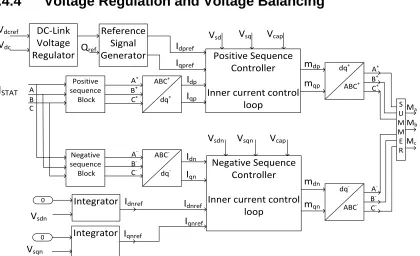
Figure 2.21 Block diagram of completer STATCOM control for voltage regulation and voltage balancing ... 43
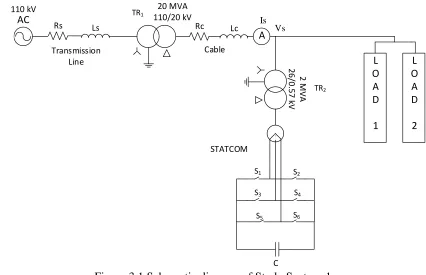
Figure 3.1 Schematic diagram of Study System-1... 46
Figure 3.2 (a) Simulation and (b) published results for compensation of unbalanced load for Study System-1 ... 48
Figure 3.3 Power factor during load compensation for Study System-1 ... 49
Figure 3.4 Positive and negative sequence currents in dq reference frame in (a) simulation and (b) published [10] results for load compensation for Study System-1... 51
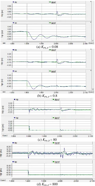
Figure 3.5 Positive sequence current (in dq frame) for different gain (Kpq_p) values ... 53
Figure 3.6 Positive sequence current (in dq frame) for different time constant (Tiq_p ) ... 54
Figure 3.7 Schematic diagram of Study System-2... 56
Figure 3.8 (a) PCC Voltage, (b) RMS voltage and (c) source current for steady state operation with Study System-2 ... 57
xiv
current for steady state operation with Study System-2 ... 60
Figure 3.11 (a) PCC Voltage, (b) power factor and (c) source current for Study System-2 without STATCOM ... 61
Figure 3.12 (a) PCC Voltage, (b) power factor and (c) source current for load compensation study for Study System-2 with STATCOM ... 62
Figure 3.13 (a) STATCOM current, (b) q-axis part of current, (c) reactive power output in dq frame, (d) d-axis part of current, (e) active power output in dq frame and (f) DC-link voltage for load compensation for Study System-2 ... 63
Figure 3.14 (a) d-axis and (b) q-axis parts of negative sequence component of STATCOM current for load compensation for Study System-2 ... 65
Figure 3.15 Schematic diagram of Study System-3 ... 66
Figure 3.16 (a) PCC Voltage, (b) power factor and (c) source current for study with gross unbalanced load without STATCOM ... 67
Figure 3.17 (a) PCC Voltage, (b) power factor and (c) source current for study with gross unbalanced load with STATCOM ... 68
Figure 3.18 (a) STATCOM current, (b) capacitor voltage, (c) and (d) active and reactive power output, respectively for gross unbalanced load with STATCOM... 69
Figure 3.19 (a) d-axis and (b) q-axis parts of negative sequence component of STATCOM current for gross unbalanced load ... 70
Figure 3.20 (a) PCC Voltage, (b) power factor and (c) source current for gross unbalanced load with Vdc = 1.4 kV ... 71
xv
current for gross unbalanced load with Vdc = 1.4 kV ... 73
Figure 3.23 Schematic diagram for Study Sytem-4 ... 74
Figure 3.24 a) PCC Voltage, (b) RMS voltage and (c) source current with Study System-4 for voltage balancing and regulation without STATCOM ... 75
Figure 3.25 (a) d-axis and (b) q-axis parts of negative sequence component of PCC voltage for voltage balancing and regulation without STATCOM ... 76
Figure 3.26 a) PCC Voltage, (b) RMS voltage and (c) source current with Study System-4 for voltage balancing and regulation with STATCOM ... 77
Figure 3.27 (a) STATCOM current (b) d-axis and (c) q-axis parts of negative sequence voltage at PCC and (d) reactive power output of STATCOM for voltage balancing and regulation with STATCOM ... 78
Figure 4.1 Single line representation of a realistic Hydro One feeder ... 81
Figure 4.2 (a) PCC voltage, (b) RMS voltage, (c) source and (d) load current and (e) load power factor for load compensation in realistic feeder without STATCOM ... 82
Figure 4.3 (a) PCC voltage, (b) RMS voltage, (c) source and (d) load current and (e) load power factor for load compensation in realistic feeder with STATCOM ... 84
Figure 4.4 (a) STATCOM current (b) and (c) positive sequence component of current in dq frame, (d) DC-link voltage, (e) and (f) STATCOM active and reactive power output for load compensation in realistic feeder... 85
Figure 4.5 (a) d-axis and (b) q-axis parameters of negative sequence component of
STATCOM current for load compensation in realistic feeder ... 86
xvi
power factor with grossly unbalanced load in realistic feeder without STATCOM operation ... 88
Figure 4.8 (a) PCC voltage, (b) RMS voltage, (c) source and (d) load current and (e) load power factor with grossly unbalanced load in realistic feeder with STATCOM operation ... 89
Figure 4.9 (a) STATCOM current (b) and (c) positive sequence component of current in dq frame, (d) DC-link voltage, (e) and (f) STATCOM active and reactive power output for grossly unbalanced load in realistic feeder ... 90
Figure 4.10 (a) d-axis and (b) q-axis parameters of negative sequence component of
STATCOM current for grossly unbalanced load in realistic feeder ... 91
Figure 4.11 Single line representation of feeder network with wind farm and night time load ... 92
Figure 4.12 (a) Wind farm terminal voltage and (b) reactive power supplied by STATCOM when 3 turbines operational ... 93
Figure 4.13 (a) STATCOM current (b) and (c) positive sequence d-axis and q-axis parts of current, (d) and (e) STATCOM active and reactive power output for voltage regulation in realistic feeder ... 94
Figure 4.14 (a) d-axis and (b) q-axis parts of negative sequence component of STATCOM current for voltage regulation in realistic feeder ... 95
Figure 4.15 (a) Wind farm terminal voltage and (b) reactive power supplied by STATCOM when 4 turbines operational ... 96
Figure 4.16 (a) Wind farm terminal voltage and (b) reactive power supplied by STATCOM when 5 turbines operational ... 97
xvii
without STATCOM when two wind turbines are operational ... 98
Figure 4.19 a) Three phase voltage at the wind farm terminal b) a magnified voltage plot with STATCOM when 2 wind turbines are operational ... 99
Figure 4.20 (a) STATCOM current (b) and (c) positive sequence component of current in dq frame, (d) and (e) STATCOM active and reactive power output for TOV regulation when 2 wind turbines are operational ... 100
Figure 4.21 (a) d-axis and (b) q-axis parts of negative sequence component of STATCOM current for TOV regulation when 2 wind turbines are operational ... 101
Figure 4.22 (a) Three phase voltage at the wind farm terminal (b) a magnified voltage plot without STATCOM when three wind turbines are operational ... 101
Figure 4.23 (a) Three phase voltage at the wind farm terminal (b) a magnified voltage plot with STATCOM (c) reactive power support of STATCOM when three wind turbines are operational... 102
Figure 5.1 Study System 1 for frequency scanning ... 105
Figure 5.2 Study System 2 with STATCOM ... 105
Figure 5.3 Positive sequence model of single cage induction generator ... 106
Figure 5.4 Positive sequence model of double cage induction generator ... 107
Figure 5.5 Equivalent ‘T’ model of transformer ... 107
Figure 5.6 IEEE (a) First and (b) Second SSR Benchmark line models ... 108
Figure 5.7 Study system 1 with IEEE (a) First SSR Benchmark and (b) Second SSR Benchmark line models... 109
xviii
[65] ... 110
Figure 5.10 Speed of wind farm for remote fault in (a) simulation and (b) published paper [54] ... 110
Figure 5.11 Effective resistances seen from the rotor for different sizes of single-cage induction generator based wind farms ... 114
Figure 5.12 Equivalent reactances seen from the rotor for different sizes of single-cage induction generator based wind farms connected to Study System 1 ... 116
Figure 5.13 Effective resistances seen from the rotor for different sizes of double-cage induction generator based wind farms ... 117
Figure 5.14 Equivalent reactances seen from the rotor for different sizes of double-cage induction generator based wind farms connected to Study System 1 ... 120
Figure 5.15 Equivalent reactance seen from the rotor for different sizes of double-cage induction generator based wind farms connected to Study System 1 ... 122
Figure 5.16 Comparison of the outcomes from eigenvalue analysis and frequency scanning analysis for 200 MW wind farm ... 124
Figure 5.17 System parameters for 40% series compensated line with remote fault ... 126
Figure 5.18 System parameters for 50% series compensated line with remote fault ... 128
Figure 5.19 System parameters for 60% series compensated line with remote fault ... 129
Figure 5.20 System parameters for 40% series compensated line with close-in fault ... 131
Figure 5.21 System parameters for 50% series compensated line with close-in fault ... 132
Figure 5.22 System parameters for 60% series compensated line with close-in fault ... 133
xix
series compensation ... 136
Figure 5.25 Speed of generator for different fault duration ... 137
Figure 5.26 Generator speed and terminal voltage for 100 MW wind farm with and without STATCOM ... 138
Figure 5.27 a) Generator speed and b) terminal voltage for 200 MW wind farm with and without STATCOM ... 139
Figure 5.28 a) Generator speed and b) terminal voltage for 300 MW wind farm with and without STATCOM ... 140
Figure 5.29 (a) Generator speed and (b) RMS voltage at terminal in case of asymmetric fault without STATCOM ... 141
Figure 5.30 (a) Generator speed and (b) RMS voltage at terminal (c) d-axis and (d) q-axis parameters of negative sequence voltage at STATCOM e) STATCOM reactive power output without negative sequence voltage controller in case of asymmetric fault ... 142
xx
STATCOM : Static Synchronous Compensator
PSCAD : Power System Computer Aided Design
EMTDC : Electro-Magnetic Transient for DC
FACTS : Flexible AC Transmission Systems
SVC : Static VAR Compensator
SSR : Subsynchronous Resonance
VSI : Voltage Sourced Inverter
SPWM : Sinusoidal Pulse Width Modulation
TOV : Temporary Overvoltage
IEEE FBM : IEEE First SSR Benchmark Model
IEEE SBM : IEEE Second SSR Benchmark Model
IG : Induction Generator
DFIG : Doubly Fed Induction Motor
PCC : Point of Common Coupling
PLL : Phase Locked Loop
xxi
List of Appendices
xxii
Ia : Condenser’s armature current If : Field excitation current ISVC : Current output of SVC
ISTATCOM : Current output of STATCOM
ω : Synchronous rotating speed (377 rad/sec)
𝜃 : Instantaneous angle between the a-axis and d-axis
𝑅𝑆 : Inverter and transformer conduction losses
𝑅𝑝 : Power loss in the inverter switches and capacitor
𝐿𝑆 : Leakage reactance of transformer or smoothing reactor
e : VSI output voltage
VS : Three phase voltage at PCC VRMS : Three phase RMS voltage at PCC
𝑒𝑎, 𝑒𝑏, 𝑒𝑐 : Phase A, B and C voltage at VSI output terminal
𝑉𝑎, 𝑉𝑏, 𝑉𝑐 : Phase A, B and C voltage to neutral at PCC
𝐼𝑎, 𝐼𝑏, 𝐼𝑐 : Phase A, B and C current output of STATCOM
𝑒𝑑, 𝑒𝑞 : d-q axis voltage at VSI output terminal
𝑉𝑠𝑑, 𝑉𝑠𝑞 : d-q axis parts of positive sequence voltage at PCC
𝑉𝑠𝑑𝑛, 𝑉𝑠𝑞𝑛 : d-q axis parts of negative sequence voltage at PCC
𝐼𝑑𝑝, 𝐼𝑞𝑝 : d-q axis part of positive sequence STATCOM current
𝐼𝑑𝑛, 𝐼𝑞𝑛 : d-q axis part of negative sequence STATCOM current
𝐼𝑑𝑝𝑟𝑒𝑓, 𝐼𝑞𝑝𝑟𝑒𝑓 : Reference d-q axis part of positive sequence STATCOM current
𝐼𝑑𝑛𝑟𝑒𝑓, 𝐼𝑞𝑛𝑟𝑒𝑓 : Reference d-q axis part of negative sequence STATCOM current P, Q : Active and Reactive power output of STATCOM
xxiii 𝑉𝑑𝑐
𝑚𝑎, 𝑚𝑏, 𝑚𝑐 : Modulation indices for A, B and C phase leg of Inverter
𝑚𝑑, 𝑚𝑞 : Modulation indices in dq reference frame
ϒ : Angle difference between VSI voltage vector and PCC voltage vector
IS , ILoad : Three phase source and load current
Kpd_p , Tid_p : Gain and time constant of active power controller Kpq_p , Tiq_p : Gain and time constant of reactive power controller
Kpd_n , Tid_n : Gain and time constant of negative sequence d-axis current controller Kpq_n , Tiq_n : Gain and time constant of negative sequence q-axis current controller Kpdc , Tidc : Gain and time constant of DC-link voltage controller
s : Slip of the generator
𝐿𝑡 : Leakage inductance of interconnecting transformer
𝑅𝑟, 𝑋𝑟 : Rotor winding resistance and leakage reactance per phase
𝑅𝑠𝑡, 𝑋𝑠𝑡 : Stator winding resistance and leakage reactance per phase
𝑋𝑚 : Magnetizing leakage reactance per phase
𝐶𝑔 : Capacitance of wind turbine generator terminal capacitor
RLine, XLine : Line resistance and reactance for IEEE FBM C : Capacitance for series compensation in line
VS : Three phase RMS voltage at wind farm terminal
w : Speed of wind turbine
𝑓𝑒𝑟 : Electrical resonant frequency
𝑇𝑒𝑚𝑡 : Electromagnetic torque output of generator
Chapter 1
INTRODUCTION
Load compensation, voltage balancing and voltage regulation are some of the major problems being faced by electric power utilities across the globe. If not addressed, these issues can cause power losses in lines, mal-operation of critical loads, damage to customer equipment, and potentially power system instability. Dynamic reactive power compensation is typically required to solve the above problems. Static Synchronous Compensator (STATCOM) is a rapidly acting high power electronic dynamic reactive power compensator which is increasingly being employed worldwide for the above purposes. This chapter presents a description and literature review of each of the above problems and the different methods, including STATCOM, which are used in power industry to solve these issues. While STATCOM controllers have been developed for addressing either one or two of the above problems, the motivation for developing a new STATCOM controller for comprehensively addressing all the three problems, is presented. Finally, the outline of each of the chapters of this thesis is described.
1.1
LOAD COMPENSATION
Loads in electric power systems are both static and dynamic [1], [2]. In addition, these loads can be balanced, such as motors or unbalanced, such as single phase loads [3], [4], arc furnaces [5], or traction loads [6], [7]. The loads are typically resistive-inductive in nature. A higher inductive component results in poor power factor which causes utilities to send more current in their distribution lines to serve the same real power load. The utilities have to incur more line losses while receiving the same revenue [8]. Penal tariffs are imposed by utilities to enforce customers to regulate their power factor above utility acceptable norms, typically 0.9 [9].
and subways. Due to DC drives, utilities are vulnerable to unbalanced load and poor power factor. One of these issues has been reported with Wellington’s cable car in New Zealand [6].
The problem of poor power factor, voltage flicker and load unbalance is not limited to public areas but it affects the industrial sector also mainly steel industries and other metallurgical industries [6]. The latest problem has been reported in Vyksa metallurgical plant in Russia and with a steel manufacturing unit in Mississippi, USA [6]. These units use arc furnaces for their operation, which causes unbalanced load on three phase network. Due to this, voltage sensitive loads such as hospitals and surrounding utility distribution networks face problem in their regular operation [3], [6].
The development of train traffic and growth of high speed trains [7] resulted into power quality deterioration as reported by the French rail system operating between Paris and Rennes in Western France, fed from the RTE national power grid [6]. These single phase traction loads were connected with three phase power transmission and sub-transmission grid. Operation of these heavy and strongly time varying traction loads causes voltage unbalance in phases of the grid. If it had not been remedied, poor power quality would have spread throughout the grid and caused complications for other customers taking power from the same grid. Due to grid code which requires power quality at PCC (point of common coupling) within specified limits, utilities may not permit rail traffic on the lines [6].
1.2
VOLTAGE UNBALANCE
This problem relates to the unbalance not in the loads but in the transmission network which feeds the loads [3]. Transmission and distribution lines supply power from the generating stations to the end loads of customers. A network unbalance may be caused by unequal inductances/impedances in each of the three phases of the lines. Lines have both self and mutual inductances. While self-inductances are generally equal in the three phases over the same length of the line, mutual inductance between the conductors depends on distance between conductors. All conductors, by the nature of design of transmission towers, cannot be placed symmetrically which results in unequal mutual inductances between the phases [12]. Generally many transmission lines have horizontal configuration due to simplified construction of the tower, which is also economical. Lines having asymmetrical conductor spacing experience different inductances in the three phases [12]. Hence, voltages become unbalanced and negative sequence voltages appear on transmission line. This can potentially lead to mal-operation of utility and customer equipment [13]. Transposition of the lines is therefore carried out to reflect equal mutual inductance between three phase conductors [8].
In New Zealand the 220 kV transmission lines are not transposed, resulting in voltage unbalance in the grid. The unbalance worsens as the load increases [13]. An Australian utility with a 500 kV transmission network has also experienced sequential tripping of generators due to excessive negative sequence voltage, causing a total blackout [14]. Unbalanced voltage has also been observed with distribution feeders [15] as it also has untransposed distribution lines and single phase lines.
1.3
VOLTAGE REGULATION PROBLEM
All power system equipment at generation, transmission or distribution ends require appropriate voltage magnitude to function effectively [1]. This issue of voltage regulation relates to the magnitude of voltages in three phase balanced systems, and not the unbalanced networks described in Section 1.2. Voltage regulation is of critical importance in power system. Lack of voltage control can even lead to power system instability [1], [17].
In mining, metallurgical and petro-chemical industries [18], three phase induction motors (dynamic load) are used for transportation. Induction motors are very sensitive to voltage [19]. If voltage goes low, motors consume more reactive power, which further lowers the voltage. This cyclic phenomenon potentially results in voltage collapse on the feeder line [1]. In British Columbia, due to expansion of oil pipe lines, three additional pumping stations were built. These pumping stations with high power motors created significant load change on the radial line to which they were connected, resulting in voltage instability [6].
A rolling mill is a large and unpremeditated consumer of electric power. It generates harmonics and fluctuations into the surrounding power network [6], [10]. In the event of a weak grid, large motor drives of a rolling mill can even trip out on low voltage since the startup of the mill drive can cause voltage dips of more than 10%. This may stall production and damage the plant economy as reported by Aktogay sulphide plant in Kazakhstan [6]. Lack of voltage regulation may also impede regular operation of other voltage sensitive loads such as medical services, electronic data centers etc [20], [21].
1.3.1
Voltage Control to Increase Connectivity of Wind Farms
wind power that can be sent over the lines. Voltage control mechanisms are therefore installed in several utilities [23] to allow a higher connectivity of wind farms.
1.3.2
Voltage Control to Prevent Subsynchronous Resonance
(SSR) in Series Compensated Wind Farms
There is growing need worldwide to increase the power transfer capacity of transmission lines to carry additional amounts of power coming from various generating sources - largely wind farms. Series compensation is employed in transmission lines to increase the stable capacity of transmission corridors without needing to construct new transmission lines at enormously high costs.
Due to the rapid growth of wind power system in the energy market, the large wind farms are being integrated with electrical networks that are series compensated [25] - [28]. Series compensation, although increases the power transfer capability of existing transmission lines, may potentially cause SSR in wind turbine generators [25], [26]. Recently, a case of subsynchronous resonance has been reported by Electric Reliability Council of Texas (ERCOT) in 2009 which occurred in a doubly-fed induction generator (DFIG) based wind farm [29]. Substantial damages to wind turbines were caused due to this event. Therefore, it is necessary to study the potential for subsynchronous resonance before planning the interconnection of wind farms to series compensated transmission lines.
1.4
CONVENTIONAL REACTIVE POWER
COMPENSATION METHODS
1.4.1 Synchronous Condenser
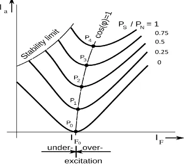
A synchronous condenser is a synchronous motor operating at no load. The synchronous condenser can supply variable reactive power for voltage regulation and power factor correction through appropriate control of field current of the motor. Figure 1.1 presents the condenser’s armature current Iawith respect to field excitation current If.
Figure 1.1 Synchronous condenser’s armature current and field current relationship This device can either work in inductive or capacitive mode depending upon field current excitation in rotor winding. With respect to different field currents, it supplies varying armature current Ia which is 90° out of phase with voltage, thereby transfering only reactive power [30].
F F0
0.25 0.5 0.75
a
support. Due to large inertia of the rotating mechanical part (rotor), it has slow speed of response (large time constant) and takes 300-500 ms for dynamic reactive power compensation [12]. The synchronous condenser requires no physical inductor or capacitor and does not generate harmonics. Synchronous condensers still exist and are being installed around the world.
1.4.2
Static VAR Compensator (SVC)
With the development of power electronics, Flexible AC Transmission System (FACTS) devices like SVCs have been used for dynamic reactive power compensation [1], [6], [17]. These devices are static in nature and do not have any rotating parts like synchronous condenser. Due to being static in nature and with the use of power electronic switches, SVC gives faster response than synchronous condenser.
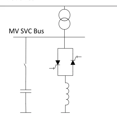
A typical SVC is given in Figure 1.2. It consists of a capacitor connected with a mechanical switch and an inductor in series with antiparallel connected thyristor switches. The unit is connected to high voltage (HV) line with a transformer in order to lower the voltage rating of thyristor valves [1].
Figure 1.2 Static VAR compensator HV SVC Bus
To supply reactive power, capacitor is connected with the grid; and for dynamic support thyristors valves are operated to provide variable inductive power. Thus with combined operation SVC works as a variable capacitor or a variable inductor.
A typical V-I characteristic of SVC is given in Figure 1.3. It presents the reactive current ISVC support by SVC for different voltages V . In capacitive and inductive operating region, SVC maintains the voltage profile at the PCC with a slope. Slope is added to SVC to make use of smaller rated SVC for large voltage fluctuation. The firing angle is controlled from β = 900 to 1800. At β = 1800, it reaches its limit on capacitive power ‘Production limit’, thus thyristors are blocked and only the capacitor supplies reactive power. Hence, SVC performance degrades with lower voltage. In a similar manner, thyristors are bypassed after reaching β = 90° and SVC works on ‘absorption limit’ with full inductor connected in shunt [1], [17].
Control Range Capacitive Inductive Production limit
BSVC = BC
β = 180°
β
=
9
0
°
V
ISVC
Absorption limit BSVC = BC + BL
β = 90°
β
=
1
8
0
°
Figure 1.3 Operating characteristic of SVC
installed at Laurentides substation.
SVC has also been used with arc furnaces for load compensation and with single phase traction loads for negative sequence voltage control [3], [5], [17]. Other FACTS devices that have similar configuration to SVC are TSC, FC-TCR, MSC-TSC [1]. All these FACTS devices use thyristors and physical inductors and capacitors for reactive power compensation.
1.5
STATIC SYNCHRONOUS COMPENSATOR
(STATCOM)
STATCOM is an advanced FACTS device that uses no physical inductor or capacitor for reactive power support unlike SVC. STATCOM supplies reactive power by exchanging the instantaneous reactive power among phases of the AC system.
1.5.1
Configuration
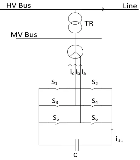
STATCOM uses IGBT, IGCT or GTO as switching devices. In these switches, both switching ON and switching OFF events can be controlled. So this gives two degrees of freedom compared to one degree of freedom given by thyristors in SVCs. This makes it faster and more effectively controllable. Figure 1.4 presents a typical STATCOM connected to a medium voltage (MV) bus. A transformer ‘TR’ is used to lower down the voltage from high voltage (HV) bus so that lower voltage rating switches (S1-S6) can be utilized. It has a capacitor at dc-link to provide the path for current [1].
Figure 1.4 Static synchronous compensator (STATCOM)
1.5.2
Operating Characteristics
V-I characteristics of STATCOM is presented in Figure 1.5. STATCOM reactive power output does not depend on voltage at the bus. So even in case of very low bus voltage, STATCOM can work with its full capacity unlike SVC whose performance degrades with lower bus voltage (Figure 1.3). STATCOM is preferred over SVC at locations where voltage goes too low or drops down very fast, so instant control is required [1].
For unbalanced voltage control by SVCs a 3rd harmonic filter is required. It occupies a large area. Hence it is generally avoided by utilities. Whereas, STATCOM does not have any low order filter requirements and hence is a preferred solution for mitigating unbalance. Superiority of STATCOM over SVC is presented in [5].
C
`
ia ib ic HV Bus
MV Bus
Line
idc
S1 S2
S3
S5
S4
Figure 1.5 Operating characteristic of STATCOM
1.5.3
Application of STATCOM
The main application of STATCOM is to provide dynamic reactive power compensation and to regulate the voltage at the interconnecting bus within acceptable limits.
There are several jurisdictions in Canada that use STATCOM. Mining and metallurgical industries have installed STATCOM to strengthen their electrical supply [20]. Petro chemical industries use high power motors, because of which voltage goes down on the feeder [18]. To maintain the reliability of power and provide fast dynamic voltage support during balanced and unbalanced fault conditions, the utility has installed three units of 12 MVAr STATCOM in British Columbia [6].
Gold mine facilities in Ontario have used the STATCOM solution to assist their high power demand or increased load due to expansion of existing mining facility [6]. A new mining development in Ontario requires high power electrical machines fed over very long cable lengths. To assist their operation, they have used 6 units of STATCOM, each rated 4.5 MVAr for reactive power support to regulate voltage [6]. The fast response time of STATCOM ensures power performance requirement, with longevity of motors and process equipments, thus assuring fast return on investment [6].
Control Range
Capacitive Inductive
V
ISTATCOM
ILmax
ICmax
Induction motors at mine loads are major cause of voltage collapse and poor power quality [19]. Saskatchewan has high concentration of induction motors at the mine loads [6]. With increase in load, facilities become vulnerable to equipment inefficiencies and tripping offline due to poor voltage at bus. A utility has employed two 5.5 MVAr STATCOM for dynamic VAr compensation to mitigate the network impact [6].
1.6
CONTROL STRATEGIES FOR STATCOM
STATCOM consists of a Voltage Sourced Inverter (VSI) without any DC voltage source at dc-link. There are different inverter configurations available for STATCOM such as multi-level inverter [15], modular multi-level inverter [20], six-pulse three phase inverter [1], [6], cascaded converter based STATCOM [4], cascaded H-bridge converter with star configuration [2], [31], three level neutral point clamped (NPC) inverter [32] etc. For the purpose of load compensation and voltage balancing a six-pulse inverter configuration is selected due to .
There are various modulation strategies in literature for inverters such as symmetrical multiple pulse modulation, sinusoidal pulse width modulation (SPWM), selective harmonic elimination pulse width modulation (SHEPWM) [33], [40] etc. No control over harmonics is present in symmetrical multiple pulse modulation technique. Lower order harmonics can be successfully removed with SHEPWM. However, probability of derating of converter is higher. Therefore, SPWM technique is used to keep harmonics under the limit specified by IEEE Standard 519 [34] by employing appropriate switching frequency [32].
suggested instead of Clark transformation (abc to dq) in [11]. Large power systems are generally analyzed in dq frame [37]. Also, achieving zero steady state error is simpler in dq reference frame control as compared to αβ frame control. Therefore, representation and control of STATCOM in dq frame is employed in [32], [38]. In this thesis, control is executed with SPWM technique in synchronous rotating (dq) reference frame that allows decoupled and fast control of active power and reactive power.
Being an expensive device, STATCOMs are typically installed for fast voltage regulation or power factor correction in networks where voltage excursion is large [1]. There is a trend in recent years to add more features in STATCOM to increase its versatility for various purposes and with other power sources like with petroleum industries and high speed railway [7], [18] and [39]. Following this, a co-ordination of STATCOM with other power sources is addressed in [39]. In case of unbalanced load, negative sequence current flows through compensator and introduces 2nd harmonic voltage component on DC-link. If not amended, it will cause 3rd harmonic current component on the AC side thus, deteriorating the STATCOM performance [10]. Furthermore, a severe imbalance may cause large negative sequence current on AC side forcing STATCOM to go offline and restricting its reactive power support.
modelling is carried out to get instantaneous values for feed-forward decoupling. Nevertheless, settling time of STATCOM is illustrated to be 4-5 cycles in [10].
In [2], [43], [44] in case of unbalanced voltages different techniques to limit the negative sequence current by STATCOM is discussed, however these do not discuss the mitigation of negative sequence voltage. For voltage balancing STATCOM having a Type II control [38] with SPWM has been discussed in [15], [45]. A large capacitor is suggested in [15] to reduce the ripple in DC-link capacitor voltage. To overcome this problem, an inner current control loop is cascaded with voltage balance controller in [45] to enable inverter over-current protection in a 3-phase 4-wire STATCOM. The response time with such over-current control loop has been reported to be 300 ms.
It is thus seen that different STATCOM controls have been proposed in literature for achieving either load compensation, voltage balancing or voltage control, individually, or in a combination of two functions. No controller seems to have been developed which can address the three issues simultaneously.
1.7
SSR WITH WIND FARM
There are two aspects of SSR: i) Self-excitation involving both induction generator effect and torsional interaction, and ii) Transient torque (also called transient SSR). Several techniques are available for the study of subsynchronous resonance in power systems. The most common techniques are: (i) Frequency scanning, (ii) Eigenvalue analysis, and (iii) Electromagnetic transient simulation [46], [47].
(DFIG), and the most recent trend is to use full converter based wind turbine generators [50]-[53]. However, there are large number of wind farms across USA, India, and Australia, etc., which utilize fixed speed induction generator (IG) based wind turbines [51]-[53].
In [54] a detailed analysis of SSR in wind farm is reported, in which comprehensive eigenvalues analyses are carried out followed by electromagnetic transient simulations. Authors in [55] presented some results of frequency scanning technique to investigate the sub-synchronous control interaction in wind farm, however, only IEEE Second SSR Benchmark System is considered with Type-3 wind farm. No frequency scanning studies have been reported with the more commonly referred IEEE First SSR Benchmark system, and also for induction generator based Type 1 wind farms.
1.8
MOTIVATION AND OBJECTIVE OF THESIS
Various control strategies for load compensation, voltage regulation and voltage balancing are available in literature with different configurations of STATCOM as reported in section 1.6. However, a comprehensive STATCOM controller in synchronous rotating reference frame with a six-pulse inverter configuration for all three tasks has not been discussed in literature so far. Hence, a composite controller for achieving all the three objectives needs to be designed in dq reference frame. Based on system requirements the required controller function may be activated. The developed STATCOM controller needs to be first validated from published results and a further effort needs to be made to accomplish faster response than STATCOM controllers reported in literature.
controller in increasing the wind farm connectivity in a realistic feeder based on both steady state voltage and Temporary Overvoltage (TOV) considerations will be demonstrated.
Frequency scanning technique is a fundamental technique for preliminary analysis of subsynchronous resonance. It is an approximate tool but has been proven as an efficient and cost effective method for analysis of subsynchronous resonance. Eigenvalue analysis and EMTP analysis give accurate results but are very time consuming. Therefore, a comprehensive frequency scanning analysis is presented to rapidly detect the potential for SSR in Type I induction generator based wind farms. The analysis is carried out considering both single-cage and double-cage induction generators. Frequency scanning analysis is performed with IEEE First and Second SSR Benchmark Systems [57], [58].
The impact of unsymmetrical faults and step change in series compensation levels on the behavior of wind farms connected to series compensated lines has not been reported before. This study has been undertaken in this thesis.
1.9
OUTLINE OF THESIS
A chapter-wise summary of this thesis is given below:
Chapter 2 explains the mathematical modelling of STATCOM controller for load compensation, voltage regulation and voltage balancing. Modifications in the controller for different configurations of coupling transformer are also explained. In addition, a controller is presented to bring down the TOV in phases of the line during asymmetrical faults.
feeder of Hydro One is presented in Chapter 4. To increase wind farm penetration with STATCOM, studies on the feeder of Hydro One are also carried out in the same. The STATCOM is used to limit over voltage at the wind farm terminal, arising due to SLG fault. The ability of STATCOM to alleviate this problem is presented in this chapter.
Chapter 5 presents the frequency scanning studies for SSR with single-cage wind farm and double cage wind farm connected with IEEE First SSR Benchmark Model and IEEE Second SSR Benchmark Model. Validation of results with eigenvalue analysis are also presented in the chapter. The effectiveness of the STATCOM is demonstrated for alleviating SSR in the series compensated transmission system. The impact of changes in compensation level, size of wind farms, location and intensity of fault and performance of comprehensive controller in case of asymmetric faults is discussed in this chapter.
Chapter 2
STATCOM CONTROLLER DESIGN FOR BALANCED AND
UNBALANCED NETWORK
2.1
INTRODUCTION
In this chapter, a detailed modeling of STATCOM controller is presented for balanced and unbalanced electrical system. In balanced electrical system, primary STATCOM controller consists of an inner current control loop and outer control loop. Positive sequence controller design for inner current control loop is explained in synchronous rotating reference (dq) frame. Outer control loop for DC-link voltage control, power factor correction and voltage regulation are also discussed. Furthermore, the controller is modified to include the effect of different configurations of coupling transformer.
For STATCOM operation in unbalanced electrical system, a negative sequence controller is developed that uses Fortescue decomposition technique to obtain sequence components. Separation of positive and negative sequence components is presented without using a 2nd harmonic notch filter. Subsequently, the transformation of sequence components to their respective rotating reference (dq) frame is described for utilization into negative sequence current control loop.
Successively, a supplementary controller is developed for load compensation, which includes power factor correction and compensation of negative sequence load current. A temporary overvoltage (TOV) regulator is also developed to regulate the overvoltage in case of asymmetric faults. A voltage balancing controller, together with voltage regulator is designed and block diagrams of complete controllers are also presented.
2.2
STATCOM CONTROL IN BALANCED NETWORK
active and reactive power flowing through STATCOM by utilizing dq-axis parameters [38]. In dq axis rotating reference frame, the three phase AC quantities become DC in nature. It is easier to apply control techniques on DC values compared to three phase AC quantities that change with time [32].
2.2.1
abc
to
dq
Frame Transformation
The three phase electrical variables i.e. voltage, current or flux linkage can be represented by a vector. The vector representation of instantaneous three phase variables in abc stationary reference frame is presented in Figure 2.1 [38], [59].
+ B phase axis
+ C phase axis
+ A phase axis
f
→f
af
cf
b ωtω
Figure 2.1 Vector representation of three phase electrical variable
Space vector 𝑓⃗ is given by
𝑓⃗(𝑡) = 2
3(
𝑓
𝑎(𝑡) +𝑓
𝑏(𝑡)𝑒𝑗2𝜋 3 +
𝑓
𝑐(𝑡)𝑒−𝑗
2𝜋
3) (2.1)
where 𝑓𝑎(𝑡), 𝑓𝑏(𝑡) and 𝑓𝑐(𝑡) are given as
𝑓𝑏(𝑡) = 𝐴 cos (𝜔𝑡 − 2𝜋 3 )
𝑓𝑐(𝑡) = 𝐴 cos (𝜔𝑡 − 4𝜋
3) (2.2)
where, ‘A’ is the amplitude of each electrical phase vector and ‘𝜔’ is the synchronous rotating speed (377 rad/sec) of space vector. The space vector rotates with speed 𝜔 with respect to stationary reference frame. These three phase variables in abc stationary reference frame can be transformed into two phase variables in a rotating reference frame which consists of d- (direct) axis and q- (quadrature) axis. This dq frame rotates with the same speed 𝜔 of space vector. Transformation is done as follows [60]:
[𝑓𝑓𝑑
𝑞] =
2 3[
cos (𝜔𝑡) cos (𝜔𝑡 −2𝜋
3 ) cos (𝜔𝑡 + 2𝜋
3 ) −sin (𝜔𝑡) −sin (𝜔𝑡 −2𝜋
3 ) −sin (𝜔𝑡 + 2𝜋 3) ] [ 𝑓𝑎(𝑡) 𝑓𝑏(𝑡) 𝑓𝑐(𝑡)
] (2.3)
where, 𝑓𝑑 and 𝑓𝑞 are the component of space vector along d-axis and q-axis respectively.
+ B phase
axis
+ C phase
axis
+ A phase
axis
f
→f
af
cf
b ωtω
ω
d - axis
q - axis
θ
f
df
qBecause of the transformation, 𝑓𝑑 and 𝑓𝑞 are DC quantities. Hence, the space vector 𝑓⃗(𝑡) can be expressed as
𝑓⃗(𝑡) = (𝑓𝑑+ 𝑗𝑓𝑞) 𝑒𝑗𝜔𝑡
Figure 2.2 presents the space vector 𝑓⃗(𝑡) both in stationary reference frame (abc) and rotating reference frame (dq). 𝜃 is the instantaneous angle between the a-axis and d-axis. The dq reference frame rotates in space with speed 𝜔 = dθdt
2.2.2
Modeling of STATCOM connected to a grid
Grid
LLine
STATCOM
C
L
O
A
D
RLine Vs
Transmission Line
S1 S2
S3 S4
S5 S6
LS RS
e
Ia Ib Ic
Rp
Figure 2.3 Schematic diagram of STATCOM connected to Grid
losses in the inverter and power loss in capacitor, 𝑅𝑆 represents inverter and transformer conduction losses and 𝐿𝑆 is the leakage reactance of transformer or smoothing reactor or a combination of both. 𝐼𝑎, 𝐼𝑏and 𝐼𝑐 are the phase currents flowing out of STATCOM in the Figure 2.3. PCC voltage and VSI output voltage are denoted by ‘VS’ and ‘e’ respectively.
The output phase voltages of VSI are given by 𝑒𝑎, 𝑒𝑏 and 𝑒𝑐 . The phase voltages at the PCC are denoted as 𝑉𝑎, 𝑉𝑏 and 𝑉𝑐 . Then:
𝑒𝑎− 𝑉𝑎 = 𝑅𝑠𝐼𝑎+ 𝐿𝑠𝑑𝐼𝑎 𝑑𝑡 𝑒𝑏− 𝑉𝑏 = 𝑅𝑠𝐼𝑏+ 𝐿𝑠𝑑𝐼𝑏 𝑑𝑡 𝑒𝑐 − 𝑉𝑐 = 𝑅𝑠𝐼𝑐 + 𝐿𝑠 𝑑𝐼𝑐
𝑑𝑡 (2.4)
Combining all three phases:
𝑝 [ 𝐼𝑎 𝐼𝑏 𝐼𝑐] = [ −𝑅𝑠
𝐿𝑠 0 0
0 −𝑅𝑠
𝐿𝑠 0
0 0 −𝑅𝑠
𝐿𝑠] [ 𝐼𝑎 𝐼𝑏 𝐼𝑐] + 1 𝐿𝑠[ 𝑒𝑎− 𝑉𝑎 𝑒𝑏− 𝑉𝑏
𝑒𝑐− 𝑉𝑐] (2.5)
where, 𝑝 is operator for 𝑑
𝑑𝑡
.
Applying transformation from abc reference frame tosynchronously rotating dq reference frame from (2.3) to (2.5):
𝐿𝑠 𝑑 𝑑𝑡[ 𝐼𝑑𝑝 𝐼𝑞𝑝] = [−𝐿−𝑅𝑠𝑠𝜔 −𝑅𝐿𝑠𝜔𝑠] [ 𝐼𝑑𝑝 𝐼𝑞𝑝] + [ 𝑒𝑑− 𝑉𝑠𝑑
𝑒𝑞− 𝑉𝑠𝑞] (2.6)
Subscript ‘d’ and ‘q’ indicate electrical quantities in d-axis and q-axis reference frame respectively.
There are two basic type of voltage source inverters [38]: 1) Inverter Type I
control. With this type of inverter, capacitor voltage can be kept sufficiently high for independent control of 𝐼𝑑𝑝 and 𝐼𝑞𝑝 in (2.6). Inverter Type II is primarily used with transmission lines and have limited decoupled control on power flow [38]. Therefore, in this thesis control strategy of Type I inverter is utilized to meet the stated objectives.
2.2.3
Basic STATCOM Type
I
Controller
Figure 2.4 depicts the block diagram of basic Type I controller for STATCOM. In this figure, ‘DC-link voltage regulator’ is used to keep the constant capacitor voltage. ‘Reference signal generator’ block supplies reference current values needs to be supplied by STATCOM in dq frame. ‘PLL’ block takes PCC voltage VS as input and generate signal ‘𝜔t’ which is synchronized with phase ‘A’ of the VS . Simultaneously, STATCOM current ISTATCOM is transformed to dq reference frame and is given to ‘positive sequence controller’ block as feedback signal. This controller generates modulating signals in dq frame which are transformed to stationary abc frame and are forwarded to designated switching leg of inverter. Equations for abc to dq block are given in (2.3). The detailed description of other blocks is discussed below.
A B C abc dq Idp Iqp ISTATCOM Positive Sequence Controller
Inner current control loop
md
mq
Vdc
Vsd Vsq
Idpref Iqpref Reference Signal Generator DC-Link Voltage Regulator Qref Vdcref Vdc dq abc ωt ma mb mc ωt Pref PLL A B C
VS Vsd
Vsq
Figure 2.4 Block diagram of basic Type I controller for STATCOM
2.2.4
Phase Locked Loop (PLL) Design
reference frame with the phase A. The PCC voltage vector, therefore makes 𝜃 = 0° (Figure 2.2). Input signals to PLL are dq parts of PCC voltage. PI controller is used to obtain 𝑉𝑠𝑞= 0 and VCO outputs angle ‘𝜔t’. The output of PLL is the angle 𝜔t which is utilized to get dq frame transformation (2.3) of PCC voltage (𝑉𝑠𝑑 and 𝑉𝑠𝑞). 𝑉𝑠𝑑 attains the maximum phase voltage value as 𝑉𝑠𝑞 becomes zero.
PI
and
VCO
V
sdA
B
C
V
sqωt
abc
dq
d
q
Figure 2.5 Block diagram of phase locked loop (PLL)
2.2.5
Control of Real and Reactive Power Output from VSI
VSI power output equations can be calculated in dq reference frame [38]. The real power (P) and reactive power (Q) in dq frame are expressed as:
𝑃 = 3
2(𝑉𝑠𝑑𝐼𝑑𝑝+ 𝑉𝑠𝑞𝐼𝑞𝑝)
𝑄 = 3
2(𝑉𝑠𝑞𝐼𝑑𝑝− 𝑉𝑠𝑑𝐼𝑞𝑝)
(2.7)
Since, PLL calculates 𝑉𝑠𝑞 = 0, (2.7) can be rewritten as
𝑃 = 3
2(𝑉𝑠𝑑𝐼𝑑𝑝)
𝑄 = 3
2(−𝑉𝑠𝑑𝐼𝑞𝑝)
(2.8)
𝐼𝑑𝑝𝑟𝑒𝑓 = 2 3𝑉𝑠𝑑𝑃𝑟𝑒𝑓
𝐼𝑞𝑝𝑟𝑒𝑓 = − 2
3𝑉𝑠𝑑𝑄𝑟𝑒𝑓 (2.9)
This equation explains the operation of ‘Reference Signal Generator’ block presented in Figure 2.4.
2.2.6
VSI Output Voltage Vector in Synchronous Rotating
Reference frame
Sinusoidal pulse width modulation (SPWM) technique is utilized for generating firing pulses for electrical switches (S1-S6). In this scheme, VSI output voltage in Figure 2.3 is given as:
𝑒𝑎 = 𝑚𝑎(𝑡)
𝑉𝑑𝑐 2
𝑒𝑏= 𝑚𝑏(𝑡) 𝑉𝑑𝑐
2 (2.10)
𝑒𝑐 = 𝑚𝑐(𝑡)
𝑉𝑑𝑐
2
where 𝑚𝑎, 𝑚𝑏, 𝑚𝑐 are the modulation indices of each leg of the inverter and 𝑣𝑑𝑐 is the voltage of DC link capacitor. For dynamics and control analysis purposes, high frequency components can be omitted [32]. Also filters and controllers exhibit low pass characteristics in closed loop system. Hence, the average value of output voltage is considered instead of instantaneous value [32]. Considering only fundamental component of switching pulses:
𝑚𝑎1 = 𝑘 sin(𝜔𝑡 +ϒ)
𝑚𝑏1 = 𝑘 sin(𝜔𝑡 +ϒ− 2𝜋 3⁄ ) (2.11)
𝑚𝑐1 = 𝑘 sin (𝜔𝑡 +ϒ+ 2𝜋 3⁄ )
[38], [32], [61]. ϒ is the angle by which the VSI voltage 𝑒⃗ leads the PCC voltage. Neglecting the voltage harmonics produced by VSI, fundamental output voltage will be
𝑒𝑎1 = 𝑚𝑎1(𝑡)
𝑉𝑑𝑐 2
𝑒𝑏1 = 𝑚𝑏1(𝑡) 𝑉𝑑𝑐
2 (2.12)
𝑒𝑐1 = 𝑚𝑐1(𝑡) 𝑉2𝑑𝑐
Applying abc to dq transformation from (2.3) to (2.12)
𝑒𝑑 =
𝑉𝑑𝑐
2 𝑚𝑑
𝑒𝑞 =
𝑉𝑑𝑐
2 𝑚𝑞 (2.13)
where 𝑚𝑑 and 𝑚𝑞 are modulation indices in dq reference frame. Hence, the VSI output voltage vector from (2.13) can be expressed as
𝑒⃗(𝑡) = (𝑒𝑑 + 𝑗𝑒𝑞) 𝑒𝑗𝜔𝑡
q-axis
d-axis
VS →
Vsd
e →
ed
eq
ϒ
Figure 2.6 VSI output voltage vector and PCC voltage in dq reference frame Figure 2.6 presents the VSI output voltage vector 𝑒⃗ in dq plane. 𝑉⃗⃗⃗⃗𝑠 represents the voltage vector of PCC. The angle ‘ϒ’ and magnitude difference of 𝑒⃗ and 𝑉⃗⃗⃗⃗𝑠 determine the active and reactive power exchange with STATCOM.
2.2.7
Inner Current Control Loop (VSI Current Control)
𝐿𝑠𝑑𝐼𝑑𝑝
𝑑𝑡 = −𝑅𝑠𝐼𝑑𝑝+ 𝐿𝑠𝜔𝐼𝑞𝑝+ 𝑉𝑑𝑐
2 𝑚𝑑− 𝑉𝑠𝑑
𝐿𝑠𝑑𝐼𝑞𝑝
𝑑𝑡 = −𝑅𝑠𝐼𝑞𝑝− 𝐿𝑠𝜔𝐼𝑑𝑝+ 𝑉𝑑𝑐
2 𝑚𝑞− 𝑉𝑠𝑞 (2.14)
To facilitate decoupled control of output power, the control of 𝐼𝑑𝑝 and 𝐼𝑞𝑝 should be decoupled. As per (2.14) 𝐼𝑑𝑝 and 𝐼𝑞𝑝 are state variables. Coupling is present in system due to presence of 𝐿𝑠𝜔 term. To decouple 𝐼𝑑𝑝 and 𝐼𝑞𝑝 we select 𝑚𝑑 and 𝑚𝑞 such that
𝑚𝑑 = 2
𝑉𝑑𝑐(𝑢𝑑 − 𝐿𝑠𝜔𝐼𝑞𝑝+ 𝑉𝑠𝑑)
𝑚𝑞 =
2
𝑉𝑑𝑐(𝑢𝑞+ 𝐿𝑠𝜔𝐼𝑑𝑝 + 𝑉𝑠𝑞) (2.15)
where, 𝑢𝑑 and 𝑢𝑞 are control inputs, terms 𝐿𝑠𝜔𝐼𝑞𝑝 and 𝐿𝑠𝜔𝐼𝑑𝑝 are decoupling feed forward input and 𝑉𝑠𝑑 and 𝑉𝑠𝑞 are added as given in (2.14). Substituting 𝑚𝑑 and 𝑚𝑞 to (2.14), it simplifies to
𝐿𝑠𝑑𝐼𝑑𝑝
𝑑𝑡 = −𝑅𝑠𝐼𝑑𝑝+ 𝑢𝑑
𝐿𝑠
𝑑𝐼𝑞𝑝
𝑑𝑡 = −𝑅𝑠𝐼𝑞𝑝+ 𝑢𝑞 (2.16)
+
-
P
I
Idpref Idp + -Iqpref Iqp
P
I
+ + + + + -Vsd G ________________ 1+sT G ________________ 1+sT
Lsω
Lsω
Iqp Idp N/D N/D Vdc 2 md mq Vdc 2 ud uq Vsq
Figure 2.7 Block diagram of inner loop current controller of STATCOM
2.2.8
SPWM Technique
Modulation indices (𝑚𝑎, 𝑚𝑏 and 𝑚𝑐) from Figure 2.4 are the three reference signals for SPWM technique. dq to abc transformation is carried out to get three phase modulation indices. The dq to abc transformation matrix can be generated by inverting the matrix given in (2.3):
[ 𝑚𝑎(𝑡) 𝑚𝑏(𝑡) 𝑚𝑐(𝑡) ] = [
cos (𝜔𝑡) −sin (𝜔𝑡)
cos (𝜔𝑡 −2𝜋
3) −sin (𝜔𝑡 − 2𝜋
3) cos (𝜔𝑡 +2𝜋
3) −sin (𝜔𝑡 + 2𝜋
3)] [𝑚𝑚𝑑
𝑞] (2.17)
+𝑉𝑑𝑐
2 appears at phase output and when it is lesser than triangular wave −𝑉𝑑𝑐
2 appears at
the phase voltage. Taking an average over carrier wave time period, the output voltage results into a sinusoidal output.
Modulating Signal Carrier wave
1
+Vdc
2
-Vdc
2
Figure 2.8 Sinusoidal pulse width modulation (SPWM) technique for VSI [62]
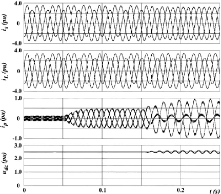
![Figure 3.4 Positive and negative sequence currents in dq reference frame in (a) simulation and (b) published [10] results for load compensation for Study System-1](https://thumb-us.123doks.com/thumbv2/123dok_us/7773855.1281137/75.612.117.535.72.327/positive-negative-sequence-currents-reference-simulation-published-compensation.webp)