Arc Truncated Suspended Rectangular
Microstrip Antenna
Suryakanth Nirate1, S.L.Mallikarjun2, R.M.Vani3, P.V.Hunagund4
Research Scholar, Dept. of Applied Electronics, Gulbarga University, Kalaburagi, Karnataka, India1 Guest Faculty, Dept. of Applied Electronics, Gulbarga University, Kalaburagi, Karnataka, India2 Professor & Head, Univ. Sci. Inst. Centre (USIC), Gulbarga University, Kalaburagi, Karnataka, India3 Professor & Chairman, Dept. of Applied Electronics, Gulbarga University, Kalaburagi, Karnataka, India4
ABSTRACT: In this paper design of Arc Truncated Suspended Rectangular Microstrip Antenna (ATSRMSA) is presented which operates for dual bands. The operating frequency range is from 3 GHz to 16 GHz. A low-cost glass epoxy substrate and is fed by a standard 50 Ω microstipline feed. The glass epoxy substrate with dielectric constant 4.4 is used for proposed design at resonant frequency of 8.91GHz. Radiation characteristics and return loss of the DBATSRMSA is measured by using Vector Network Analyser. The proposed antenna may find application in microwave communication systems operating in the frequency range of 3 to 16 GHz.
KEYWORDS: Microstrip Antenna, Arc Truncated antenna, Suspended, Rectangular, Glass epoxy Substrate.
I.INTRODUCTION
Microstrip patch antennas have a radiating patch, dielectric substrate and ground. Selecting substrate is a key step in designing because a property of an antenna varies with a different substrate materials. As we know that the demand of microstrip antenna is increasing day by day because of their large number of advantages such as low cost, low volume, easy integration and light weight etc. These advantages make microstrip antenna applicable for various applications such as mobile, radar, satellite communication field, etc [1-3].
Microstrip antennas are also relatively inexpensive to manufacture and design because of the simple 2-dimensional physical geometry. The other drawbacks of basic microstrip structures include low power handling capability, loss, half plane radiation and limitation on the maximum gain. Different techniques are used to overcome this narrow bandwidth limitation. These techniques include increasing the thickness of the dielectric substrate, decreasing dielectric constant and using parasitic patches [4]. However, research is still continuing today to overcome some of these disadvantages [5]. In this paper a design of Arc Truncated Suspended Rectangular Microstrip Antenna (ATSRMSA) is presented.
II.ANTENNA STRUCTURE
The ATSRMSA is designed for 6 GHz of frequency using the equations available for the design of conventional rectangular microstrip antenna in the literature [7]. The length and width of the rectangular patch are L and W respectively. The feed arrangement consists of quarter wave transformer of length Ltand width Wtwhich is connected
as a matching network between the patch and the microstripline feed of length Lf50 and width Wf50.Table.1 shows the
design parameters of the proposed antenna.
The art work of the proposed antenna is sketched by using computer software Auto-CAD 2006 to achieve better accuracy and is fabricated on low cost glass-epoxy substrate material of thickness ofh= 1.6 cm and permittivity
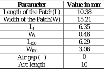
Table 1:Design Parameters of the Antenna
Parameter Value in mm
Length of the Patch(L) 10.38
Width of the Patch(W) 15.21
Lt 6.35
Wt 0.46
Lf50 6.29
Wf50 3.06
Air gap () 0
Arc length 10
Figure 1(b) shows the top view geometry of arc truncated suspended rectangular microstrip antenna (ATSRMSA). While truncating arc on the patch , antenna designed with air gap ()=0 mm [6] is considered. On the top of right side of the patch antenna, arc shape is incorporated. The fabricated antenna is tested using Vector Network Analyser ZVK series 1127.8651.60.
(a) Side view
(b) Top view
Air
Radiating Patch
SMA Probe
SMA Connector
Spacer
Ground Plane Copper Strip
Feed line
h
h
L
L
W
Wt
L
f5III.EXPERIMENTAL RESULTS AND DISCUSSION
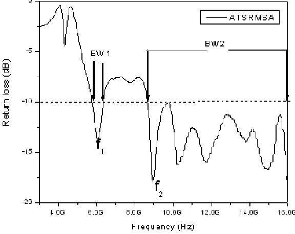
The antenna bandwidth over return loss less than -10 dB is measured experimentally on Vector Network Analyzer (Rohde & Schwarz, Germany make ZVK model 1127.8651.60). The variation of return loss verses frequency of ATSRMSA is as shown in Fig. 2. From this graph the experimental bandwidth (BW) is calculated using the equations
BW=[ (f2 - f1)/fc]×100% ... (1)
were, f1 and f2 are the lower and upper cut of frequencies of the band respectively when its return loss reaches – 10 dB
and fc is the center frequency of the operating band. i.e.
fc=[(f1+f2)/2] ... (2)
From this figure, it is clear that, the antenna operates between 3 GHz to 16 GHz and gives two resonant modes at f1 to
f2, i.e. at 5.76, and 8.86 GHz.
Fig. 2 Variation of Return loss Verses Frequency of ATSRMSA
Fig.2 shows the variation of return loss verses frequency of ATSRMSA. It is observed from the graph that the antenna operates for two bands of frequencies i.e, Band1 (BW1) and Band2 (BW2).
Table 2: Experimental results of ATSRMSA
Antenna name
Resonant Frequency
(GHz)
Return Loss (dB) Bandwidth (%)
Band1 Band2 BW1 BW2
Table 2 show the experimental results of ATSRMSA and it is observed that return loss of the Band2 is better compare
to Band1. Further antenna resonates at 8.91 GHz frequency
.
-12 -10 -8 -6 -4 -2 0 0 30 60 90 120 150 180 210 240 270 300 330 -12 -10 -8 -6 -4 -2 0 Co-Polar Cross-Polar
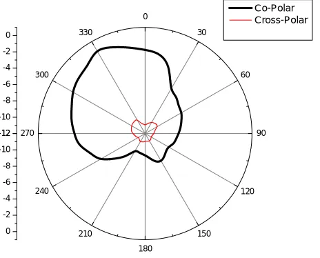
Fig.3 Radiation Pattern of Proposed DBATSRMSA
Fig.3 shows the radiation pattern of ATSRMSA. It is seen that antenna shows co-polarization and better minimum cross-polarization.
IV.CONCLUSION
In this paper design of Arc Truncated Suspended Rectangular Microstrip Antenna (ATSRMSA) is presented. From the detailed experimental study, it is concluded that, antenna operates for two bands of frequencies in the range of 3 GHz to 16 GHz. With these features the proposed antennas may find application in microwave communication systems operating in the frequency range of 3 to 16 GHz. Antenna gives better bandwidth of 9.7 and 59.65% respectively.
REFERENCES
[1] Md. Nazrul Islam, FarhanaYasmine, Sharif M. Ismail, and Md. TanvirHasan, “Wideband Rectangular Patch Antenna for Wireless Applications”, National Conference on Communication and Information Security (NCCIS 2009), Daffodil International University, Dhaka, Bangladesh, pp. 30-32, 14th February 2009.
[2] Kawei Qian and Xiaohong Tang, “Compact LTCC dual-band circularly polarized perturbed hexagonal microstrip antenna,” IEEE Antennas and Wireless Propagation Letters, Vol. 10, pp.1212-1215, 2011.
[3] K. Kumar and N. Gunasekaran, “A novel wideband slotted mm wave microstrip patch antenna,” Proc. IEEE Vol. 987-1, pp. 10-14, 2011. [4] S. I. Latif, Lotfollah Shafai and Satish Kumar Sharma, Member, IEEE, “ Bandwidth Enhancement and Size Reduction of Microstrip Slot
Antennas” , IEEE transactions on antennas and propagation,vol. 53, no. 3, march 2005.
[5] Vidya Deshmukh & Abhilasha Mishra, “Analysis & Designing Of E-Shape Microstrip Antenna With Slot For Ism Band”, International journal of research in engineering & technology (impact: ijret),issn(e): 2321-8843; issn(p): 2347-4599,vol. 2, issue 7, jul 2014, 41-48. [6] Suryakanth Nirate, S.L.Mallikarjun, R.M.Vani, P.V.Hunagund, “Wideband Microstrip-Line-Fed Suspended Rectangular Microstrip
Antenna”,IJAREEIE,vol. 4, issue 9, pp.7801-7805, september 2015.
[7] I. J. Bahl and P. Bharatia, “Microstrip Antennas”, Dedham,MA: Artech House, New Delhi, 1981.
[8] K.M.Luk, C.L. Mak, et al., “Broadband microstrip antenna,” Electronics letters, Vol.34, pp.1442-1443, 1998.
[9] P.H.Rao, V.Fusco and R. Cahill, “Wideband Linear and circularly polarized patch antenna using printed stepped T-feed.” IEEE Trans. Antennas and Propagation, Vol.Ap-50, pp.356-361, 2002.
[10] H.F.Pues and A.R.Van de Capelle, “An impedance matching technique for increasing the bandwidth of microstrip antennas,” IEEE Trans.Antennas and Propagation Vol.Ap-37, pp.1345-1354, 1989.
BIOGRAPHY
Mr. Suryakanth Nirate received his M.Sc. Applied Electronics degree from Gulbarga University, Kalaburagi in the year 2002 and completed M.Phil. Degree in the year 2007 from same Department. He is pursuing his Ph.D degree in Dept. of Applied Electronics, Gulbarga University, Kalaburagi in the field of Microwave Electronics. His areas of interest include Suspended Microstrip Antennas and Microstrip antennas.
Dr. S. L. Mallikarjun received his M.Sc., M.Phil. and Ph.D. degree in Applied Electronics from Gulbarga University, Kalaburagi in the year 2005, 2007 and 2011 respectively. He is working in Dept. of Applied Electronics, Gulbarga University, Kalaburagi. He has more than 80 publications in reputed International/National Journals and in conference and symposia. His Research interest includes microstrip antenna, arrays and dielectric resonator antenna.
Dr.Vani. R.M. received her B.E. in Electrical and Electronics from the B.I.ET., Davanagere, Karnataka, and M.Tech in Industrial Electronics from S.J.C.E., Mysore. She has received her Ph.D in Applied Electronics from Gulbarga University, Kalaburagi, in year 2005. She is working as Professor and Head, University Science Instrumentation Center, Kalaburagi, since 1995. She has more than 85 research publications in National and International reputed journals and Conference proceedings. She presented many research papers in India & Abroad. She has conducted several courses, workshops for the benefit of faculties and field engineers. Her areas of interest are microwave antennas, PC based Instrumentation, Embedded controllers and wireless communication. She has one UGC major research project to her credit.