ISSN (Print) : 2320 – 3765 ISSN (Online) : 2278 – 8875
I
nternational
J
ournal of
A
dvanced
R
esearch in
E
lectrical,
E
lectronics and
I
nstrumentation
E
ngineering
(An ISO 3297: 2007 Certified Organization)
Vol. 5, Issue 1, January 2016
Sensorless Vector Control of Induction Motor
Based On Extended Kalman Filter and Fuzzy
Controller
Bineet Kumar Khampariya, Manvendra Singh Kaurav
Research Scholar, Dept. of Electrical Engineering, LNCT, Bhopal, M.P, India
Assistant Professor, Dept. of Electrical Engineering, LNCT, Bhopal, M.P, India
ABSTRACT: This paper depicts the vector control of an induction motor by the speed estimation utilizing an extended Kalman filter and fuzzy controller. In this paper, the rotor speed is viewed as a parameter, and the composite state is made out of the first state and the rotor speed. The extended Kalman filter is utilized to distinguish the speed of an induction motor and rotor flux in light of the deliberate amounts, for example, stator currents and DC join voltage. The assessed speed is utilized for vector control and general speed control. The current control is performed at synchronous rotating reference frame, and the assessed speed data is utilized for reference frame transformation of the current controller. PC reproduction of the speed control has been completed to affirm the speed's helpfulness estimation calculation. The error between the genuine speed and the evaluated speed is inside of a couple rpm even at the low and high speeds.
KEYWORDS: Induction motor, Vector Control, Extended Kalman filter, Fuzzy logic controller.
I. INTRODUCTION
ISSN (Print) : 2320 – 3765 ISSN (Online) : 2278 – 8875
I
nternational
J
ournal of
A
dvanced
R
esearch in
E
lectrical,
E
lectronics and
I
nstrumentation
E
ngineering
(An ISO 3297: 2007 Certified Organization)
Vol. 5, Issue 1, January 2016
II. MATHEMATICAL MODEL OF INDUCTION MOTOR
As generally iron losses, saturation of the electromagnetic circuit are ignored when adding to the scientific model of the induction motor. A dynamical model of induction motor in a stationary reference frame, by picking the stator currents𝑖𝛼 ,𝑖𝛽and the rotor flux𝜓𝑟𝛼 , 𝜓𝑟𝛽 and the motor precise speed ω r as state variables is
𝑑𝑥
𝑑𝑡= 𝐴𝑥 𝑡 + 𝐵𝑢 𝑡 , … … … . . (1) 𝑦 𝑡 = 𝑐𝑥 𝑡 , … … … . (2)
Where𝑥 is the state vector.
𝑥 = 𝑖𝛼𝑠𝑖𝛽𝑠𝜓𝛼𝑟𝜓𝛽𝑟𝜔𝑟 𝑇
, … … … . . (3) 𝑦 = 𝑖𝛼𝑠𝑖𝛽𝑠𝑖𝑐𝑠
𝑇
, … … … . . (4) 𝑢 = 𝑣𝛼𝑠𝑣𝛽𝑠 , … … … . . (5)
𝐴 =
−𝜆 0 𝜏𝛼
𝑟
𝜔𝑟𝛼 0
0 −𝜆 −𝜔𝑟𝛼
𝛼 𝜏𝑟
0
𝐿𝑚 𝜏𝑟
0 −1
𝜏𝑟
−𝜔𝑟 0
0 𝐿𝑚
𝜏𝑟
𝜔𝑟
−1 𝜏𝑟
0
0 0 0 0 0
𝐵 = 1 𝜎𝐿𝑠
0
0 1
𝜎𝐿𝑠
0 0
0 0
0 0
Where
𝜆 = 𝑅𝑠 𝜎𝐿𝑠
+𝑅𝑟𝐿𝑚 2 𝜎𝐿𝑠𝐿2𝑟 𝑡𝑖𝑚𝑒 𝑐𝑜𝑛𝑠𝑡𝑎𝑛𝑡 = 𝜏𝑟 =
𝐿𝑟 𝑅𝑟 𝛼 = 𝐿𝑚
𝜎𝐿𝑠𝐿𝑟 𝜎 = 1 − 𝐿𝑚
2 𝐿𝑠𝐿𝑟 𝑅𝑠, 𝑅𝑟 : Stator and Rotor resistances.
𝐿𝑠, 𝐿𝑟 : Stator and Rotor self inductances.
ISSN (Print) : 2320 – 3765 ISSN (Online) : 2278 – 8875
I
nternational
J
ournal of
A
dvanced
R
esearch in
E
lectrical,
E
lectronics and
I
nstrumentation
E
ngineering
(An ISO 3297: 2007 Certified Organization)
Vol. 5, Issue 1, January 2016
𝑓𝑞𝑠𝑒 𝑓𝑑𝑠𝑒
= −sin(𝜔𝑒𝑡) 𝑐𝑜𝑠(𝜔𝑒𝑡) cos(𝜔𝑒𝑡) sin(𝜔𝑒𝑡)
2
3 −
1
3 −
1 3
0 1
3 1
3 𝑓𝑎𝑠 𝑓𝑏𝑠 𝑓𝑐𝑠 where𝑓 may represent either the voltage or current. 𝜔𝑒isthe synchronous speed.
𝜔𝑒 = 𝜔𝑠𝑙 + 𝜔𝑟, … … … . (6)
where𝜔𝑠𝑙is the slip speed and 𝜔𝑟 is the rotor speed. Thefield oriented control requires to keep the magnetizing current at a constant rated value by setting 𝑖𝑑𝑟𝑒 = 0 Hence thetorque producing current component can be adjusted inaccordance with the torque demand. The electromagnetictorque,
𝑇𝑒 = 3𝑃𝐿𝑚
4𝐿𝑟
𝜆𝑒𝑑𝑟𝑖𝑞𝑠𝑒 , … … … (7) where𝜆𝑑𝑟 is the 𝑑 axis rotor flux linkage.
III. EXTENDED KALMAN FILTER (EKF) ALGORITHM
In the dynamic model of induction motor, if the dimension of state vector is increased by adding an angular speed of rotor, then thestate model between nonlinear. So the extended Kalmanfilter has tobeused to estimate the parameter. In this case, the angular speedof the rotor is considered as a stateand a parameter. For the applicability of extended Kalman filter the system should be expressed in discrete state. Thediscrete state model and the output model are given by:
𝑋 𝑘 + 1 = 𝑓 𝑋 𝑘 , 𝑘 + 𝐺 𝑘 𝑤 𝑘 , … … … . . 8 𝑌 𝑘 = 𝐻 𝑘 𝑋 𝑘 + 𝑣 𝑘 , … … … (9) Where
𝐺 𝑘 =Weighting matrix.
𝑤 𝑡 =Noise matrix of state model. 𝑣 𝑡 =Nose matrix of output model.
In this model𝑓 𝑋 𝑘 , 𝑘 is the nonlinearpart of state model. The extended Kalman filter re-linearize the nonlinear state model about each new estimate as it becomes available, and the new discrete state model and output model isdescribed by Eq. (10),(11).
𝑋 𝑘 + 1 𝑘 + 1 = 𝐹 𝑘 𝑋 𝑘 + 1 𝑘 + 𝐺 𝑘 𝑤 𝑘 + 𝑠 𝑘 , … … … . . 10 𝑌 𝑘 = 𝐻 𝑘 𝑋 𝑘 𝑘 + 𝑣 𝑘 , … … … . (11)
Where
𝐹 𝑘 = 𝛿𝑓 𝑥 𝑘 , 𝑘
𝛿𝑘 𝑥=𝑥 𝑘+1 𝑘
𝑠 𝑘 = 𝑓 𝑥 𝑘 + 1 𝑘 − 𝐹 𝑘 𝑥(𝑘 + 1|𝑘)
From the above dynamic model therotor speed can be estimated by thefollowing extendedKalmanfilter algorithm. Estimation of error covariance matrix:
𝑃 𝑘 + 1 𝑘 =Φ 𝑘 + 1, 𝑘 𝑃 𝑘 𝑘 ΦT 𝑘 + 1, 𝑘 + 𝑄
𝑑 𝑘
Computation of Kalman filter gain:
𝐾 𝑘 + 1 = 𝑃 𝑘 + 1 𝑘 𝐻
𝑇 𝑘 + 1
𝐻 𝑘 + 1 𝑃 𝑘 + 1 𝐻𝑇 𝑘 + 1 + 𝑅 𝑘 + 1 Update for error covariance matrix:
𝑃 𝑘 + 1 𝑘 + 1 = 𝐼 − 𝐾 𝑘 + 1 𝐻 𝑘 + 1 𝑃(𝑘 + 1|𝑘) State estimation:
ISSN (Print) : 2320 – 3765 ISSN (Online) : 2278 – 8875
I
nternational
J
ournal of
A
dvanced
R
esearch in
E
lectrical,
E
lectronics and
I
nstrumentation
E
ngineering
(An ISO 3297: 2007 Certified Organization)
Vol. 5, Issue 1, January 2016
IV. ESTIMATION OF ROTOR SPEED BY EXTENDED KALMAN FILTER ALGORITHM
Let the state variablesbe defined as followings.
𝑥1(𝑡) 𝑥2(𝑡) 𝑥3(𝑡) 𝑥4(𝑡) 𝑥5(𝑡)
= 𝑖𝑑𝑠(𝑡) 𝑖𝑞𝑠(𝑡) 𝜙𝑑𝑟(𝑡) 𝜙𝑑𝑞(𝑡) 𝜔𝑟(𝑡) Then the state model of the induction motor can be given as
𝑥 𝑡 = 𝑓 𝑥 𝑡 , 𝑢 𝑡 , 𝑡 + 𝑄 𝑡 𝑤(𝑡) Where
𝑓 𝑥 𝑡 , 𝑢 𝑡 , 𝑡 = 𝑓1 𝑡 , 𝑓2 𝑡 , 𝑓3 𝑡 , 𝑓4 𝑡 , 𝑓5 𝑡 𝑇
=
− 𝑅𝑠 𝜎𝐿𝑠
+1 − 𝜎 𝜎𝜏𝑟
𝑥1+ 𝐿𝑚 𝜎𝐿𝑟𝐿𝑠𝜏𝑟
𝑥3+ 𝐿𝑚 𝜎𝐿𝑠𝐿𝑟
𝑥4𝑥5+ 1 𝜎𝐿𝑠
𝑉𝑑𝑠𝑓
− 𝑅𝑠 𝜎𝐿𝑠
+1 − 𝜎 𝜎𝜏𝑟
𝑥2+ 𝐿𝑚 𝜎𝐿𝑟𝐿𝑠
𝑥2𝑥5+ 𝐿𝑚 𝜎𝐿𝑠𝐿𝑟𝜏𝑟
𝑥4𝑥5+ 1 𝜎𝐿𝑠
𝑉𝑑𝑠𝑓 𝐿𝑚
𝜏𝑟 𝑥1−
1 𝜏𝑟
𝑥3− 𝑥4𝑥5 𝐿𝑚
𝜏𝑟
𝑥2+ 𝑥3𝑥5− 1 𝜏𝑟
𝑥4 0
𝜎 = 1 − 𝐿𝑚 𝐿𝑠𝐿𝑟 𝐺 𝑡 = 1 𝜎𝐿𝑠 0 0 0 1 𝜎𝐿𝑠 0
0 0 0
0 0 0
0 0 1
𝜎
𝑤 𝑡 = 𝑤1(𝑡) 𝑤2(𝑡) 𝑛(𝑡) And the output matrix is given as follows
𝑧 𝑡1 = 𝑥 𝑡𝑖 , 𝑡𝑖 + 𝑣(𝑡𝑖) Where 𝑧 𝑡𝑖 = 𝑖𝑑𝑠(𝑡) 𝑖𝑞𝑠(𝑡) 𝑥 𝑡𝑖 , 𝑡𝑖 = 𝑖𝑑𝑠(𝑡𝑖) 𝑖𝑞𝑠(𝑡𝑖)
ISSN (Print) : 2320 – 3765 ISSN (Online) : 2278 – 8875
I
nternational
J
ournal of
A
dvanced
R
esearch in
E
lectrical,
E
lectronics and
I
nstrumentation
E
ngineering
(An ISO 3297: 2007 Certified Organization)
Vol. 5, Issue 1, January 2016
𝑥 𝑘 + 1 𝑘 = 𝑥 𝑘 𝑘 + 𝑓 𝑥 𝑡 𝑡𝑘 , 𝑢 𝑡 , 𝑡 𝑑𝑡 𝑡𝑘+1
𝑡𝑘
In this case𝑢(𝑡) is assumed tobe constantbetween 𝑡𝑘and𝑡𝑘+1. The updated covariance is given by: 𝑃 𝑘 + 1 𝑘 𝑃 𝑘 𝑘 ΦT 𝑘 + 1 𝑘 + 𝑄
𝑑 𝑘
Where
Φ 𝑘 + 1 𝑘 = 𝑒𝐹 𝑘 𝑇𝑠, 𝑇
𝑠= 𝑠𝑎𝑚𝑝𝑙𝑖𝑛𝑔 𝑡𝑖𝑚𝑒 𝑄𝑑 = Φ 𝑡𝑘+1, 𝜏 𝐺 𝜏 𝑄 𝜏 𝐺𝑇 𝜏 Φ𝑇 𝑡𝑘+1, 𝜏 𝑑𝜏
𝐹 𝑘 + 1 = 𝛿𝑓 𝑥 𝑡 , 𝑢 𝑡 , 𝑡 𝛿𝑥
𝑥=𝑥 𝑘+1 𝑘
=
− 𝑅𝑠 𝜎𝐿𝑠
+1 − 𝜎 𝜎𝜏𝑟
0 𝐿𝑚 𝜎𝐿𝑟𝐿𝑠𝜏𝑟
𝐿𝑚 𝜎𝐿𝑠𝐿𝑟
𝑥5 1 𝜎𝐿𝑠𝐿𝑟
𝑥4
0 − 𝑅𝑠 𝜎𝐿𝑠
+1 − 𝜎 𝜎𝜏𝑟
𝑥2 −𝐿𝑚 𝜎𝐿𝑟𝐿𝑠
𝑥5 𝐿𝑚 𝜎𝐿𝑠𝐿𝑟𝜏𝑟
1 𝜎𝐿𝑠𝐿𝑟
𝑥2 𝐿𝑚
𝜏𝑟
0 −1 𝜏𝑟
− 𝑥5 − 𝑥4
0𝐿𝑚 𝜏𝑟
𝑥5 −1
𝜏𝑟
𝑥4 − 𝑥3 0 0000
The Kalman gain is given by
𝐾 𝑘 + 1 = 𝑃 𝑘 + 1 𝑘 𝐻
𝑇 𝑘 + 1
𝐻 𝑘 + 1 𝑃 𝑘 + 1 𝐻𝑇 𝑘 + 1 + 𝑅 𝑘 + 1 Where
𝐻 𝑘 + 1 = 𝛿𝑓 𝑥 𝑡 , 𝑡
𝛿𝑥 𝑥=𝑥 𝑘+1 𝑘
= 1 0 0 0 0
0 1 0 0 0
V. FUZZY LOGIC CONTROLLER
Fuzzy logic is an approach to computer science that mimics the way a humanbrain thinks and solves problems [11]. The idea of fuzzy logic is to approximate decision making using natural language terms instead of quantitative terms. It is generally considered as modeling of information where it cannot be defined precisely, but some broad definitions can be formed. Because of its simplicity and effectiveness, Fuzzy-logic technology has gained many applications in scientific and industrial applications.
A typical architecture of FLC is shown below, which comprises of four principal comprises: a fuzzifier, a fuzzy rule base, inference engine, and a defuzzifier.
Fuzzifier: Used to transform crisp measured data (e.g. speed is 10 mph) into suitable linguistic values (i.e. fuzzy sets, for example, speed is too slow).
Fuzzy Rule Base: stores the empirical knowledge of the operation of the process of the domain experts.
Inference Engine: is the kernel of a FLC, and it has the capability of simulating human decision making by performing approximate reasoning to achieve a desired control strategy.
ISSN (Print) : 2320 – 3765 ISSN (Online) : 2278 – 8875
I
nternational
J
ournal of
A
dvanced
R
esearch in
E
lectrical,
E
lectronics and
I
nstrumentation
E
ngineering
(An ISO 3297: 2007 Certified Organization)
Vol. 5, Issue 1, January 2016
Figure 1: Block Diagram of Fuzzy Controller
VI. THE MODEL EXPLOITATION
The block diagram of the model is presented in figure 2. The EKF estimates the rotor speed 𝜔𝑟 using the three phase statorcurrents.The rotor speed is compared with the set speed toproduce the error in the speed. For the proposed FLC thespeed error and the rate of change of the speed error areconsidered as the input linguistic variables and the torqueproducing current component 𝑖𝑞𝑠𝑒 is considered as the output linguistic variable. The change of speed error
Δ𝑒 𝑛 =Δωr 𝑛 −Δωr 𝑛 − 1 And the speed error
Δωr 𝑛 =Δωr∗ 𝑛 −Δωr 𝑛
Using these equations, the synchronous speed 𝜔𝑒 is calculated assuming a value for slip.The rotor position 𝜃𝑒 is determined by integrating the synchronous speed.With theinformation of the rotor position the three phase statorcurrents are converted into synchronously rotating frame𝑖 𝑞𝑠𝑒 and𝑖 𝑑𝑠𝑒 .The quadrature axis current, 𝑖𝑞𝑠𝑒 generated byFLC is compared with the estimated q axis current and
Figure 2: The block diagram representation of the proposed controller.
the error in 𝑞 axis current is passed through a PI controller to get 𝑞 axis voltage 𝑣𝑞𝑠𝑒.The 𝑑 axis current is set tozero which then compares with the estimated 𝑑 axis current and passed through a PI controller to produce 𝑑 axisvoltage. Then they undergo an inverse PARK transformation. A space vector PWM inverter is used to drive theInduction motor.
VII. SIMULATION AND RESULTS ANALYSIS
ISSN (Print) : 2320 – 3765 ISSN (Online) : 2278 – 8875
I
nternational
J
ournal of
A
dvanced
R
esearch in
E
lectrical,
E
lectronics and
I
nstrumentation
E
ngineering
(An ISO 3297: 2007 Certified Organization)
Vol. 5, Issue 1, January 2016
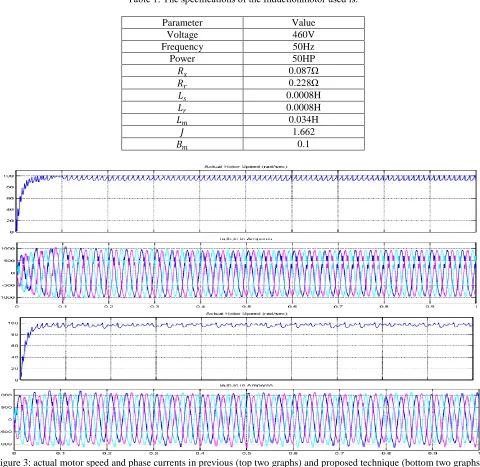
Table 1: The specifications of the Inductionmotor used is:
Parameter Value
Voltage 460V
Frequency 50Hz
Power 50HP
𝑅𝑠 0.087Ω
𝑅𝑟 0.228Ω
𝐿𝑠 0.0008H
𝐿𝑟 0.0008H
𝐿𝑚 0.034H
𝐽 1.662
𝐵𝑚 0.1
ISSN (Print) : 2320 – 3765 ISSN (Online) : 2278 – 8875
I
nternational
J
ournal of
A
dvanced
R
esearch in
E
lectrical,
E
lectronics and
I
nstrumentation
E
ngineering
(An ISO 3297: 2007 Certified Organization)
Vol. 5, Issue 1, January 2016
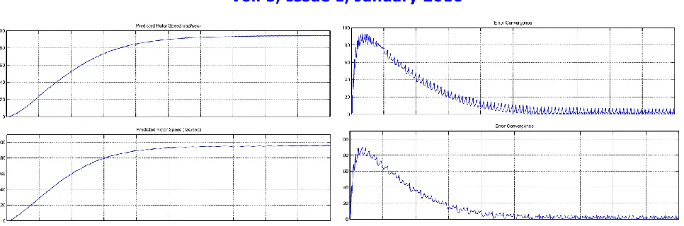
Figure 4: Motor speed estimation and estimation error convergence in previous (top graph) and proposed (bottom graph) technique.
The figure 4 graphs shows that the speed estimation in proposed technique is much better and quick responding. While the error converges much smoothly and quickly in the proposed technique.
VIII. CONCLUSION
An EKF estimator alongside FLC sensorless speed controller of an induction motor has been effectively simulated in Matlab/Simulink environment. The execution truly demonstrates that the controller can be utilized as a part of precise speed controller. The outcomes shows the efficacy of the Extended Kalman filter calculation for estimation purposes. The estimator is steady and fast for every single set speed. The FLC could follow and achieve all the set speeds rapidly. FLC has demonstrated its incredibleness in taking care of indeterminate parameters and unsettling influences. The controller execution has been tried for different step changes in speed in Simulink environment and discovered the same accuracy level in tracking them.
REFERENCES
[1] Bindu V, Unnikrishnan A and Gopika kumari R. “Fuzzy logic based sensorless vector control of Induction motor”, India Conference (INDICON), 2012 Annual IEEE7-9 Dec. 2012.
[2] Young-Real Kim, Seung-Ki Sul, Min-Ho Park “peed Sensorless Vector Control of an Induction Motor Using an Extended Kalman Filter” Industry Applications, IEEE Transactions on (Volume:30 , Issue: 5), Sep/Oct 1994.
[3] J. W. Finch and D. Giaouris, “Controlled ac electrical drives,” IEEE Trans.Ind. Electron., vol. 55, no. 2, pp. 481–491, Feb. 2008.
[4] C. Patel, R. Ramchand, K. Sivakumar, A. Das, and K. Gopakumar, “Arotor flux estimation during zero and active vector periods using currenterror space vector from a hysteresis controller for a sensorless vectorcontrol of IM drive,” IEEE Trans. Ind. Electron., vol. 58, no. 6, pp. 2334–2344, Jun. 2011. [5] T. Orlowska-Kowalska and M. Dybkowski, “Stator-current-based MRASestimator for a wide range speed-sensorless induction-motor drive,” IEEETrans. Ind. Electron., vol. 57, no. 4, pp. 1296–1308, Apr. 2010.
[6] Y. M. Choi and D. G. Gweon, “A high-precision dual-servo stage usingHalbach linear active magnetic bearings,” IEEE/ASME Trans. Mechatronics., vol. 16, no. 5, pp. 925–931, Oct. 2011.
[7] T. Schuhmann, W. Hofmann, and R. Werner, “Improving operational performance of active magnetic bearings using Kalman filter and state feedback control,” IEEE Trans. Ind. Electron., vol. 59, no. 2, pp. 821–829,Feb. 2012.