Implementation of A High-Frequency Link Five
and Eleven level Cascaded Converter with PWM
Controller
Ch. Raghu Viswanath PG Student Scholar Department of Electrical &
Electronics Engineering, Sri Vasavi Engineering College
Tadepallugudem; A.P, India.
U.Chandra Rao Assistant Professor, Department of Electrical &
Electronics Engineering, Sri Vasavi Engineering College
Tadepalligudem; A.P, India.
Dr.Ch.Rambabu Professor, HOD Department of Electrical &
Electronics Engineering, Sri Vasavi Engineering College
Tadepalligudem; A.P, India.
Abstract-Power Electronic converters, especially DC/AC Sinusoidal Pulse Width Modulation inverters have been extending their range of use in industry because of their numerous advantage .Recent advances in solid-state semiconductors have led to the development of medium-voltage power converters which could obviate the need for the step-up transformers of renewable power generation systems. The modular multilevel cascaded converters have been deemed as strong contenders for the development of medium-voltage converters, but the converters require multiple isolated and balanced dc supplies. This paper proposes the high-frequency link multilevel cascaded medium-voltage converter. The common high-frequency link generates multiple isolated and balanced dc supplies for the converter, which inherently minimizes the voltage imbalance and common mode issues. A multilevel phase shifted carrier based sinusoidal PWM switching scheme is utilized to reduce the complexity in control design. Therefore an
identical H-bridge module is used to improve
manufacturability and modularity. When comparing the five and eleven level inverter the voltage levels are increasing the THD value is decreases. The experimental results are analyzed and discussed. It is expected that the proposed new technology will have great potential for future renewable generation systems and smart grid applications.
Index Terms—Direct grid integration, high-frequency link, medium-voltage converters, modular multilevel cascaded (MMC) converters.
I. INTRODUCTION
Power Electronics is the art of convertingelectrical energy from one form to another in anefficient, clean, compact, and robust manner forconvenient utilization. It has found an importantplace in modern technology being core of power andenergy control. It is the technology associated withefficient conversion, control and conditioning ofelectric power from its available input into thedesired output form. Power electronics andconverters utilizing them made a head start when thefirst device the Silicon Controlled Rectifier wasproposed by Bell Labs and commercially producedby General Electric in the earlier fifties.The simplest dc voltage source for a VSI may bea battery bank, which may consist of several cells inseries-parallel combination. Solar photovoltaic cellscan be
another dc voltage source. A voltage source iscalled stiff, if the source voltage magnitude does notdepend on load connected to it. All voltage sourceinverters assume stiff voltage supply at the input .The first topology introduced was the series H-bridge design. This was followed by the diodeclamped converter which utilized a bank of seriescapacitors. A later invention detailed the flying capacitor design in which the capacitors were floating rather than series-connected. Another multileveldesign involves parallel connection of inverter phasesthrough inter-phase reactors. Several combinational designs have also emerged some involving cascadingthe fundamental topologies.
A Three phase five and eleven level Cascaded H-Bridge Inverter Using Low frequency transformer with Single DC Source is presented which overcomes the disadvantage of conventional CMC by employing low frequency transformers with single DC source. Using this proposed model number of DC sources are reduced thus decreasing the complexity and cost of the design. Also a low frequency transformer provides galvanic isolation and is used to obtain the required output voltage level with reduced harmonic components. Relay angles of the converter is obtained based on linearization method and this approach is useful in elimination of lower order harmonics.
II. Proposed Medium-Voltage Converter-Based Direct Grid Integration Systems
http://internationaljournalofresearch.org/ P a g e | 681 Fig. 1. Proposed single-phase five level inverter connected to grid.
For high-power applications, a number of medium/high frequency full-bridge inverters can be used in parallel. The parallel operation of multiple medium/high-frequency inverters enables the proposed technology to use mature low-rated power and low-cost semiconductor devices. To ensure a fixed grid voltage, a constant output voltage of the inverter is maintained.
The inverter output is supplied to the primary windings of a common multi winding medium/high-frequency link. Each secondary winding is connected with the H-bridge inverter through a bridge rectifier. The number of primary windings depends on the number of sources and the number of secondary windings depends on the number of levels of the MMC converter. The grid electrical isolation and voltage imbalance problems are solved inherently through the common medium/high-frequency link. A field-programmable gate array (FPGA)-based control circuit is used to control the magnitude and phase angle, and to ensure the power quality and stability of the system. In this paper, the phase-shifted carrier and third harmonic injected sinusoidal reference-based pulse width modulation (PWM) scheme is used. Desired output voltage level can be generated by cascading more modules on each phase. A high-level converter results in the elimination of the step-up transformer and lower total harmonic distortion (THD) with lower switching frequency. It also leads to the elimination of the output filters and a reduction in running cost. A high-level number attainability also allows for a lower level dc-link voltage requirement for each H-bridge inverter that serves to eliminate the boosters.
B. Design and Analysis of an 11-kV MMC Converter
If ml is the number of levels of the converter, the number
of cascaded modules on each phase can be calculated from
(1) If Vll(rms) is the grid line to line voltage, the minimum
dc-link voltage of each H-bridge inverter cell can be calculated from
(2) To determine the nominal dc-link voltage of each H-bridge inverter cell, a voltage reserve of 4% is assumed, i.e.,
(3) If Ip(rms) is the inverter phase current, the apparent output
power can be calculated from
(4)
The highest voltage rating of the commercially available IGBT is 6.5 kV and this is suitable for 2.54 kV or lower voltage converter systems with the traditional two-level converter topology.
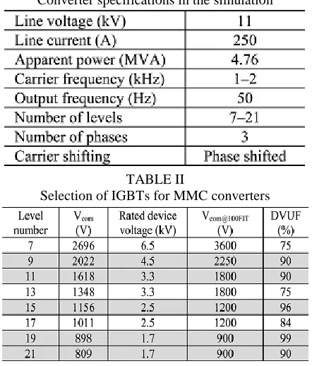
The high-number of levels means that medium-voltage attainability is possible so that the renewable generation system can be connected to the medium-voltage ac network directly. It is also possible to improve the output power quality. The component number and control complexity increase linearly with the increase in the number of levels. Therefore, the optimal selection of the number of converter levels is important in order to achieve the best performance/cost ratio for the system. Table.1 summarizes the converter specifications used for the design and simulation of an 11-kV system.
TABLE I
Converter specifications in the simulation
TABLE II
Selection of IGBTs for MMC converters
Each module dc-link voltage of a seven-level topology-based 11-kV converter is 2696 V which may be supported by the 6.5-kV IGBT. Thus, at least seven-level topology is required to design an 11-kV converter. The output power quality of a 21-level converter is good enough to feed into the 11-kV ac grid directly. The cheap 1.7-kV IGBT can be used to design the 21-level inverter. Therefore, 7-level to 21-level MMC converter topologies are considered for 11-kV systems. The device voltage utilization factor (DVUF), ratio of commutation voltage of respective commutation cells Vcom and device
commutation voltage for a device reliability of 100 failures in time (FIT) due to cosmic radiation (Vcom@100FIT), is summarized in Table II. Higher
to ensure a cost effective design, the converters with level numbers of 9, 11, 15, 19 and 21 for an 11-kV system have been considered for further analysis. The number of arithmetic and logic operations (ALOs) for the switching section and cost of semiconductors are calculated and summarized in Table III. The number of ALOs is used to compare the complexity of the converters. The THD is calculated through the MATLAB/Simulink environment. Fig.8 shows the output voltage waveforms of the converters with level numbers of 5 and 11 their frequency spectrums are shown in Fig.9.
C. Modulation Scheme for MMC Converters
Different types of major reference signals used in the traditional converters can also be employed in the multilevel converter system (e.g., sinusoidal, third harmonic injected sinusoidal, 60◦ modulated sinusoidal and trapezoidal). Each has unique advantages and disadvantages. It is possible to reduce the switching losses by reducing the number of switching occurrences in each period. Flatting the top of the reference signal waveforms (e.g., third harmonic injected sinusoidal, 60◦ modulated sinusoidal and trapezoidal) not only allows the possibility of switching loss reduction but also increases the range of linear modulation. In this paper, four modulation schemes (e.g., the phase-shifted carriers with sinusoidal references (SPWM), the phase-shifted carriers with third harmonic injected sinusoidal references (THPWM), the phase-shifted carriers with 60◦ modulated sinusoidal references (SDPWM), and the phase shifted carriers with trapezoidal type references (TRPWM)) are applied on 7-level to 19-level MMC converter systems to analyze the performance. Of these four modulation schemes, the THPWM scheme gives the best harmonic performance. The SDPWM and TRPWM schemes have higher lower order harmonic contents than that of the SPWM and THPWM schemes. In addition, the SPWM has shown a higher reduction rate for the high level number.
III. DESIGN OF MEDIUM/HIGH FREQUENCYLINK
At the beginning, according to the power converter rating, the transformer-link specifications, such as rated power, frequency, excitation current, and voltage, are calculated. The core material is selected according to the availability, system requirements, and cost. From the specifications of the transformer-link and data sheets of core materials, the transformer-link initial parameters are calculated. These parameters are used as initial values of the optimization process. The volume and weight of the transformer need to be optimized by selecting proper parameters. The winding dimensions depend on the diameter and number of the conductors, and winding structure. Single layer winding provides low ac/dc resistance ratios, but it increases the winding and core dimension significantly. For simplicity of the winding process, a toroidal structure core is considered. Different factors are also considered
during the selection of core dimensions, such as the winding dimensions, toroid hole reserve for natural cooling, maximum temperature limits, maximum power loss, availability of core material stripe dimensions, leakage inductance, and the possibility to induce an equal voltage in multiple secondary windings. Therefore, the design process involves multi physics problems with some critical decision-making tasks.
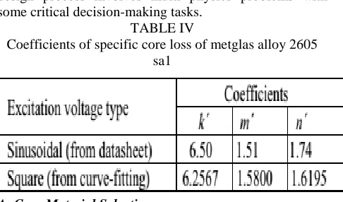
TABLE IV
Coefficients of specific core loss of metglas alloy 2605 sa1
A. Core Material Selection
With the advent of new power semiconductor devices, different soft magnetic materials are conceived with a high magnetic saturation and low power loss to reduce the weight and volume of conventional power transformers. The grain-oriented silicon sheet steels, which are commonly used as the core material for power-frequency transformers, are not suitable for medium/high-frequency applications because of the heavy eddy current loss. The soft ferrites have been widely used in medium- and high-frequency inductors and transformers due to their low price and general availability. Because of the low saturation flux density (only 0.3–0.5 T), which results in the transformer’s large size, they are not suitable for large power applications.
On the other hand, the amorphous alloy and nano crystalline materials have excellent magnetic characteristics for medium/high-frequency applications, such as high permeability, high saturation flux density, and relatively low core losses. The nano crystalline alloy Vitroperm 55Z has a lower specific core loss than that of Vitroperm 500F. Of the other amorphous alloys,
2605SA1 and 2605S3A, the alloy 2714A has the lowest specific core loss but its saturation flux density is only 0.57 T. Although nano crystalline alloy has a lower specific core loss than the amorphous alloys, its saturation flux density (about 1 T) is much lower than that of the amorphous alloys 2605S3A and 2605SA1, which are 1.41 and 1.56 T, respectively. The Metglas alloys 2605SA1 and 2605S3A are iron-based material with specific core losses of about 20 and 7 W/kg, respectively, at 10 kHz sinusoidal excitation of 0.3 T, and these are manufactured by Hitachi Metals, Japan. Taking into account the flux density, specific core loss, cost, and availability, the Metglas alloys 2605S3A and 2605SA1 stripe of 20μm thickness and 25 mm width have been chosen as the core material.
http://internationaljournalofresearch.org/ P a g e | 683
experimental results under sinusoidal voltage excitation, where f is the frequency in kilohertz and B the magnitude of flux density in tesla. For this design, new coefficients are calculated by measurements under square wave voltage excitation.
(5)
B. Calculation of Number of Turns
The medium/high-frequency link works with a square wave voltage; thus, according to Faraday’s law, a triangular flux is required to generate the square wave voltage as shown in Fig.2, where T is the period of excitation voltage, Vmax the maximum excitation voltage,
and ϕmax the maximum flux.
Fig.2. Voltage and flux in a square wave medium/high-frequency link.
The triangular flux can be modeled mathematically as
(6) If N is the number of turns, the expression of the voltage can be deduced by Faraday’s law and (6) as
(7) Where
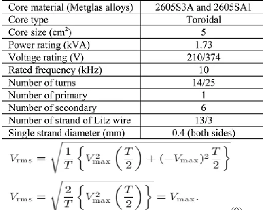
(8) Expression (7) is the mathematical model of the excitation voltage waveform, as shown in Fig.2. The rms value of excitation voltage can be calculated as
TABLE V
Specifications of 1.73KVA high-frequency links
(9) If f is the frequency of the excitation voltage, Bmax is the
maximum flux density, and A is the cross-sectional area of the core, then from (8) and (9) the expression of the number of turns can be deduced as
(10) Table V summarizes the specifications of 1.73 kVA high frequency links.
C. Winding Wire Selection
The skin and proximity effects increase the ac resistances in high-frequency windings. In a conductor, the ac/dc resistance ratios, Kr depends strongly on both the number of layers m and the conductor diameter d. The ac resistance of the mth layer for solid round wires can be represented as follows:
(11) Where
(12)
(13)
(14) and
Fig.3. Detailed power conversion circuit with three-phase five-level converter: for simplicity, single high-frequency inverter is considered.
A VHDL code-based program is used to create the LUT, which contains the sine reference.
IV.MATLAB/SIMULATION RESULTS
Fig.4.Matlab/Simulation model of five level Cascaded H-bridge inverter.
Fig.5. Gate pulses (15 V) of four IGBTs in the top module in phase.
Fig.6 five level inverter voltage.
Fig.7.Three phase voltage.
Fig.8.With Filter and without Filter voltage.
Fig.9.FFT analysis for five level inverter voltage without filter.
Fig.10. Simulated line voltages (after filter circuit) of 1-kV multilevel cascaded converter.
http://internationaljournalofresearch.org/ P a g e | 685 Fig.12. Simulated line currents of the 1-kV multilevel cascaded
converter.
Fig.13.FFT analysis of five level inverter current with filter.
Fig.14.Matlab/Simulation model of eleven level inverter.
Fig.15.three phase voltage for eleven level inverter.
Fig.16.Single phase eleven level inverter voltage for phase a and b.
Fig.17.Three phase voltage and current for inverter.
Fig.18.three phase voltage with filter.
Fig.20.three phase current with filter.
Fig.21.FFT analysis of the voltage with filter.
Fig.22.FFT analysis of the current with filter.
V. CONCLUSION
The multiple secondary windings high-frequencylink can be a good solution to provide multiple isolated and balanced dc supplies for the MMC converter and to ensure electrical isolation between grid and renewable generationsystems. In this paper, the proposed medium-voltage system has been validated by a scaled down three-phase 1-kV system with a five-level and eleven level MMC converter topology. A simulation model for the cascaded multilevel inverter is developed in MATLAB/SIMULINKplatform. The inverter output is a five level phase voltage. The paper presents the main circuit model in simulation results in detail. The FFT analysis results verified the proposed cascaded multilevel inverter with a PWM control method.
REFERENCES
[1] M. R. Islam, Y. G. Guo, and J. G. Zhu, “A transformer-less compact and light wind turbine generating system for offshore wind farms,” in Proc. IEEE Int. Conf. Power Energy, Kota Kinabalu, Malaysia, Dec. 2– 5, 2012, pp. 605–610.
[2] M. R. Islam, Y. G. Guo, and J. G. Zhu, “A medium-frequency transformer with multiple secondary windings for grid connection through H-bridge voltage source converters,” in Proc. Int. Conf. Electr. Mach. Syst., Sapporo, Japan, Oct. 21–24, 2012, pp. 1–6.
[3] H. Akagi, “Classification, terminology, and application of the modular multilevel cascaded converter (MMCC),” IEEE Trans. Power Electron., vol. 26, no. 11, pp. 3119–3130, Nov. 2011.
[4] B. Gultekin and M. Ermis, “Cascaded multilevel converter-based transmission STATCOM: System design methodology and development of a 12 kV ±12 MVAr power stage,” IEEE Trans. Power Electron., vol. 28, no. 11, pp. 4930–4936, Nov. 2013.
[5] F. Z. Peng, J. S. Lai, J. McKeever, and J. VanCoevering, “A multilevel voltage source inverter with separate dc sources for static VAR generation,” IEEE Trans. Ind. Appl., vol. 32, no. 5, pp. 1130– 1138, Sep./Oct. 1996.
[6] M. Hagiwara, K. Nishmura, and H. Akagi, “A medium-voltage motor drive with a modular multilevel PWM inverter,” IEEE Trans. Power Electron., vol. 25, no. 6, pp. 1786–1799, Jul. 2010.
[7] M. Hagiwara and H. Akagi, “Control and experiment of pulse-width modulated modular multilevel converters,” IEEE Trans. Power Electron., vol. 24, no. 7, pp. 1737–1746, Jul. 2009.
[8] M. R. Islam, Y. G. Guo, and J. G. Zhu, “Performance and cost comparison of NPC, FC and SCHB multilevel converter topologies for high-voltage applications,” in Proc. Int. Conf. Electr. Mach. Syst., Beijing, China, Aug. 20–23, 2011, pp. 1–6.
[9] F. Deng and Z. Chen, “A control method for voltage balancing in modular multilevel converters,” IEEE Trans. Power Electron., vol. 29, no. 1, pp. 66– 76, Jan. 2014.
[10] T. Zhao, G. Wang, S. Bhattachaya, and Q. Huang, “Voltage and power balance control for a cascaded H-bridge converter-based solid-state transformer,” IEEE Trans. Power Electron., vol. 28, no. 4, pp. 1523–1532, Apr.2013.
[11] X. She, A. Q. Huang, T. Zhao, and G. Wang, “Coupling effect reduction of a voltage-balancing controller in single-phase cascaded multilevel converters,” IEEE Trans. Power Electron., vol. 27, no. 8, pp. 3530–3543, Aug. 2012.
[12] C. H. Ng, M. A. Parker, L. Ran, P. J. Tavner, J. R. Bumby, and E. Spooner, “A multilevel modular converter for a large, light weight wind turbine generator,” IEEE Trans. Power Electron., vol. 23, no. 3, pp. 1062–1074, May 2008.
[13] X. Yuan, Y. Li, J. Chai, and M. Ma, “A modular direct-drive permanent magnet wind generator system eliminating the grid-side transformer,” in Proc. 13th Eur. Conf. Power Electron. Appl., Barcelona, Sep. 2009, pp. 1– 7.